- Главная
- Разное
- Дизайн
- Бизнес и предпринимательство
- Аналитика
- Образование
- Развлечения
- Красота и здоровье
- Финансы
- Государство
- Путешествия
- Спорт
- Недвижимость
- Армия
- Графика
- Культурология
- Еда и кулинария
- Лингвистика
- Английский язык
- Астрономия
- Алгебра
- Биология
- География
- Детские презентации
- Информатика
- История
- Литература
- Маркетинг
- Математика
- Медицина
- Менеджмент
- Музыка
- МХК
- Немецкий язык
- ОБЖ
- Обществознание
- Окружающий мир
- Педагогика
- Русский язык
- Технология
- Физика
- Философия
- Химия
- Шаблоны, картинки для презентаций
- Экология
- Экономика
- Юриспруденция
New S350CE+ STT Module_Sept2014 презентация
Содержание
- 1. New S350CE+ STT Module_Sept2014
- 4. S350CE On/Off Switch 4 pin Work Sense
- 5. S350CE G6682 Control Board CE Filter
- 6. S350CE Not Used Circuit Breaker Sync Tandem
- 7. S350CE 3 phase only Replace line cord when operating over 450 VAC
- 8. S350CE Input Choke Output Choke Input Control Board Power Conversion Assembly
- 13. S350CE Feeder:
- 14. S350CE Software Location Control Board Hardware
- 15. POWER CONVERSION ASSEMPLY
- 17. POWER CONVERSION ASSEMBLY
- 18. Power Wave S350 Power-Up Sequence Once voltage
- 19. Power Wave S350 Power-Up Sequence After the
- 20. S350CE 3 phase only Replace line cord
- 21. Analog and Digital circuits control the current
- 23. Buck/Boost Theory of Operation Depending upon the
- 24. Thermostat Signal to Control Board
- 25. Pause between sounds/flashes indicating a specific digit:
- 26. PFC Control Board (G5915 series) Auxiliary Power
- 27. PFC CONTROL BOARD Use DVM Diode check
- 28. First Stage Function Detects thermal trips that
- 29. Primary Thermal Protection Location: SMT Part,
- 30. Relay and DC Link Capacitor 3-phase input
- 31. Power Conversion Assembly First Stage – Buck Boost
- 32. Second Stage Functions Converts rectified 400 Volts
- 33. Planar Transformer Design
- 34. Functions Multi-Phase Chopper Used to control welding
- 36. Implementation Multi-Phase Chopper + 48 Volt
- 37. Functions Control PC Board Serves as the
- 38. Data Input to IGBTs & Supply
- 39. Secondary Thermostat Status LED On
- 40. Thermal Protection Function Secondary Thermal Circuit
- 41. Simplified Test Procedure Current Transducer (S18504-6)
- 42. “Must Have” LED’s
- 43. ERROE CODES POWER WAVE S350
- 44. STT Module Service Training K2921-1
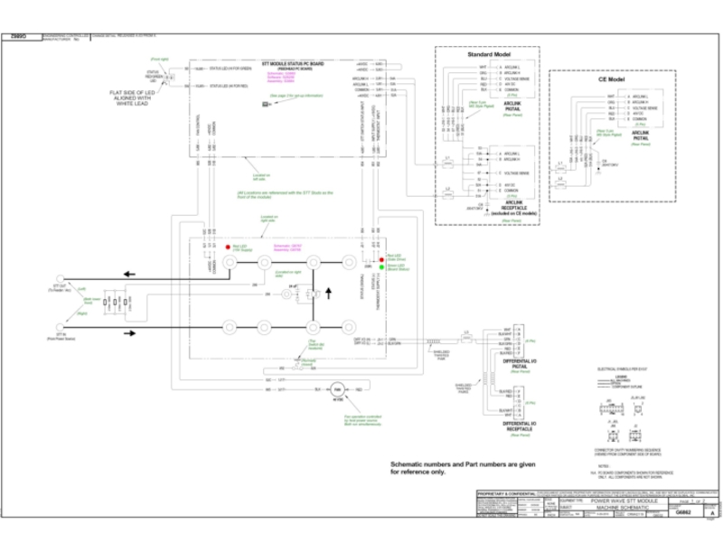
- 47. STT Module
- 48. STT Module Typical Mounting
- 49. STT Module Connection Diagram (CE) (Reference M22498)
- 50. STT Module STT Update Kit (CE) Included with K2921-1 for S350 CE
- 51. STT - The Basics STT Module Typical
- 52. STT Module Component Location
- 53. Functions STT Status PC Board (S28250/G3884 series)
- 54. 40VDC IN
- 55. STT Status PC Board (S28250/G3884 series)
- 56. Troubleshooting with External LED STT Status
- 57. STT Status PC Board (S28250/G3884 series) Troubleshooting
- 58. Troubleshooting Input and Output Circuits STT
- 59. Functions STT Switch PC Board (G6768 series)
- 60. 40VDC Input LED 3
- 61. STT Switch PC Board (G6768 series)
- 62. STT Switch PC Board (G6768 series) Functional Block Diagram
- 63. STT Switch PC Board (G6768 series) Gate
- 64. STT Switch PC Board (G6768 series) Snubber
- 65. STT Switch PC Board (G6768 series) Troubleshooting


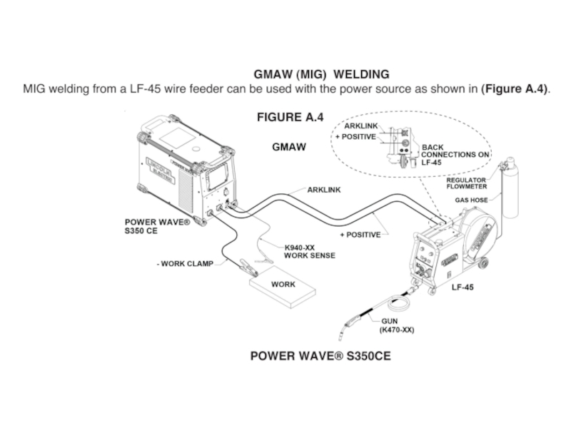
Слайд 4S350CE
On/Off Switch
4 pin Work Sense
Fault LED
Thermal LED
No optional UI kit
“+”
TwistMate (Dinse)
“-”
TwistMate
5 pin ArcLink Connector
“-”TwistMate (Dinse)5 pin ArcLink Connector")

Слайд 6S350CE
Not Used
Circuit
Breaker
Sync Tandem
STT Connector, part of STT module
EtherNET
Line Cord
Optional
DeviceNET
Water cooler
Connection access
Easy access fans
Future Development


Слайд 14S350CE
Software Location
Control Board
Hardware
Operates with K2921-1 STT Module
Use PF-25M’s, PF-10M’s LF-45


Слайд 18Power Wave S350
Power-Up Sequence
Once voltage is applied to the machine via
This power supply is responsible for regulating the +/- 15 volts for the control circuits, as well as the +15 volts for the buck & boost IGBTs.
LED 2 on PFC Control Board indicates a proper functioning power supply.
Once the auxiliary power supply is functioning, the PFC control and full bridge circuits will turn on, close a relay, and provide a soft-start function for the buck-boost power section and simultaneously for the full bridge inverter located on the Power Conversion Assembly.
The PFC Control Board soft-start function begins with a low duty cycle and gradually increases the duty cycle until the buck-boost has met its pre-charge requirements. Completion time is dependant on the input voltage to the machine.

Слайд 19Power Wave S350
Power-Up Sequence
After the soft-start sequence is complete, the primary
The Planar transformer has two auxiliary windings, the first one is used to provide a 48 Volt power supply for the fans & the DC Bus Board. The DC Bus Board then provides 40VDC to the Control Board & Arclink Receptacle (S3 5Pin).
The 48 Volt secondary follows the same pre-charge sequence as the 100 Volt secondary.
Fan defaults to low speed unless a weld is made.
The machine is now idle and ready to make a weld

Слайд 20S350CE
3 phase only
Replace line cord when operating over 450 VAC
If S350CE

Слайд 21Analog and Digital circuits control the current shaping, regulated bus voltage,
Activated via open-collector signal from PFC PCB
First Stage Function On the Power Conversion Assembly & PFC PCB
Under Fault Conditions the relay will generally close 50 ms after power is applied to the machine and immediately reopen.
Buck switch operates at 325 Vac or more, boost switch is held off for the most part (LED 3 may be off at idle, LED 11 is ON)
Relay Provides Softstart function for DC Link Capacitor
Limits inrush current during DC Link capacitor charging
PFC Control Board
Powered from the AC line via a diode on the Power Conversion Assembly and an auxiliary power supply on the PFC Control Board
Auxiliary power supply requires 180 – 900 Vdc, LED 2 must be on during proper operation
Relay Operation
Under normal operating conditions, the relay should close 50 ms after power is applied to the machine
Shorts 100 Ohm resistor after pre-charge
Power Conversion Assembly Converts rectified 60Hz input to a regulated 400 Volts dc
Topology consists of a buck converter followed by a boost converter
Boost switch operates at 230 Vac or less, buck switch is held on (LED 3 is On and LED 11 is On)

Слайд 22
SHUNT
The Shunt sends a feed back signal
to the PFC Bd to
Power Factor up to 97%
Input voltage filter choke / capacitor
DC
LED2
POWER
CONVERSION
ASSEMPLY
POWERCONVERSION ASSEMBLY

Слайд 23Buck/Boost Theory of Operation
Depending upon the input line voltage, the PFC


Слайд 25Pause between sounds/flashes indicating a specific digit: 0.5 seconds
Buzzer Error Codes
PFC
First and Second Stage Error Codes are sounded on buzzer and LED 1 on Input Control Board
RED LED 1 can be seen through the side louvers of the machine
Pause before repeating the code: 3.5 seconds
Pause between digits of the code: 1.5 seconds
First")
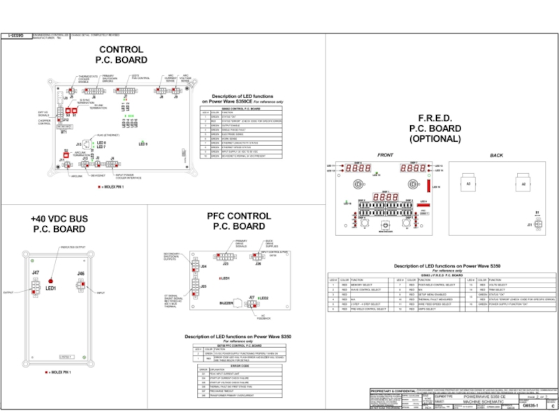
Слайд 26PFC Control Board (G5915 series)
Auxiliary Power Supply and PFC Circuits
HIGH VOLTAGE
J26
J24
J23
J25
BUZZER
AUXILIARY POWER LED 2
ERROR CODE LED 1
J27
* LEDs can be seen through side louvers
Auxiliary Power Supply and PFC CircuitsHIGH VOLTAGE AUXILIARY POWER SUPPY J26")
Слайд 27PFC CONTROL BOARD
Use DVM Diode check function from 8J42 to 1J42
Auxiliary
Machine will not power up
LED 2 will be off or blinking if there is a problem with the PFC Control Board
Can be seen through side louvers of the machine
Failure of this circuit will fail the auxiliary input diode
POWER CONVERSION ASSEMBLY Auxiliary Input Diode Failure
Failure of this component is a result of a auxiliary power supply failure
Forward Voltage should be greater than 0.3 Volts

Слайд 28First Stage Function
Detects thermal trips that may occur on the first
Signals from PFC Control Board to Power Conversion Assembly
Connector J23 & J26 on PFC Control Board
Main & Auxiliary Boost Gate Drives
Main & Auxiliary Buck Gate Drives
+15 Volt dc Power Supplies for the Main and Auxiliary Buck Drives
Main Relay Drive
Full Bridge Gate Drives
Connector J27 on PFC Control Board
Filter AC Input Power Supply for the Input Control Board
Signals from Power Conversion Assembly to PFC Control Board
Connector J25 on PFC
Buck-Boost Current Feedback
Rectified AC Input Voltage
Regulated 400 Volt Bus Feedback
Thermostat Pull-Down Signal
Full Bridge CT Feedback
Input and Output Signals

Слайд 29Primary Thermal Protection
Location:
SMT Part, First and Second Stage Module (M21214-10)
Function
Primary
Protects machine against reduced airflow or overload.
Fan OFF / Output disabled
All stages cease operation and machine appears to be off – Buzzer will continue to sound
All Thermostats are normally closed
Mechanical thermostats DO NOT immediately reset!
First stage module thermostat opens at 90°C, resets at 60°C
Thermostat Test
Primary Circuit
G4770 board (6J42 to B49) – should measure short
FunctionPrimary Thermal Circuit Protects machine")
Слайд 30Relay and DC Link Capacitor
3-phase input rectifier converts AC line voltage
Perform diode tests between line input (B30, B31, B32) and rectifier outputs (B10, B13)
100 ohm resistor provides precharge path for DC Link Capacitor. Relay closes after precharge is complete.
Measure resistance from B12 to B10 with machine turned off.
100 ohms expected
OPEN indicates resistor failure
SHORT indicates fused relay contacts
B30
B10
B31
B12
DC LINK CAPACITOR
RELAY
B32
B13


Слайд 32Second Stage Functions
Converts rectified 400 Volts dc input to an unregulated
Topology consists of a full bridge inverter followed by a center tap rectifier
Full bridge switches at 60 Khz with a 150 ns dead time
Open-loop control is used and the 100 Volts dc output is unregulated
Interacts directly with Input Control Board
Power Board provides primary side current feedback for inverter protection
The machine is now idle and ready to make a weld
The Planar transformer has two auxiliary windings.
The first one is used to provide a 48 Volt power supply for the fans & the DC Bus Board. Green LED1 on if 48VDC power supply if present on Power Board.
The DC Bus Board then provides 40VDC to the Control Board & Arclink Receptacle (S3 5Pin).

Слайд 33
Planar Transformer
Design Features
Printed circuit board
Individually sealed
Small footprint allows
for mounting directly onto
Incorporated auxiliary winding

Слайд 34Functions
Multi-Phase Chopper
Used to control welding Voltage and Current
100 Volt DC input
Six chopper phases in parallel that turn on 60 degrees out of phase
Two phases each conduct 180 degrees out of phase through the same output choke
Power Board receives commands from the Control board. Power Board uses this command and determines the on-time of the six chopper IGBTs.

Слайд 35
SHUNT
48VDC
48VDC HIGH
24VDC LOW
100VDC
48VDC
FAN ALWAYS ON
LOW OR HIGH
322 to 324=400
TO BUS
P.C.BOARD
LED
40VDC
To S1
For Feeder
40VDC
To Control
Board
POWER
CONVERSION
ASSEMPLY
POWERCONVERSION ASSEMBLY

Слайд 36
Implementation
Multi-Phase Chopper
+ 48 Volt dc auxiliary power supply indicator LED1
Six LEDs
Intensity of each LEDS 5-10 is related to the on-time of each of the IGBTs
+15 Volt dc power supply for secondary control circuits LED4

Слайд 37Functions
Control PC Board
Serves as the main communication interface
ArcLink master
Ethernet
Controls the Chopper
Transmits welding commands via differential signaling
Controls welding output based on ...
User settings
Voltage and Current feedback
Welding software

Слайд 38
Data Input to IGBTs
& Supply Voltage
40VDC From
Bus BD
Low & High
Speed Fan
Control
Power Board
Voltage
Sense
Leads
ArcLink
To and
From
Receptacle S3
PF10M
216
216

Слайд 39Secondary
Thermostat
Status LED
On Front
Thermostat LED
On Front
This is where
The STT
Differential I/O
Connects
S350
G6682 Control Board
- Depopulated version of G4800

Слайд 40Thermal Protection
Function
Secondary Thermal Circuit
Protects machine against reduced airflow or overload.
Fan ON / Output disabled
Thermal fault logged and indicated by Thermal Error and Thermal LED on User Interface board (Error 36)
Locations:
Secondary Heatsink
All Thermostats are normally closed
Mechanical thermostats DO NOT immediately reset!
Secondary heatsink thermostat opens at 68°C, resets at 48°C
Secondary Circuit
Digital Control board (2J5 to 3J5) – should measure short

Слайд 41Simplified Test Procedure
Current Transducer (S18504-6)
Verify 30 VDC present at supply leads
Check
Calibration tab in the “Lincoln Diagnostic Utility”
Verify Transducer Vfb verses actual Output Current per chart
Verify 30 VDC present at supply leadsCheck the feedback with a")
Слайд 42“Must Have” LED’s
10 DeviceNet Power
Status LED’s
Control PC Board
DIP Switches – Factory Default
All ON
S3
S1
S2
9 Power Supply
1 Board Status
Ethernet Connectivity
7 Ethernet Status
Flashing indicates data
DeviceNet Connectivity
10


 (Reference M22498)")
 Included with K2921-1 for S350 CE")


Слайд 53Functions
STT Status PC Board (S28250/G3884 series)
Identifies STT Module to ArcLink Network
Receives
Communicates Errors to Power Source via ArcLink
Drives Fan
Fan driven via Power Source Control Board command
Controls external Status LED
Identifies STT Module to ArcLink NetworkReceives Switch PCB Status and")
Слайд 5440VDC IN
40VDC out
To STT
Switch Board
Arclink
Thermostat
851-852
Closed < 1VDC
Open >10VDC
Arclink
40VDC IN

")
Слайд 56Troubleshooting with External LED
STT Status PC Board (S28250/G3884 series)
No LED
Check LED placement and connections
Verify 40 Vdc input (J81-4 to J81-3)
Fast blinking Green LED – Mapping Error
Verify continuity of ArcLink cable (pins “A” and “B”)
Verify ArcLink Pigtail to Status PCB
Pin “A” to J81-1
Pin “B” to J81-2
Red and Green Blinking LED
Read and interpret Error Code
Power Wave Manager Diagnostic Tab
No LED Check LED placement and")
Слайд 57STT Status PC Board (S28250/G3884 series)
Troubleshooting with External LED
Error codes for
(Indicated on the externally mounted Status LED)
Troubleshooting with External LEDError codes for the Power Wave STT")
Слайд 58Troubleshooting Input and Output Circuits
STT Status PC Board (S28250/G3884 series)
Thermostat
Best Measured across the Thermostat
Closed < 1VDC
Open > 10VDC
Switch PCB Status Input
Best Measured at STT Switch PC Board (J2-5 to J2-1)
Closed < 1VDC
Open > 10VDC
Fan Output
Open Collector style (J88-5)
Supplied from STT Switch PCB (J1-6)
Thermostat InputBest Measured across the")
Слайд 59Functions
STT Switch PC Board (G6768 series)
Interrupts Power Source Output Current
Includes integral
Resistor bank located off Board
Includes on board Protection Circuitry
Intelligent Gate Drive
Minimum ON time = 223µsec
Maximum OFF time 1.5 seconds
Under Voltage Lockout (ERROR 99)
Over Voltage Protection
Turns Switch ON if Snubber voltage exceeds 500V
Reverse Polarity Protection (ERROR 99)
Only when connected through Status PCB (ArcLink)
Interrupts Power Source Output CurrentIncludes integral snubber diodes and capacitorsResistor")
Слайд 6040VDC
Input
LED 3
15VDC
In
To STT
Module
Switch
Status
input
Thermostat
851-852
Closed < 1VDC
Open >10VDC
Dif
40VDC
Input
When welding
885 goes to COM
And Fan turns on
If resistor is
disconnected
Leads 288 & 299
could cause Error 99
With output on

")
Functional Block Diagram")
Слайд 63STT Switch PC Board (G6768 series)
Gate Drive Signal (RS-485 Differential signal
Gate Drive Signal (RS-485 Differential signal from Power Source)")
Слайд 64STT Switch PC Board (G6768 series)
Snubber Configuration
Capacitor
Absorbs initial energy
Resistor
Limits maximum
Provides path to sustain arc current
Dissipates Energy from weld circuit inductance
Snubber ConfigurationCapacitorAbsorbs initial energyResistor Limits maximum voltageProvides path to sustain")
Слайд 65STT Switch PC Board (G6768 series)
Troubleshooting
On Board LED’s for the STT
(Visible through the rear and left side louvers)
TroubleshootingOn Board LED’s for the STT Switch PC Board(Visible through")