- Главная
- Разное
- Дизайн
- Бизнес и предпринимательство
- Аналитика
- Образование
- Развлечения
- Красота и здоровье
- Финансы
- Государство
- Путешествия
- Спорт
- Недвижимость
- Армия
- Графика
- Культурология
- Еда и кулинария
- Лингвистика
- Английский язык
- Астрономия
- Алгебра
- Биология
- География
- Детские презентации
- Информатика
- История
- Литература
- Маркетинг
- Математика
- Медицина
- Менеджмент
- Музыка
- МХК
- Немецкий язык
- ОБЖ
- Обществознание
- Окружающий мир
- Педагогика
- Русский язык
- Технология
- Физика
- Философия
- Химия
- Шаблоны, картинки для презентаций
- Экология
- Экономика
- Юриспруденция
3D Viewing Pipeline презентация
Содержание
- 1. 3D Viewing Pipeline
- 2. * Computer Graphics Normalized view space Modeling
- 3. Contents Introduction Clipping Volume Clipping Strategies Clipping Algorithm
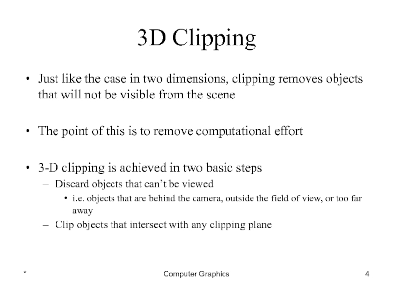
- 4. * Computer Graphics 3D Clipping Just like
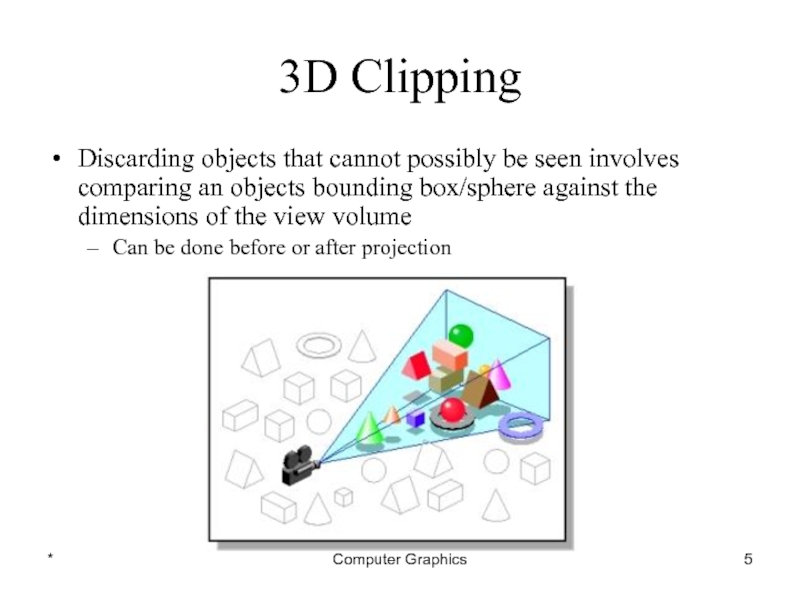
- 5. * Computer Graphics 3D Clipping Discarding objects
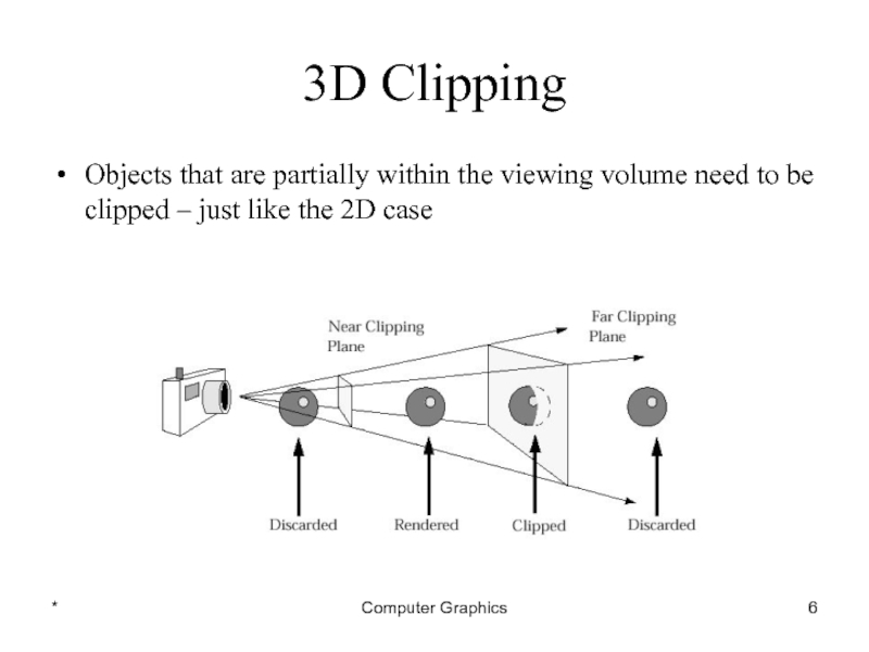
- 6. * Computer Graphics 3D Clipping Objects that
- 7. Contents Introduction Clipping Volume Clipping Strategies Clipping Algorithm
- 8. * Computer Graphics The Clipping Volume In
- 9. * Computer Graphics The Clipping Volume In
- 10. * Computer Graphics The Clipping Volume After
- 11. Contents Introduction Clipping Volume Clipping Strategies Clipping Algorithm
- 12. * Computer Graphics Clipping Strategies Because of
- 13. * Computer Graphics Clipping Strategies The canonical
- 14. * Computer Graphics Clipping Strategies The canonical
- 15. * Computer Graphics Clipping Strategies We perform
- 16. * Computer Graphics Clipping Strategies The basis
- 17. Contents Introduction Clipping Volume Clipping Strategies Clipping Algorithm
- 18. * Computer Graphics Clipping Algorithms 3D clipping
- 19. * Computer Graphics 3D Cohen-Sutherland Line Clipping
- 20. * Computer Graphics 3D Cohen-Sutherland Line Clipping
- 21. * Computer Graphics 3D Cohen-Sutherland Line Clipping
- 22. * Computer Graphics 3D Cohen-Sutherland Line Clipping
- 23. * Computer Graphics 3D Cohen-Sutherland Line Clipping
- 24. * Computer Graphics 3D Cohen-Sutherland Line Clipping
- 25. * Computer Graphics 3D Cohen-Sutherland Line Clipping
- 26. * Computer Graphics 3D Cohen-Sutherland Line Clipping
- 27. * Computer Graphics 3D Cohen-Sutherland Line Clipping
- 28. * Computer Graphics 3D Cohen-Sutherland Line Clipping
- 29. Any Question !
Слайд 2*
Computer Graphics
Normalized view space
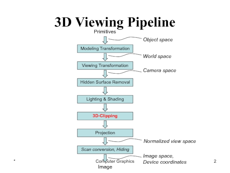
Modeling Transformation
Viewing Transformation
Lighting & Shading
3D-Clipping
Projection
Scan conversion, Hiding
Primitives
Image
Object space
World
space
Camera space
Image space,
Device coordinates
Hidden Surface Removal
3D Viewing Pipeline
Слайд 4*
Computer Graphics
3D Clipping
Just like the case in two dimensions, clipping removes
objects that will not be visible from the scene
The point of this is to remove computational effort
3-D clipping is achieved in two basic steps
Discard objects that can’t be viewed
i.e. objects that are behind the camera, outside the field of view, or too far away
Clip objects that intersect with any clipping plane
The point of this is to remove computational effort
3-D clipping is achieved in two basic steps
Discard objects that can’t be viewed
i.e. objects that are behind the camera, outside the field of view, or too far away
Clip objects that intersect with any clipping plane
Слайд 5*
Computer Graphics
3D Clipping
Discarding objects that cannot possibly be seen involves comparing
an objects bounding box/sphere against the dimensions of the view volume
Can be done before or after projection
Can be done before or after projection
Слайд 6*
Computer Graphics
3D Clipping
Objects that are partially within the viewing volume need
to be clipped – just like the 2D case
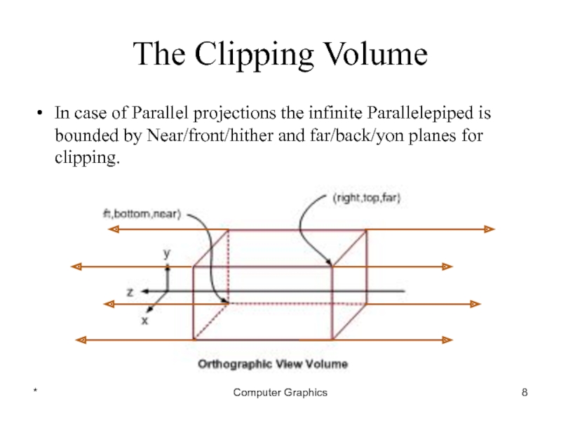
Слайд 8*
Computer Graphics
The Clipping Volume
In case of Parallel projections the infinite Parallelepiped
is bounded by Near/front/hither and far/back/yon planes for clipping.
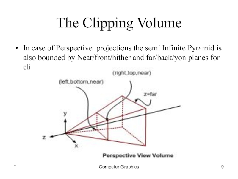
Слайд 9*
Computer Graphics
The Clipping Volume
In case of Perspective projections the semi Infinite
Pyramid is also bounded by Near/front/hither and far/back/yon planes for clipping
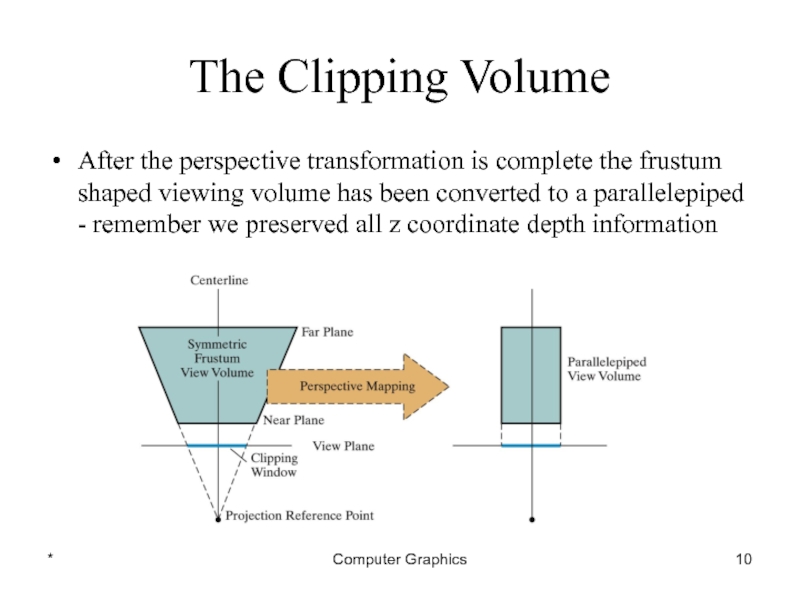
Слайд 10*
Computer Graphics
The Clipping Volume
After the perspective transformation is complete the frustum
shaped viewing volume has been converted to a parallelepiped - remember we preserved all z coordinate depth information
Слайд 12*
Computer Graphics
Clipping Strategies
Because of the extraordinary computational effort required, two types
of clipping strategies are followed:
Direct Clipping: The clipping is done directly against the view volume.
Canonical Clipping: Normalization transformations are applied which transform the original view volume into normalized (canonical) view volume. Clipping is then performed against canonical view volume.
Direct Clipping: The clipping is done directly against the view volume.
Canonical Clipping: Normalization transformations are applied which transform the original view volume into normalized (canonical) view volume. Clipping is then performed against canonical view volume.
Слайд 13*
Computer Graphics
Clipping Strategies
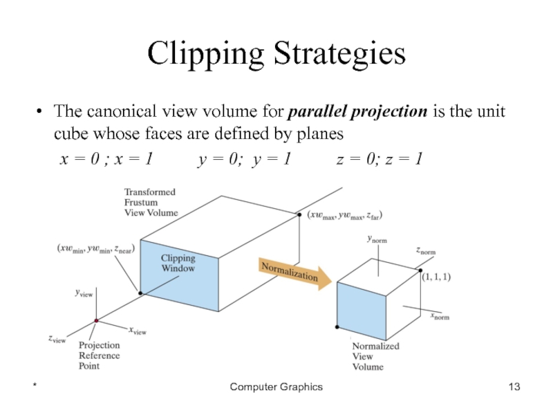
The canonical view volume for parallel projection is the
unit cube whose faces are defined by planes
x = 0 ; x = 1 y = 0; y = 1 z = 0; z = 1
x = 0 ; x = 1 y = 0; y = 1 z = 0; z = 1
Слайд 14*
Computer Graphics
Clipping Strategies
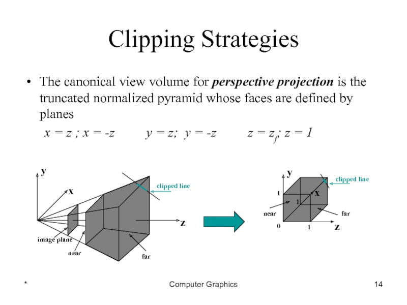
The canonical view volume for perspective projection is the
truncated normalized pyramid whose faces are defined by planes
x = z ; x = -z y = z; y = -z z = zf; z = 1
x = z ; x = -z y = z; y = -z z = zf; z = 1
Слайд 15*
Computer Graphics
Clipping Strategies
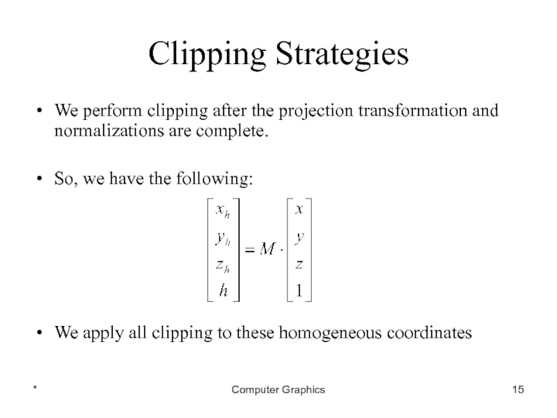
We perform clipping after the projection transformation and normalizations
are complete.
So, we have the following:
We apply all clipping to these homogeneous coordinates
So, we have the following:
We apply all clipping to these homogeneous coordinates
Слайд 16*
Computer Graphics
Clipping Strategies
The basis of canonical clipping is the fact that
intersection of line segments with the faces of canonical view volume require minimal calculations.
For perspective views, additional clipping may be required to avoid perspective anomalies produced by the projecting objects that are behind view point.
For perspective views, additional clipping may be required to avoid perspective anomalies produced by the projecting objects that are behind view point.
Слайд 18*
Computer Graphics
Clipping Algorithms
3D clipping algorithms are direct adaptation of 2D clipping
algorithms with following modifications:
For Cohen Sutherland: Assignment of out codes
For Liang-Barsky: Introduction of new equations
For Sutherland Hodgeman: Inside/Out side Test
In general: Finding the intersection of Line with plane.
For Cohen Sutherland: Assignment of out codes
For Liang-Barsky: Introduction of new equations
For Sutherland Hodgeman: Inside/Out side Test
In general: Finding the intersection of Line with plane.
Слайд 19*
Computer Graphics
3D Cohen-Sutherland Line Clipping
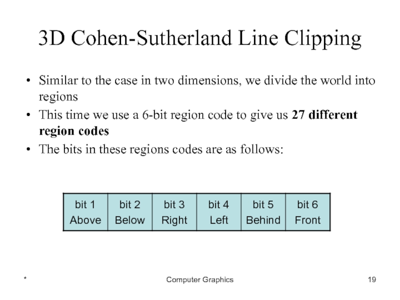
Similar to the case in two dimensions,
we divide the world into regions
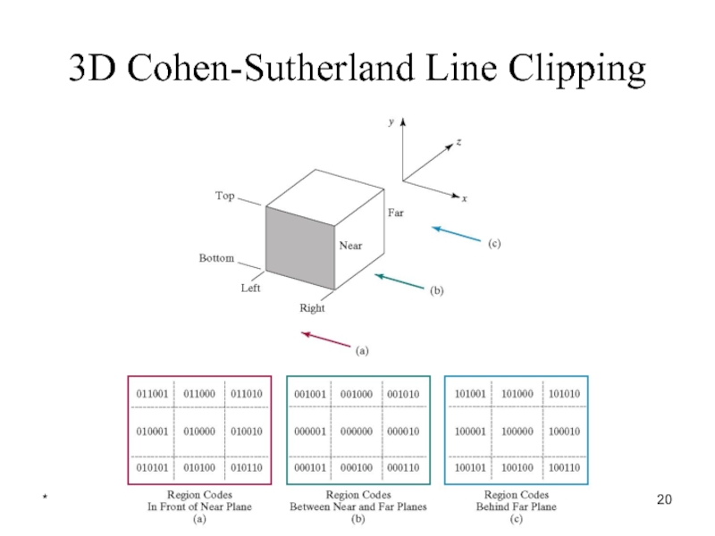
This time we use a 6-bit region code to give us 27 different region codes
The bits in these regions codes are as follows:
This time we use a 6-bit region code to give us 27 different region codes
The bits in these regions codes are as follows:
Слайд 21*
Computer Graphics
3D Cohen-Sutherland Line Clipping
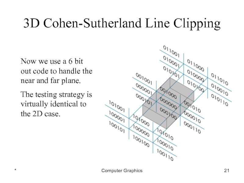
Now we use a 6 bit out
code to handle the near and far plane.
The testing strategy is virtually identical to the 2D case.
The testing strategy is virtually identical to the 2D case.
Слайд 22*
Computer Graphics
3D Cohen-Sutherland Line Clipping
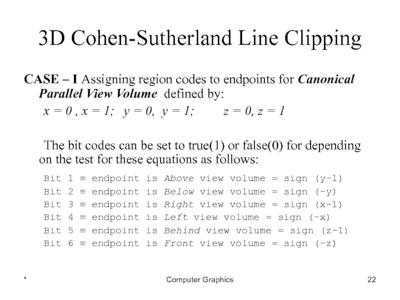
CASE – I Assigning region codes to
endpoints for Canonical Parallel View Volume defined by:
x = 0 , x = 1; y = 0, y = 1; z = 0, z = 1
The bit codes can be set to true(1) or false(0) for depending on the test for these equations as follows:
Bit 1 ≡ endpoint is Above view volume = sign (y-1)
Bit 2 ≡ endpoint is Below view volume = sign (-y)
Bit 3 ≡ endpoint is Right view volume = sign (x-1)
Bit 4 ≡ endpoint is Left view volume = sign (-x)
Bit 5 ≡ endpoint is Behind view volume = sign (z-1)
Bit 6 ≡ endpoint is Front view volume = sign (-z)
Слайд 23*
Computer Graphics
3D Cohen-Sutherland Line Clipping
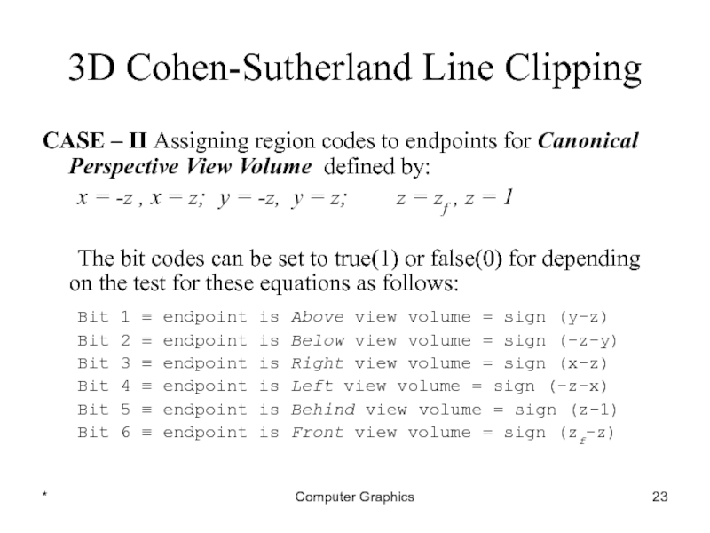
CASE – II Assigning region codes to
endpoints for Canonical Perspective View Volume defined by:
x = -z , x = z; y = -z, y = z; z = zf , z = 1
The bit codes can be set to true(1) or false(0) for depending on the test for these equations as follows:
Bit 1 ≡ endpoint is Above view volume = sign (y-z)
Bit 2 ≡ endpoint is Below view volume = sign (-z-y)
Bit 3 ≡ endpoint is Right view volume = sign (x-z)
Bit 4 ≡ endpoint is Left view volume = sign (-z-x)
Bit 5 ≡ endpoint is Behind view volume = sign (z-1)
Bit 6 ≡ endpoint is Front view volume = sign (zf-z)
Слайд 24*
Computer Graphics
3D Cohen-Sutherland Line Clipping
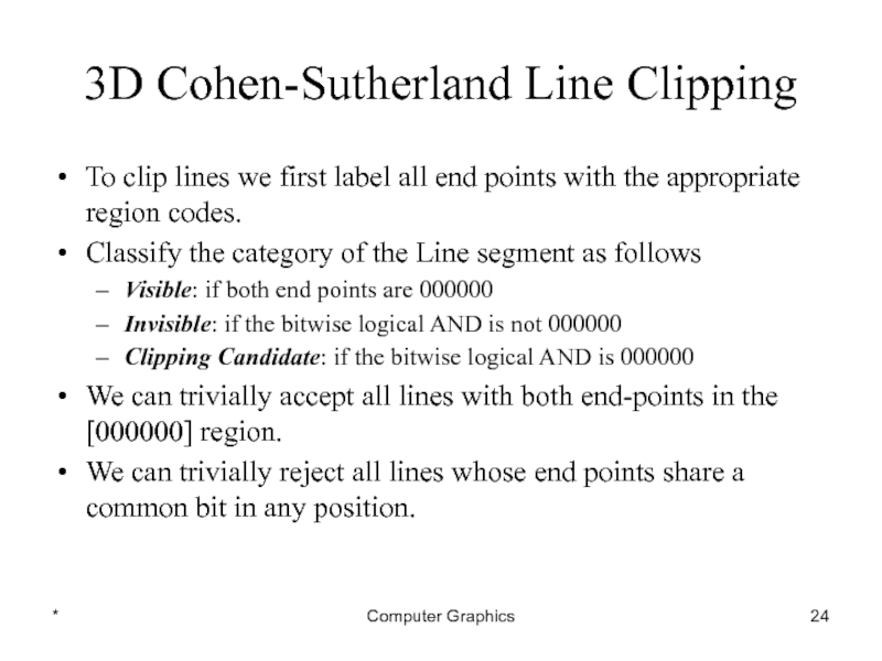
To clip lines we first label all
end points with the appropriate region codes.
Classify the category of the Line segment as follows
Visible: if both end points are 000000
Invisible: if the bitwise logical AND is not 000000
Clipping Candidate: if the bitwise logical AND is 000000
We can trivially accept all lines with both end-points in the [000000] region.
We can trivially reject all lines whose end points share a common bit in any position.
Слайд 26*
Computer Graphics
3D Cohen-Sutherland Line Clipping
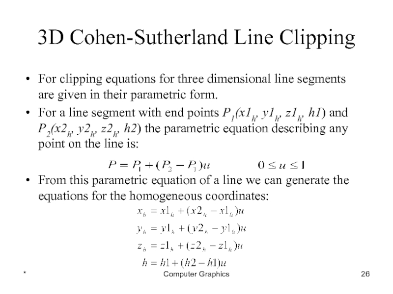
For clipping equations for three dimensional line
segments are given in their parametric form.
For a line segment with end points P1(x1h, y1h, z1h, h1) and P2(x2h, y2h, z2h, h2) the parametric equation describing any point on the line is:
From this parametric equation of a line we can generate the equations for the homogeneous coordinates:
For a line segment with end points P1(x1h, y1h, z1h, h1) and P2(x2h, y2h, z2h, h2) the parametric equation describing any point on the line is:
From this parametric equation of a line we can generate the equations for the homogeneous coordinates:
Слайд 27*
Computer Graphics
3D Cohen-Sutherland Line Clipping
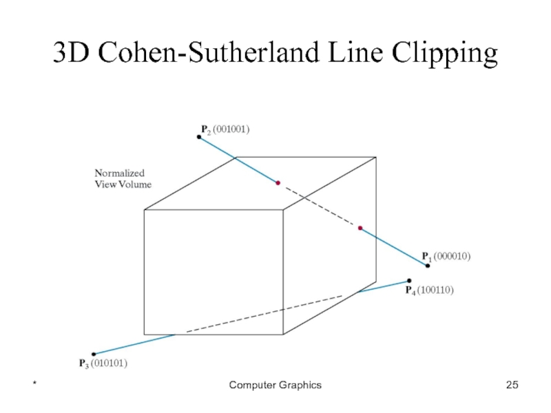
Consider the line P1[000010] to P2[001001]
Because the
lines have different values in bit 2 we know the line crosses the right boundary
Слайд 28*
Computer Graphics
3D Cohen-Sutherland Line Clipping
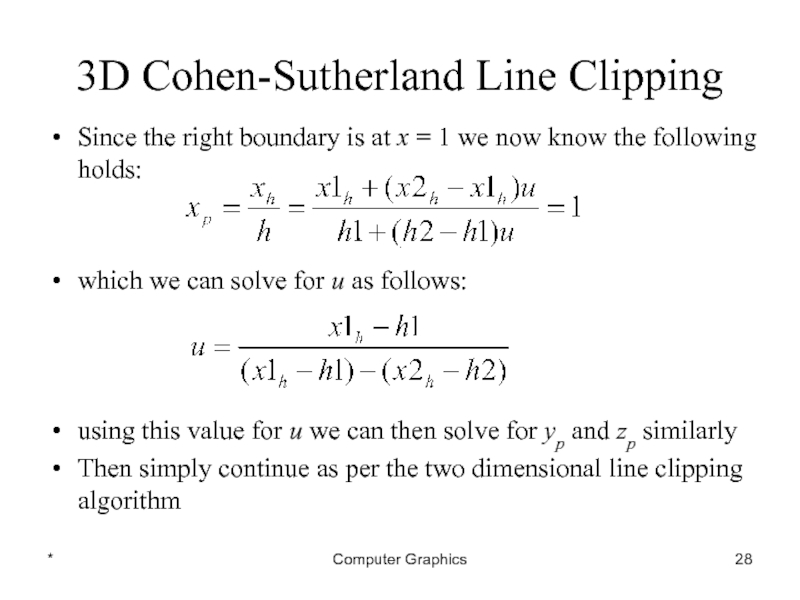
Since the right boundary is at x
= 1 we now know the following holds:
which we can solve for u as follows:
using this value for u we can then solve for yp and zp similarly
Then simply continue as per the two dimensional line clipping algorithm
which we can solve for u as follows:
using this value for u we can then solve for yp and zp similarly
Then simply continue as per the two dimensional line clipping algorithm
![*Computer Graphics3D Cohen-Sutherland Line ClippingConsider the line P1[000010] to P2[001001]Because the lines have different values](/img/tmb/4/316780/8139cc4ed8c54e980f0cd06115ef36e7-800x.jpg)
