- Главная
- Разное
- Дизайн
- Бизнес и предпринимательство
- Аналитика
- Образование
- Развлечения
- Красота и здоровье
- Финансы
- Государство
- Путешествия
- Спорт
- Недвижимость
- Армия
- Графика
- Культурология
- Еда и кулинария
- Лингвистика
- Английский язык
- Астрономия
- Алгебра
- Биология
- География
- Детские презентации
- Информатика
- История
- Литература
- Маркетинг
- Математика
- Медицина
- Менеджмент
- Музыка
- МХК
- Немецкий язык
- ОБЖ
- Обществознание
- Окружающий мир
- Педагогика
- Русский язык
- Технология
- Физика
- Философия
- Химия
- Шаблоны, картинки для презентаций
- Экология
- Экономика
- Юриспруденция
The adequacy of analysis of linear periodically-time-variable circuits by the frequency symbolic method in the time domain презентация
Содержание
- 1. The adequacy of analysis of linear periodically-time-variable circuits by the frequency symbolic method in the time domain
- 3. Theoretical Foundations of the Frequency
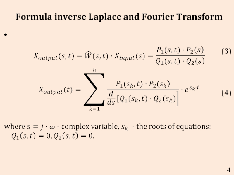
- 4. Formula inverse Laplace and Fourier Transform 4
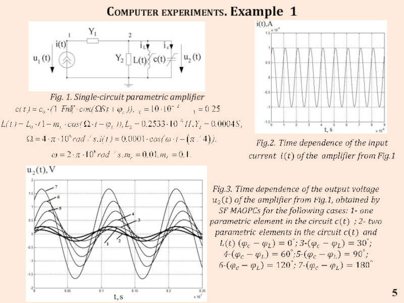
- 5. 5 Computer experiments. Example 1 Fig. 1. Single-circuit parametric amplifier
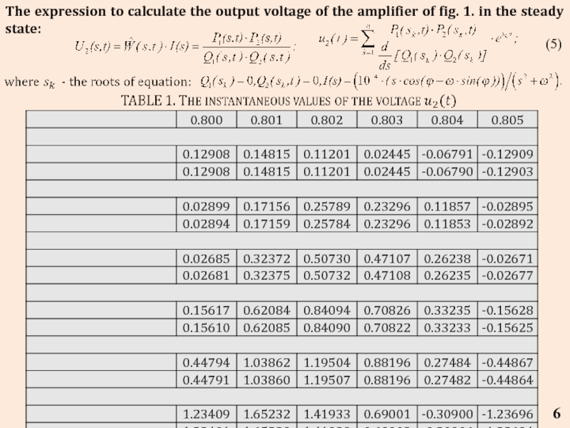
- 6. The expression to calculate the output voltage
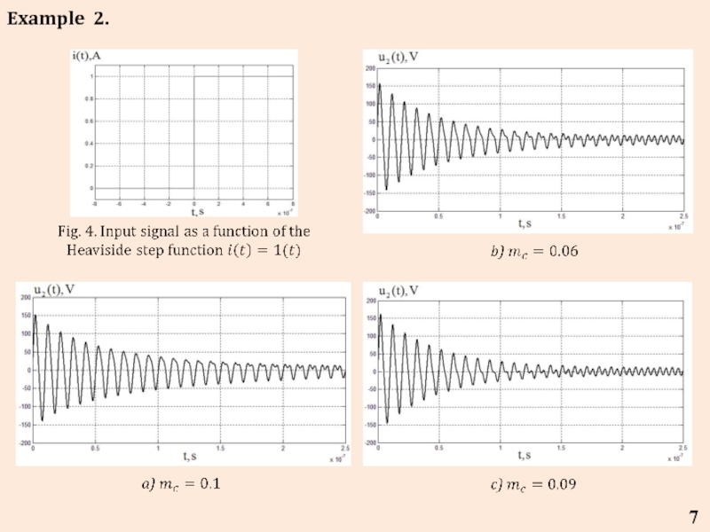
- 7. 7 Example 2.
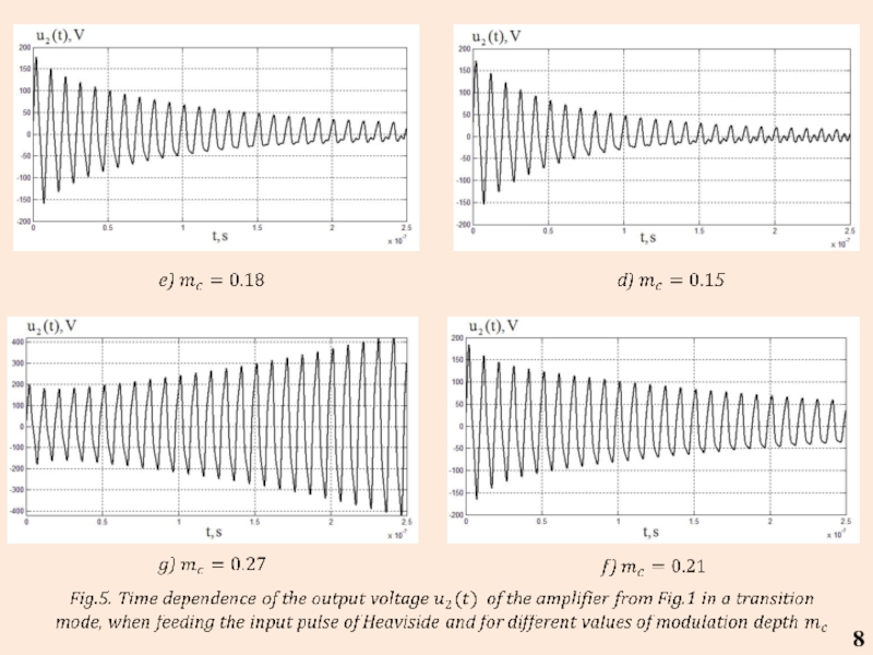
- 8. 8
- 9. The expression to calculate the output voltage
- 10. The program of calculation of output variables
- 11. Xop_out02=factor(Xop_out01); [P2,Q2]=numden(Xop_out02); %% виділяємо окремо чисельник
- 12. CONCLUSIONS The coincidence of
- 13. Thank you for attention
Слайд 1Lviv Polytechnic National University
Institute of Telecommunications, Radioelectronics and Electronic Engineering
Department of
«The adequacy of analysis of linear periodically-time-variable circuits by the frequency symbolic method in the time domain»
DSc, Prof. Yuriy Shapovalov,
DSc, Prof. Bohdan Mandziy,
Ph.D. Dariya Bachyk,
B.Eng. Marian Turyk.
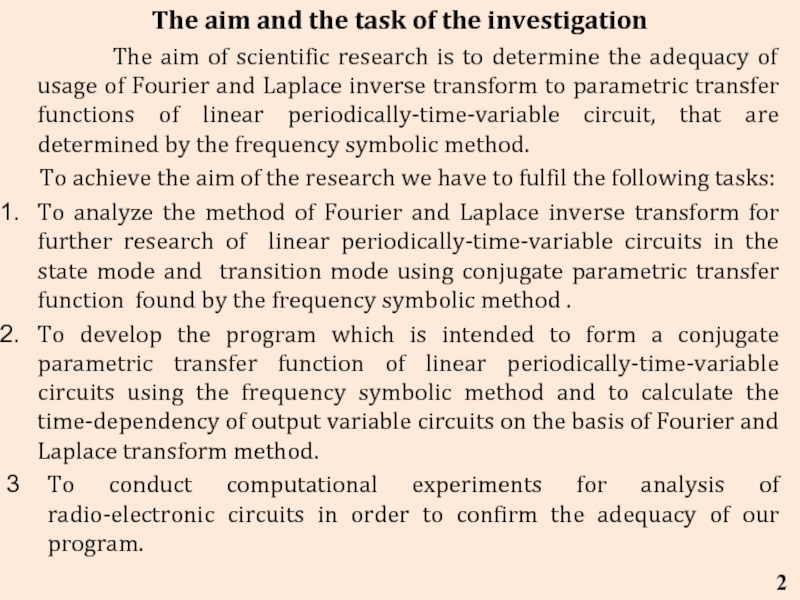
Слайд 2 The aim of scientific
To achieve the aim of the research we have to fulfil the following tasks:
To analyze the method of Fourier and Laplace inverse transform for further research of linear periodically-time-variable circuits in the state mode and transition mode using conjugate parametric transfer function found by the frequency symbolic method .
To develop the program which is intended to form a conjugate parametric transfer function of linear periodically-time-variable circuits using the frequency symbolic method and to calculate the time-dependency of output variable circuits on the basis of Fourier and Laplace transform method.
To conduct computational experiments for analysis of radio-electronic circuits in order to confirm the adequacy of our program.
2
The aim and the task of the investigation
Слайд 3
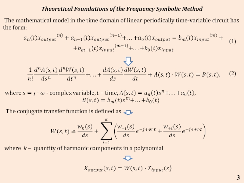
Theoretical Foundations of the Frequency Symbolic Method
3
The conjugate transfer function
where k – quantity of harmonic components in a polynomial
(1)
(2)
The mathematical model in the time domain of linear periodically time-variable circuit has the form:
Слайд 6The expression to calculate the output voltage of the amplifier of
(5)
6
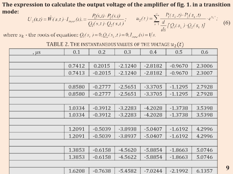
Слайд 9The expression to calculate the output voltage of the amplifier of
(6)
9
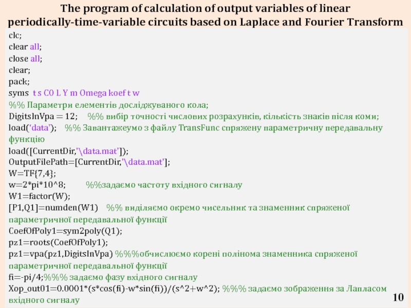
Слайд 10The program of calculation of output variables of linear periodically-time-variable circuits
10
clc;
clear all;
close all;
clear;
pack;
syms t s C0 L Y m Omega koef t w
%% Параметри елементів досліджуваного кола;
DigitsInVpa = 12; %% вибір точності числових розрахунків, кількість знаків після коми;
load(‘data'); %% Завантажеумо з файлу TransFunc спряжену параметричну передавальну функцію
load([CurrentDir,'\data.mat']);
OutputFilePath=[CurrentDir,'\data.mat'];
W=TF{7,4};
w=2*pi*10^8; %%задаємо частоту вхідного сигналу
W1=factor(W);
[P1,Q1]=numden(W1) %% виділяємо окремо чисельник та знаменник спряженої параметричної передавальної функції
CoefOfPoly1=sym2poly(Q1);
pz1=roots(CoefOfPoly1);
pz1=vpa(pz1,DigitsInVpa) %%%обчислюємо корені полінома знаменника спряженої параметричної передавальної функції
fi=-pi/4;%%% задаємо фазу вхідного сигналу
Xop_out01=0.0001*(s*cos(fi)-w*sin(fi))/(s^2+w^2); %%% задаємо зображення за Лапласом вхідного сигналу
10
Слайд 11Xop_out02=factor(Xop_out01);
[P2,Q2]=numden(Xop_out02); %% виділяємо окремо чисельник та знаменник зображення за Лапласом
CoefOfPoly2=sym2poly(Q2);
pz2=roots(CoefOfPoly2);
pz2=vpa(pz2,DigitsInVpa) %% обчислюємо корені полінома знаменника зображення за Лапласом вхідного сигналу
%%підставляємо одержані корені у формулу перетворення Лапласа
X_out_p=((P1*P2)/(diff(Q1*Q2,s,1)))*exp(s*t);
X_out=0;
for n=1:18 %кількість коренів pz1
X_out_sub11(n)=subs(X_out_p,s,pz1(n));
X_out11=X_out+...
X_out_sub11(n);
end
X_out=0;
for k=1:2 %кількість коренів pz2
X_out_sub22(k)=subs(X_out_p,s,pz2(k));
X_out22=X_out+...
X_out_sub22(k);
X_out=X_out11+X_out22;
end
save(OutputFilePath,'X_out','-append');
11
Слайд 12 CONCLUSIONS
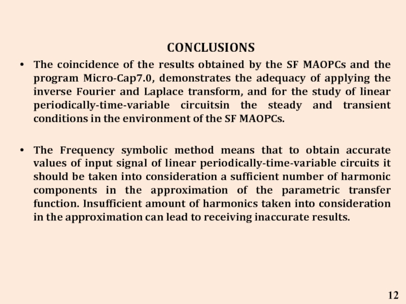
The coincidence of the results obtained by the
The Frequency symbolic method means that to obtain accurate values of input signal of linear periodically-time-variable circuits it should be taken into consideration a sufficient number of harmonic components in the approximation of the parametric transfer function. Insufficient amount of harmonics taken into consideration in the approximation can lead to receiving inaccurate results.
12
![Xop_out02=factor(Xop_out01);[P2,Q2]=numden(Xop_out02); %% виділяємо окремо чисельник та знаменник зображення за Лапласом вхідного сигналуCoefOfPoly2=sym2poly(Q2);pz2=roots(CoefOfPoly2);pz2=vpa(pz2,DigitsInVpa) %% обчислюємо корені](/img/tmb/4/325910/bf46ef0f40bf9925783e1ebc5dacbdbf-800x.jpg)
