- Главная
- Разное
- Дизайн
- Бизнес и предпринимательство
- Аналитика
- Образование
- Развлечения
- Красота и здоровье
- Финансы
- Государство
- Путешествия
- Спорт
- Недвижимость
- Армия
- Графика
- Культурология
- Еда и кулинария
- Лингвистика
- Английский язык
- Астрономия
- Алгебра
- Биология
- География
- Детские презентации
- Информатика
- История
- Литература
- Маркетинг
- Математика
- Медицина
- Менеджмент
- Музыка
- МХК
- Немецкий язык
- ОБЖ
- Обществознание
- Окружающий мир
- Педагогика
- Русский язык
- Технология
- Физика
- Философия
- Химия
- Шаблоны, картинки для презентаций
- Экология
- Экономика
- Юриспруденция
VSM(Vehicle Stability Management) презентация
Содержание
- 1. VSM(Vehicle Stability Management)
- 3. 1. SCC Sensor and Control Module 2.
- 4. SCC (Smart Cruise Control) ▶ Disengaged
- 5. Constant Speed Set speed :
- 6. SCC Sensor Alignment ● Reason for
- 7. 1. Start rotation of rear wheel 2.
- 8. The mirror is perpendicular to the ground
- 9. ESC
- 10. ▶ ABS
- 11. ESC Specification
- 12. Sensor Cluster (Module) Pressure Sensor Wheel Speed
- 13. Sensor cluster ▶ Included Sensor: Yaw rate
- 14. Sensor cluster Failsafe
- 15. Pressure sensor ▶ W/O SCC: 1EA
- 16. Wheel speed sensor & HECM [WSS –
- 17. SAS (Steering Angle Sensor) ▶ Type
- 18. ▶ SAS Alignment ①
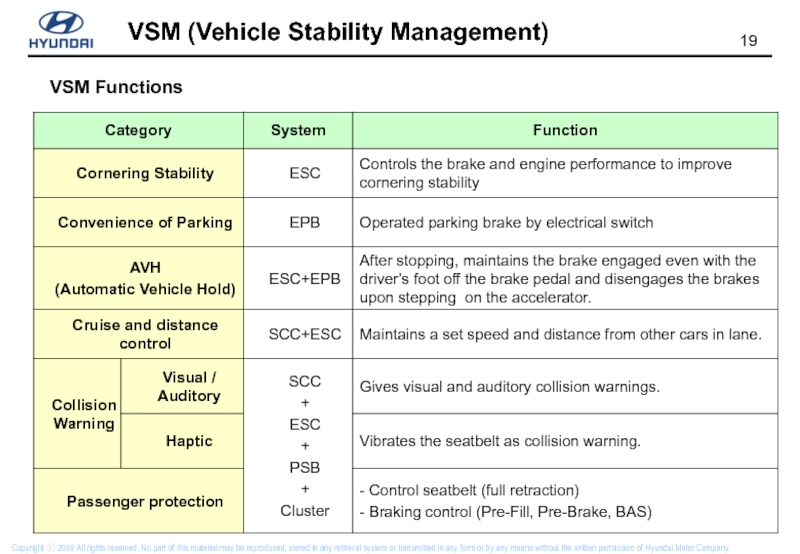
- 19. VSM Functions
- 20. 0,3g Pre-Brake Prefill Deceleration
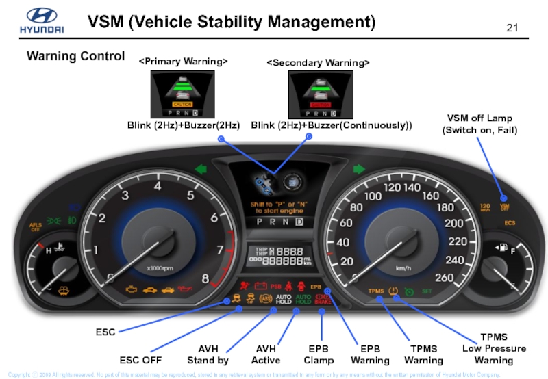
- 21. VSM off Lamp (Switch on, Fail)
Слайд 1VSM
(Vehicle Stability Management)
Centennial / Equus
Copyright ⓒ 2009 All rights reserved.
Слайд 2
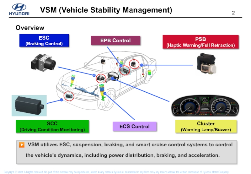
SCC
(Driving Condition Monitoring)
ESC
(Braking Control)
PSB
(Haptic Warning/Full Retraction)
Cluster
(Warning Lamp/Buzzer)
Overview
▶ VSM utilizes ESC, suspension,
the vehicle’s dynamics, including power distribution, braking, and acceleration.
EPB Control
ECS Control
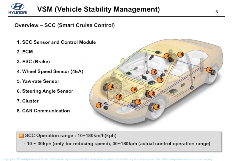
Слайд 31. SCC Sensor and Control Module
2. ECM
3. ESC (Brake)
4. Wheel Speed
5. Yaw-rate Sensor
6. Steering Angle Sensor
7. Cluster
8. CAN Communication
Overview – SCC (Smart Cruise Control)
▶ SCC Operation range : 10~180km/h(kph)
- 10 ~ 30kph (only for reducing speed), 30~180kph (actual control operation range)
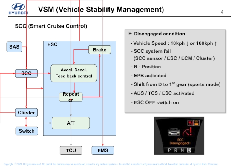
Слайд 4SCC (Smart Cruise Control)
▶ Disengaged condition
- Vehicle Speed
- SCC system fail
(SCC sensor / ESC / ECM / Cluster)
- R - Position
- EPB activated
- Shift from D to 1st gear (sports mode)
- ABS / TCS / ESC activated
- ESC OFF switch on
Слайд 5Constant Speed
Set speed : 100km/h
Host vehicle speed :
Reduce Speed
Set speed : 100km/h
Relevant object : 80km/h
Host vehicle speed :
→ reduce to 80km/h
Maintain distance
Set speed : 100km/h
Relevant object : 80km/h
Host vehicle speed : 80km/h
Acceleration
Set speed : 100km/h
Host vehicle speed :
→ increase to 100km/h
SCC Driving Mode
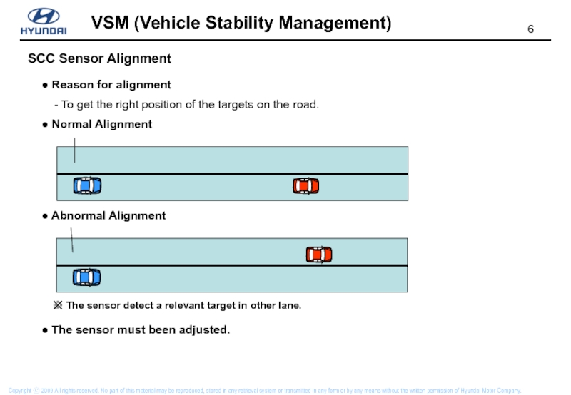
Слайд 6SCC Sensor Alignment
● Reason for alignment
- To get
● Normal Alignment
● Abnormal Alignment
※ The sensor detect a relevant target in other lane.
● The sensor must been adjusted.
Слайд 71. Start rotation of rear wheel
2. Fix dynamometer brake
▶ Start rotation
▶ Rear axis is parallel to dynamometer axis
▶ Vehicle thrust vector is perpendicular to the mirror
SCC Sensor Alignment
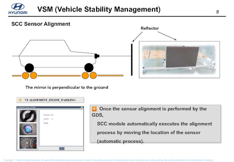
Слайд 8The mirror is perpendicular to the ground
Reflector
SCC Sensor Alignment
▶ Once
SCC module automatically executes the alignment
process by moving the location of the sensor
(automatic process).
Слайд 10
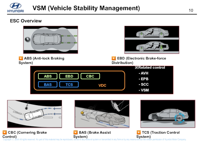
▶ ABS (Anti-lock Braking System)
▶ EBD (Electronic Brake-force Distribution)
▶ CBC (Cornering
▶ BAS (Brake Assist System)
▶ TCS (Traction Control System)
ESC Overview
Слайд 12Sensor Cluster (Module)
Pressure Sensor
Wheel Speed Sensor
Solenoid Valve
[CAN Communication]
◈ Input
-
◈ Output
- Warning Lamp (ESC / VSM)
- Indicator (ESC)
Motor Pump
Brake Switch
ESC OFF Switch
CAN
AVH / VSM Switch
Stop Lamp Relay
Wheel Speed Sensor Output
H
E
C
U
Inputs and Outputs
※ The signal of SAS is transmitted via power train high speed CAN.
Слайд 13Sensor cluster
▶ Included Sensor: Yaw rate / Lateral / Longitudinal G
※ It has a function of self-diagnosis and sends the output
signal to ESC via private CAN line.
Слайд 16Wheel speed sensor & HECM
[WSS – Front ; built in the
▶ Type
- Front : Hall IC type
- Rear : Magnetic type
▶ Spec.: 7mA ~14mA
[HECM]
[WSS – Rear]
Слайд 17SAS (Steering Angle Sensor)
▶ Type
- Contact-less type
- Range: -780˚ ~ + 780˚
- ESC Module receives steering wheel angle
sensor signals from powertrain CAN.
[SAS]
IGN
GND
SAS
ESC
CAN HI
CAN LOW
Powertrain CAN
Слайд 18▶ SAS Alignment
① Perform front wheels alignment and
② Connect the scanner
③ Perform SAS calibration menu
④ After disconnect scanner and confirm
- Road Test : Turn left once and right once and warning light must not go off
System Maintenance
Слайд 20
0,3g
Pre-Brake
Prefill
Deceleration rate variation
BAS
Primary Warning
(Cluster)
Time
With VSM
Without VSM
Foot movement
(Accel → Brake)
Threat recognition
Brake pedal
Seatbelt
vibration
Retraction
Deceleration rate
Max.
Deceleration rate
Required
Deceleration rate
Secondary Warning
(Cluster + seatbelt vibration)
Braking Control
Слайд 21VSM off Lamp
(Switch on, Fail)
Blink (2Hz)+Buzzer(2Hz)
Blink (2Hz)+Buzzer(Continuously))
AVH
Stand by
AVH
Active
EPB
Warning
ESC
ESC
EPB
Clamp
TPMS
Warning
TPMS
Low Pressure
Warning
Warning Control




![Sensor Cluster (Module)Pressure SensorWheel Speed SensorSolenoid Valve[CAN Communication]◈ Input - SAS, Gear Position…◈ Output -](/img/tmb/1/81334/460979d79ed3b4c6f25330366fc1ab31-800x.jpg)


![Wheel speed sensor & HECM[WSS – Front ; built in the hub bearing] ▶ Type](/img/tmb/1/81334/023879d01e8f0598e94819d75da9c4a6-800x.jpg)


