- Главная
- Разное
- Дизайн
- Бизнес и предпринимательство
- Аналитика
- Образование
- Развлечения
- Красота и здоровье
- Финансы
- Государство
- Путешествия
- Спорт
- Недвижимость
- Армия
- Графика
- Культурология
- Еда и кулинария
- Лингвистика
- Английский язык
- Астрономия
- Алгебра
- Биология
- География
- Детские презентации
- Информатика
- История
- Литература
- Маркетинг
- Математика
- Медицина
- Менеджмент
- Музыка
- МХК
- Немецкий язык
- ОБЖ
- Обществознание
- Окружающий мир
- Педагогика
- Русский язык
- Технология
- Физика
- Философия
- Химия
- Шаблоны, картинки для презентаций
- Экология
- Экономика
- Юриспруденция
Networking Basics презентация
Содержание
- 1. Networking Basics
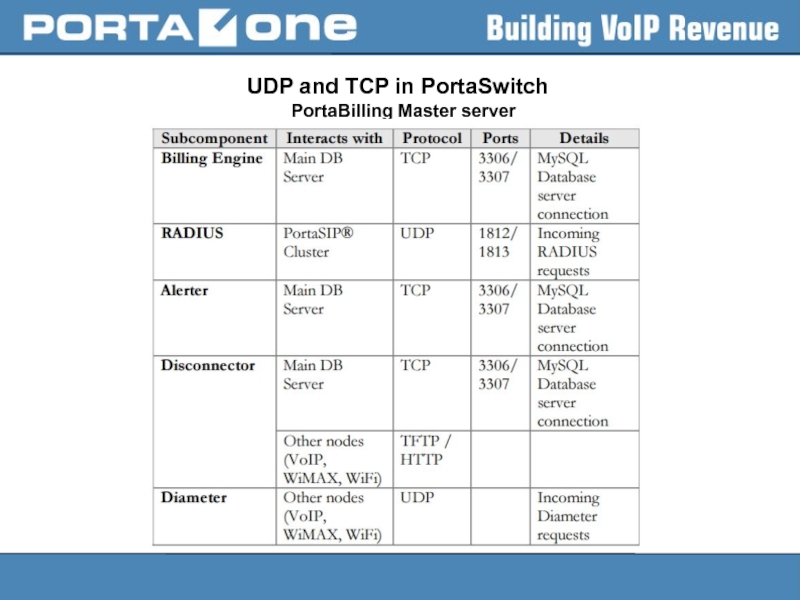
- 3. UDP vs TCP (usage in PortaSwitch)
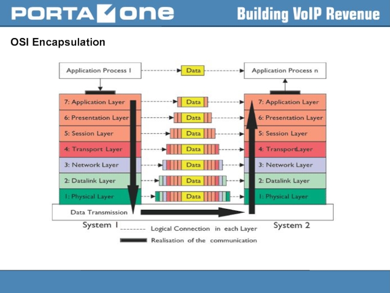
- 5. OSI Encapsulation
- 6. OSI (Open Source Interconnection) 7 Layer Model
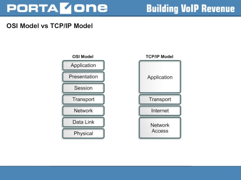
- 7. OSI Model vs TCP/IP Model
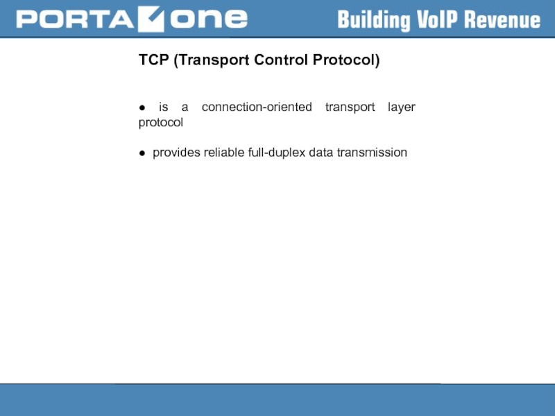
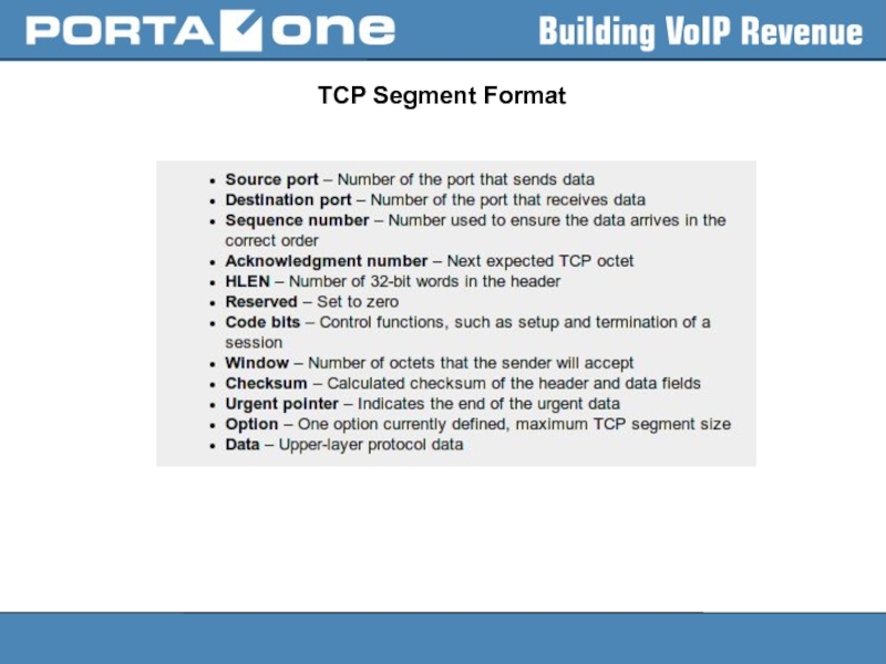
- 8. TCP (Transport Control Protocol) ●
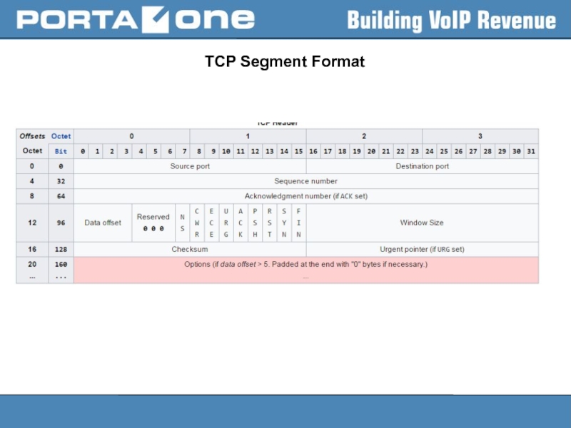
- 9. TCP Segment Format
- 10. TCP Segment Format
- 11. TCP session initiation
- 12. Well-known services that use TCP
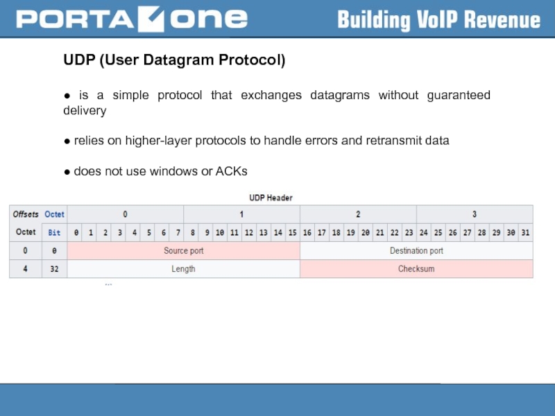
- 13. UDP (User Datagram Protocol) ● is
- 14. Well-known services that use UDP
- 15. UDP and TCP in PortaSwitch
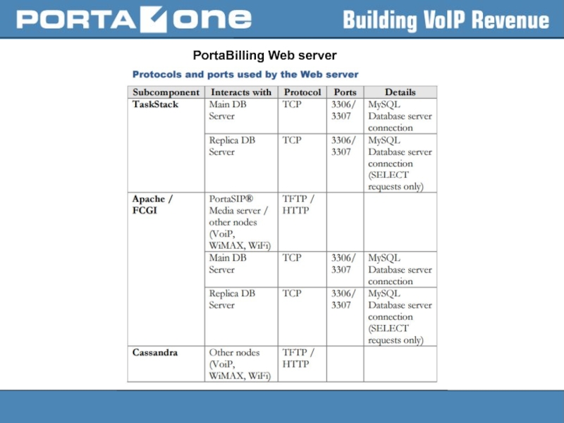
- 16. PortaBilling Web server
- 17. PortaSIP Cluster
- 18. Routing (static, dynamic, gateways) Routing is
- 19. Routers A router is a networking
- 20. Routing table Routing table is a
- 21. Linux PC operating as a Router
- 22. Policy Based Routing Usually, route selection
- 23. Route Selection Kernel route search order
- 24. Using IP utility Display IP addresses
- 25. Using IP utility Display routing cache:
- 26. Using IP utility Check what route
- 27. Network Config Files ● are located
- 28. Network Configuration Files /etc/hosts –
- 29. Network Configuration Files Saving static routes
- 30. Why we should use command ‘ip’
- 31. Why we should use command ‘ip’
- 32. Channel bonding Channel bonding enables two
- 33. Bonding mode mode= Allows specifies the bonding
- 34. Bonding mode 802.3ad or 4 —
- 35. Active-backup mode hint For active-backup mode,
- 36. Manual configuration of channel bonding 1)
- 37. Manual configuration of channel bonding 3) Add
- 38. Manual configuration of channel bonding bond0 Link
- 39. Useful SYSFS commands To view all existing
- 40. Useful SYSFS commands Bonding statistics: >
- 41. Bonding parameters arp_interval= Specifies (in milliseconds) how
- 42. Bonding parameters downdelay= Specifies (in milliseconds) how
- 43. RHEL 7 peculiarities According to documentation
- 44. Network Manager In Red Hat Enterprise Linux
- 45. Terms of Network Manager NM operates
- 46. Using nmcli to manipulate with networking
- 47. Using nmcli to manipulate with networking Activate
- 48. How to disable Network Manager Add
Слайд 2
Agenda
● UDP vs TCP (usage in PortaSwitch)
● Routing (static, dynamic, gateways)
● Bonding (overview, configuration in RHEL6 & RHEL7, recommendations,
bond in net. manager)
● Network manager
Слайд 8TCP (Transport Control Protocol)
● is a connection-oriented transport layer protocol
● provides
Слайд 12Well-known services that use TCP
- FTP (20/TCP);
SSH (22/TCP);
Telnet (23/TCP);
HTTP (80/TCP);
HTTPS (443/TCP);
Слайд 13UDP (User Datagram Protocol)
● is a simple protocol that exchanges datagrams
● relies on higher-layer protocols to handle errors and retransmit data
● does not use windows or ACKs
Слайд 14Well-known services that use UDP
DNS (53/UDP);
NTP (123/UDP);
Online gaming;
Video streaming services;
RTP;
SIP;
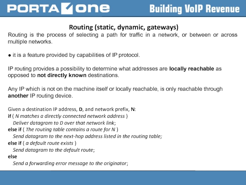
Слайд 18 Routing (static, dynamic, gateways)
Routing is the process of selecting a
● it is a feature provided by capabilities of IP protocol.
IP routing provides a possibility to determine what addresses are locally reachable as opposed to not directly known destinations.
Any IP which is not on the machine itself or locally reachable, is only reachable through another IP routing device.
Given a destination IP address, D, and network prefix, N:
if ( N matches a directly connected network address ) Deliver datagram to D over that network link; else if ( The routing table contains a route for N ) Send datagram to the next-hop address listed in the routing table; else if ( a default route exists ) Send datagram to the default route; else Send a forwarding error message to the originator;
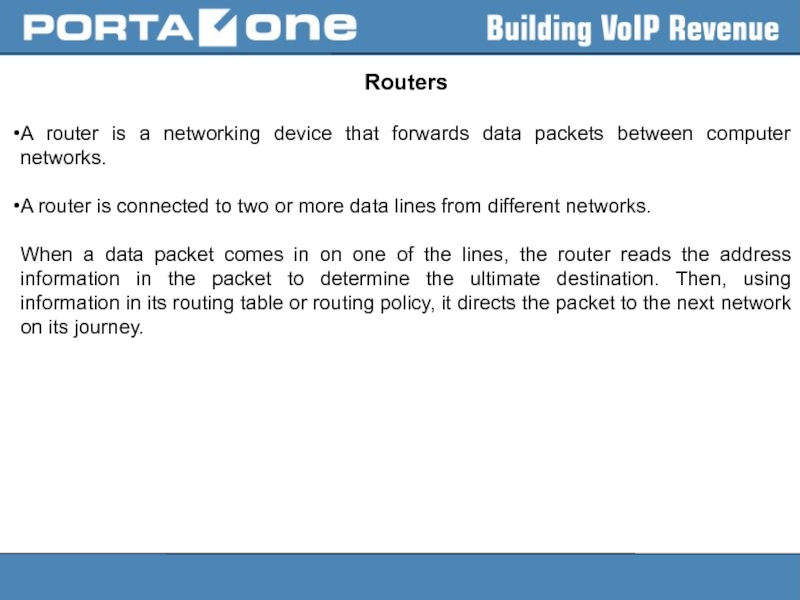
Слайд 19Routers
A router is a networking device that forwards data packets between
A router is connected to two or more data lines from different networks.
When a data packet comes in on one of the lines, the router reads the address information in the packet to determine the ultimate destination. Then, using information in its routing table or routing policy, it directs the packet to the next network on its journey.
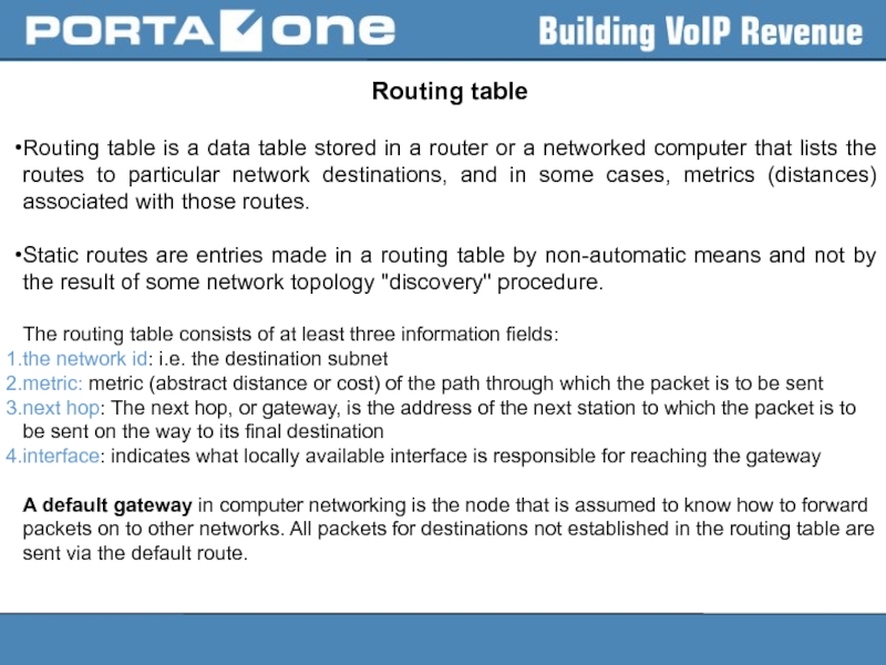
Слайд 20Routing table
Routing table is a data table stored in a router
Static routes are entries made in a routing table by non-automatic means and not by the result of some network topology "discovery" procedure.
The routing table consists of at least three information fields:
the network id: i.e. the destination subnet
metric: metric (abstract distance or cost) of the path through which the packet is to be sent
next hop: The next hop, or gateway, is the address of the next station to which the packet is to be sent on the way to its final destination
interface: indicates what locally available interface is responsible for reaching the gateway
A default gateway in computer networking is the node that is assumed to know how to forward packets on to other networks. All packets for destinations not established in the routing table are sent via the default route.
Слайд 21Linux PC operating as a Router
● allows a PC on Linux
The process of accepting and transmitting IP packets is known as forwarding.
net/ipv4/ip_forward – enables/disables forwarding globally
net/ipv4/conf/$DEV/forward – to override the global value on a particular interface
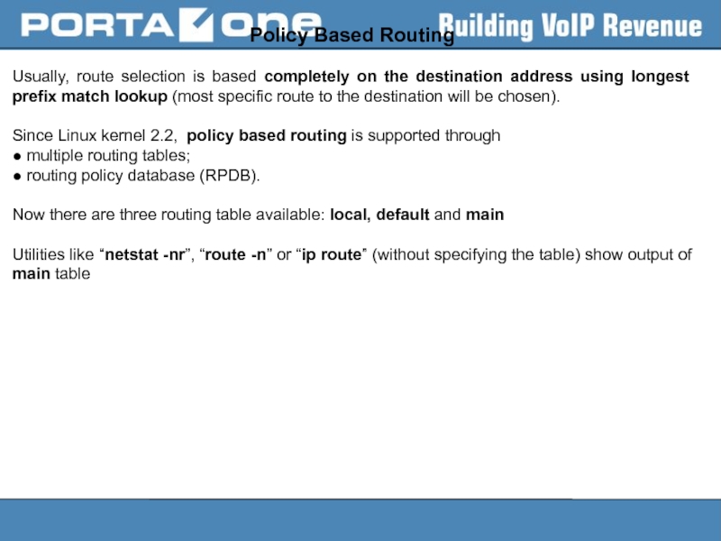
Слайд 22Policy Based Routing
Usually, route selection is based completely on the destination
Since Linux kernel 2.2, policy based routing is supported through
● multiple routing tables;
● routing policy database (RPDB).
Now there are three routing table available: local, default and main
Utilities like “netstat -nr”, “route -n” or “ip route” (without specifying the table) show output of main table
Слайд 23Route Selection
Kernel route search order is:
● first in the routing cache
●
The routing cache is a hash table used for quick access to recently used routes.
Слайд 24 Using IP utility
Display IP addresses configuration:
> ip a | grep
2: eno1:
link/ether 00:1e:c9:ef:e7:3a brd ff:ff:ff:ff:ff:ff
inet 78.40.240.208/27 brd 78.40.240.223 scope global eno1
--
3: eno2:
link/ether 00:1e:c9:ef:e7:3c brd ff:ff:ff:ff:ff:ff
inet 78.40.244.35/24 brd 78.40.244.255 scope global eno2
Display routing information (from main table):
> ip route show
default via 78.40.244.1 dev eno2
5.144.80.0/20 via 78.40.240.201 dev eno1
10.0.0.0/9 via 78.40.244.13 dev eno2
10.1.1.1 via 78.40.244.13 dev eno2
78.40.240.192/27 dev eno1 proto kernel scope link src 78.40.240.208
78.40.244.0/24 dev eno2 proto kernel scope link src 78.40.244.35
128.1.0.0/16 via 78.40.244.13 dev eno2
169.254.0.0/16 dev eno1 scope link metric 1002
Слайд 25 Using IP utility
Display routing cache:
> ip route show cache
Display routing
> ip route flush cache
Add new route:
ip route add
> ip route add default via 192.168.1.1
> ip route add 10.10.70.0/24 via 78.40.240.220 dev eno2
Note: when you add a new static route gateway must be reachable from the interface you add a static route to. So, it gateway should be from the same subnet or path to gateway should be specified beforehand in the routing table.
Delete route:
> ip route del 10.10.70.0/24 via 78.40.240.220 dev eno2
Change route:
> ip route change default via 78.40.244.2 dev eno2
Слайд 26 Using IP utility
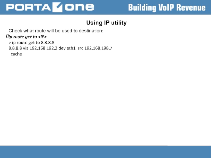
Check what route will be used to destination:
ip
> ip route get to 8.8.8.8
8.8.8.8 via 192.168.192.2 dev eth1 src 192.168.198.7
cache
Слайд 27
Network Config Files
● are located in are located in the /etc/sysconfig/network-scripts/ directory
● three
– Interface configuration files
– Interface control scripts
– Network function files
Слайд 28
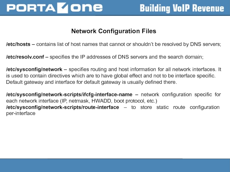
Network Configuration Files
/etc/hosts – contains list of host names that cannot
/etc/resolv.conf – specifies the IP addresses of DNS servers and the search domain;
/etc/sysconfig/network – specifies routing and host information for all network interfaces. It is used to contain directives which are to have global effect and not to be interface specific.
Default gateway and interface for default gateway is usually defined there.
/etc/sysconfig/network-scripts/ifcfg-interface-name – network configuration specific for each network interface (IP, netmask, HWADD, boot protocol, etc.)
/etc/sysconfig/network-scripts/route-interface – to store static route configuration per-interface
Слайд 29Network Configuration Files
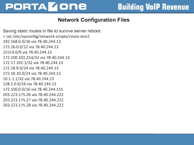
Saving static routes in file to survive server reboot:
>
192.168.0.0/16 via 78.40.244.13
172.16.0.0/12 via 78.40.244.13
10.0.0.0/9 via 78.40.244.13
172.100.101.254/32 via 78.40.244.13
172.17.192.1/32 via 78.40.244.13
172.18.9.0/24 via 78.40.244.13
172.18.10.0/24 via 78.40.244.13
10.1.1.1/32 via 78.40.244.13
128.1.0.0/16 via 78.40.244.13
172.100.0.0/16 via 78.40.244.115
203.223.175.26 via 78.40.244.222
203.223.175.27 via 78.40.244.222
203.223.175.28 via 78.40.244.222
Слайд 30Why we should use command ‘ip’
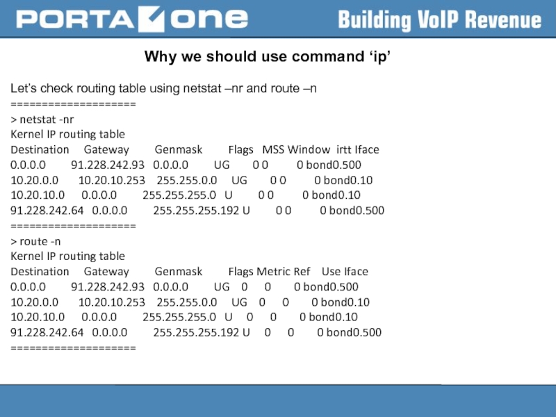
Let’s check routing table using netstat
====================
> netstat -nr
Kernel IP routing table
Destination Gateway Genmask Flags MSS Window irtt Iface
0.0.0.0 91.228.242.93 0.0.0.0 UG 0 0 0 bond0.500
10.20.0.0 10.20.10.253 255.255.0.0 UG 0 0 0 bond0.10
10.20.10.0 0.0.0.0 255.255.255.0 U 0 0 0 bond0.10
91.228.242.64 0.0.0.0 255.255.255.192 U 0 0 0 bond0.500
====================
> route -n
Kernel IP routing table
Destination Gateway Genmask Flags Metric Ref Use Iface
0.0.0.0 91.228.242.93 0.0.0.0 UG 0 0 0 bond0.500
10.20.0.0 10.20.10.253 255.255.0.0 UG 0 0 0 bond0.10
10.20.10.0 0.0.0.0 255.255.255.0 U 0 0 0 bond0.10
91.228.242.64 0.0.0.0 255.255.255.192 U 0 0 0 bond0.500
====================
Слайд 31Why we should use command ‘ip’
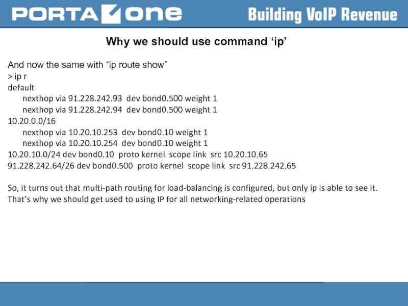
And now the same with “ip
> ip r
default
nexthop via 91.228.242.93 dev bond0.500 weight 1
nexthop via 91.228.242.94 dev bond0.500 weight 1
10.20.0.0/16
nexthop via 10.20.10.253 dev bond0.10 weight 1
nexthop via 10.20.10.254 dev bond0.10 weight 1
10.20.10.0/24 dev bond0.10 proto kernel scope link src 10.20.10.65
91.228.242.64/26 dev bond0.500 proto kernel scope link src 91.228.242.65
So, it turns out that multi-path routing for load-balancing is configured, but only ip is able to see it.
That’s why we should get used to using IP for all networking-related operations
Слайд 32Channel bonding
Channel bonding enables two or more network interfaces to act
The Linux bonding driver provides a method for aggregating multiple network interfaces into a single logical "bonded" interface. The behavior of the bonded interfaces depends upon the mode; generally speaking, modes provide either hot standby or load balancing services.
Additionally, link integrity monitoring is performed.
Слайд 33Bonding mode
mode=
Allows specifies the bonding policy. The can be one
balance-rr or 0 — Sets a round-robin policy for fault tolerance and load balancing. Transmissions are received and sent out sequentially on each bonded slave interface beginning with the first one available.
active-backup or 1 — Sets an active-backup policy for fault tolerance. Transmissions are received and sent out via the first available bonded slave interface. Another bonded slave interface is only used if the active bonded slave interface fails.
balance-xor or 2 — Sets an XOR (exclusive-or) policy for fault tolerance and load balancing. Using this method, the interface matches up the incoming request's MAC address with the MAC address for one of the slave NICs. Once this link is established, transmissions are sent out sequentially beginning with the first available interface.
broadcast or 3 — Sets a broadcast policy for fault tolerance. All transmissions are sent on all slave interfaces.
Слайд 34Bonding mode
802.3ad or 4 — Sets an IEEE 802.3ad dynamic link
balance-tlb or 5 — Sets a Transmit Load Balancing (TLB) policy for fault tolerance and load balancing. The outgoing traffic is distributed according to the current load on each slave interface. Incoming traffic is received by the current slave. If the receiving slave fails, another slave takes over the MAC address of the failed slave. This mode is only suitable for local addresses known to the kernel bonding module and therefore cannot be used behind a bridge with virtual machines.
balance-alb or 6 — Sets an Adaptive Load Balancing (ALB) policy for fault tolerance and load balancing. Includes transmit and receive load balancing for IPv4 traffic. Receive load balancing is achieved through ARP negotiation. This mode is only suitable for local addresses known to the kernel bonding module and therefore cannot be used behind a bridge with virtual machines.
Слайд 35Active-backup mode hint
For active-backup mode, Linux kernel sets the same MAC
For example:
first (primary) slave interface has HWADDR: xx.xx.xx.xx
second slave interface - HWADDR: yy.yy.yy.yy
BUT "ip a" or “ifconfig” will show that both enslaved interfaces and bond interface have the same MAC xx.xx.xx.xx
Слайд 36Manual configuration of channel bonding
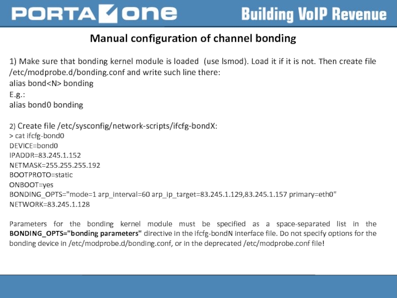
1) Make sure that bonding kernel module
alias bond
E.g.:
alias bond0 bonding
2) Create file /etc/sysconfig/network-scripts/ifcfg-bondX:
> cat ifcfg-bond0
DEVICE=bond0
IPADDR=83.245.1.152
NETMASK=255.255.255.192
BOOTPROTO=static
ONBOOT=yes
BONDING_OPTS="mode=1 arp_interval=60 arp_ip_target=83.245.1.129,83.245.1.157 primary=eth0"
NETWORK=83.245.1.128
Parameters for the bonding kernel module must be specified as a space-separated list in the BONDING_OPTS="bonding parameters" directive in the ifcfg-bondN interface file. Do not specify options for the bonding device in /etc/modprobe.d/bonding.conf, or in the deprecated /etc/modprobe.conf file!
Слайд 37Manual configuration of channel bonding
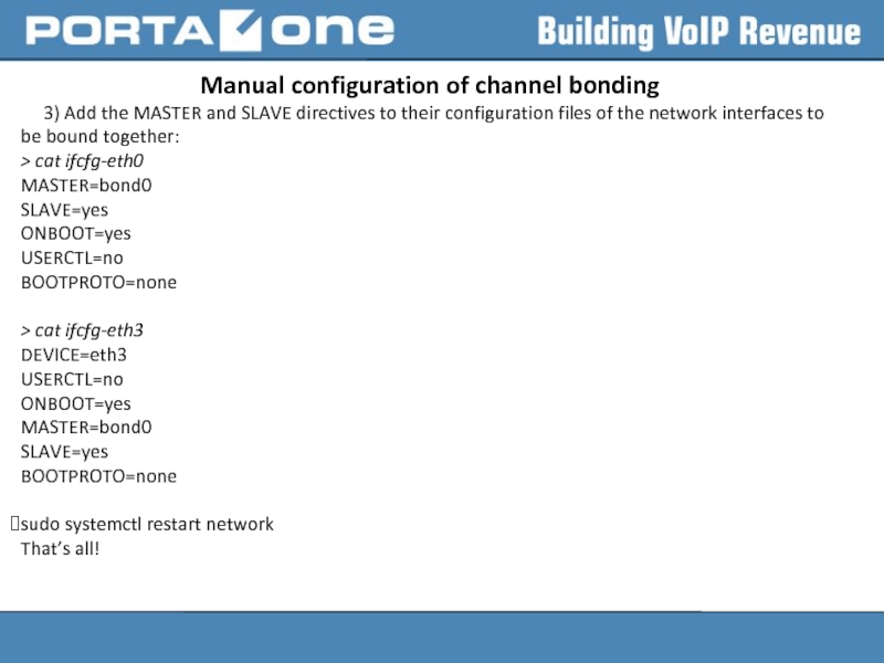
3) Add the MASTER and SLAVE directives
> cat ifcfg-eth0
MASTER=bond0
SLAVE=yes
ONBOOT=yes
USERCTL=no
BOOTPROTO=none
> cat ifcfg-eth3
DEVICE=eth3
USERCTL=no
ONBOOT=yes
MASTER=bond0
SLAVE=yes
BOOTPROTO=none
sudo systemctl restart network
That’s all!
Слайд 38Manual configuration of channel bonding
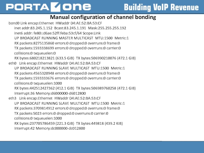
bond0 Link encap:Ethernet HWaddr D4:AE:52:BA:53:CF
inet addr:83.245.1.152
inet6 addr: fe80::d6ae:52ff:feba:53cf/64 Scope:Link
UP BROADCAST RUNNING MASTER MULTICAST MTU:1500 Metric:1
RX packets:8275135860 errors:0 dropped:0 overruns:0 frame:0
TX packets:1593338699 errors:0 dropped:0 overruns:0 carrier:0
collisions:0 txqueuelen:0
RX bytes:680218213821 (633.5 GiB) TX bytes:506990210076 (472.1 GiB)
eth0 Link encap:Ethernet HWaddr D4:AE:52:BA:53:CF
UP BROADCAST RUNNING SLAVE MULTICAST MTU:1500 Metric:1
RX packets:4565320948 errors:0 dropped:0 overruns:0 frame:0
TX packets:1593333676 errors:0 dropped:0 overruns:0 carrier:0
collisions:0 txqueuelen:1000
RX bytes:442512427362 (412.1 GiB) TX bytes:506989760258 (472.1 GiB)
Interrupt:36 Memory:d6000000-d6012800
eth3 Link encap:Ethernet HWaddr D4:AE:52:BA:53:CF
UP BROADCAST RUNNING SLAVE MULTICAST MTU:1500 Metric:1
RX packets:3709814912 errors:0 dropped:0 overruns:0 frame:0
TX packets:5023 errors:0 dropped:0 overruns:0 carrier:0
collisions:0 txqueuelen:1000
RX bytes:237705786459 (221.3 GiB) TX bytes:449818 (439.2 KiB)
Interrupt:42 Memory:dc000000-dc012800
Слайд 39Useful SYSFS commands
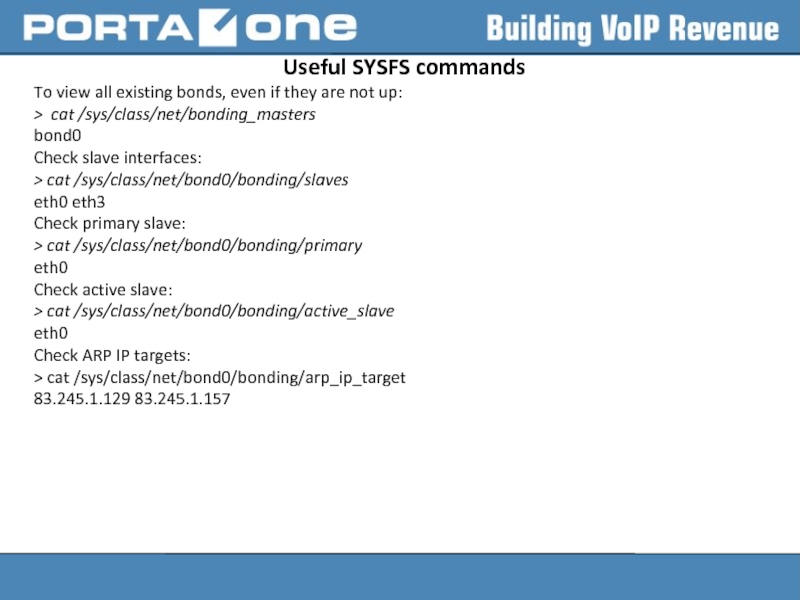
To view all existing bonds, even if they are
> cat /sys/class/net/bonding_masters
bond0
Check slave interfaces:
> cat /sys/class/net/bond0/bonding/slaves
eth0 eth3
Check primary slave:
> cat /sys/class/net/bond0/bonding/primary
eth0
Check active slave:
> cat /sys/class/net/bond0/bonding/active_slave
eth0
Check ARP IP targets:
> cat /sys/class/net/bond0/bonding/arp_ip_target
83.245.1.129 83.245.1.157
Слайд 40Useful SYSFS commands
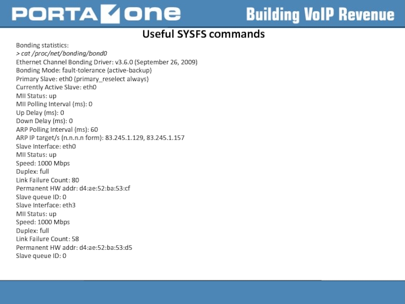
Bonding statistics:
> cat /proc/net/bonding/bond0
Ethernet Channel Bonding Driver: v3.6.0
Bonding Mode: fault-tolerance (active-backup)
Primary Slave: eth0 (primary_reselect always)
Currently Active Slave: eth0
MII Status: up
MII Polling Interval (ms): 0
Up Delay (ms): 0
Down Delay (ms): 0
ARP Polling Interval (ms): 60
ARP IP target/s (n.n.n.n form): 83.245.1.129, 83.245.1.157
Slave Interface: eth0
MII Status: up
Speed: 1000 Mbps
Duplex: full
Link Failure Count: 80
Permanent HW addr: d4:ae:52:ba:53:cf
Slave queue ID: 0
Slave Interface: eth3
MII Status: up
Speed: 1000 Mbps
Duplex: full
Link Failure Count: 58
Permanent HW addr: d4:ae:52:ba:53:d5
Slave queue ID: 0
Слайд 41Bonding parameters
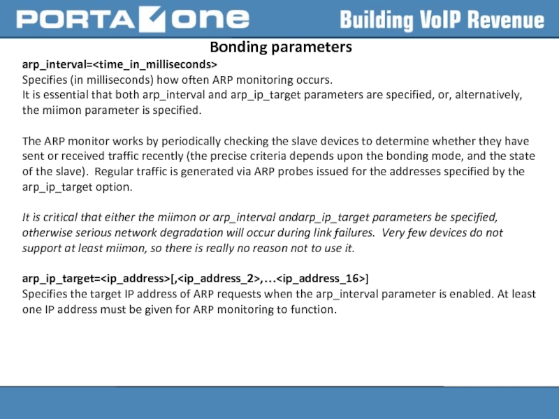
arp_interval=
Specifies (in milliseconds) how often ARP monitoring occurs.
It is essential
The ARP monitor works by periodically checking the slave devices to determine whether they have sent or received traffic recently (the precise criteria depends upon the bonding mode, and the state of the slave). Regular traffic is generated via ARP probes issued for the addresses specified by the arp_ip_target option.
It is critical that either the miimon or arp_interval andarp_ip_target parameters be specified, otherwise serious network degradation will occur during link failures. Very few devices do not support at least miimon, so there is really no reason not to use it.
arp_ip_target=
Specifies the target IP address of ARP requests when the arp_interval parameter is enabled. At least one IP address must be given for ARP monitoring to function.
Слайд 42Bonding parameters
downdelay=
Specifies (in milliseconds) how long to wait after link failure
updelay=
miimon=
Specifies (in milliseconds) how often MII link monitoring occurs.
Specifies the MII link monitoring frequency in milliseconds. This determines how often the link state of each slave is inspected for link failures. A value of zero disables MII link monitoring. A value of 100 is a good starting point.
primary=
Specifies the interface name, such as eth0, of the primary device. The primary device is the first of the bonding interfaces to be used and is not abandoned unless it fails. A string (eth0, eth2, etc) specifying which slave is the primary device. The specified device will always be the active slave while it is available. Only when the primary is off-line will alternate devices be used. This is useful when one slave is preferred over another, e.g., when one slave has higher throughput than another.
Слайд 43RHEL 7 peculiarities
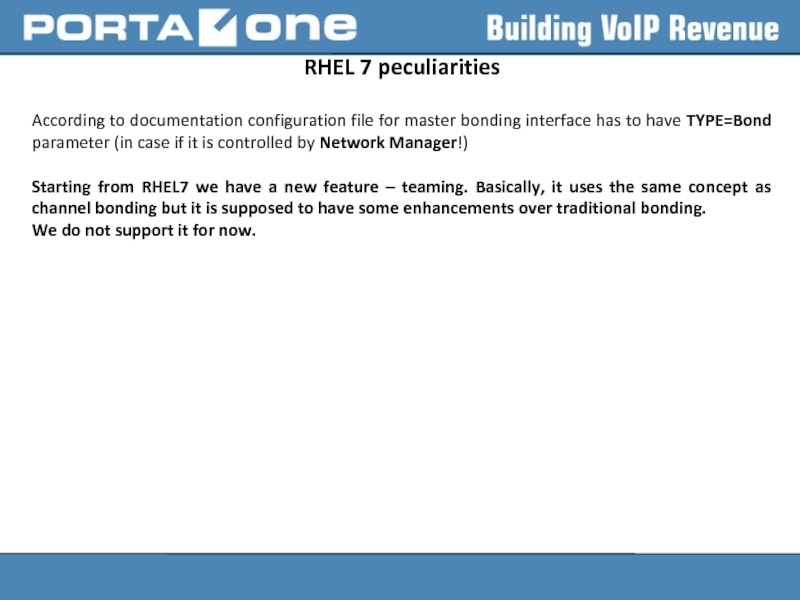
According to documentation configuration file for master bonding interface
Starting from RHEL7 we have a new feature – teaming. Basically, it uses the same concept as channel bonding but it is supposed to have some enhancements over traditional bonding.
We do not support it for now.
Слайд 44Network Manager
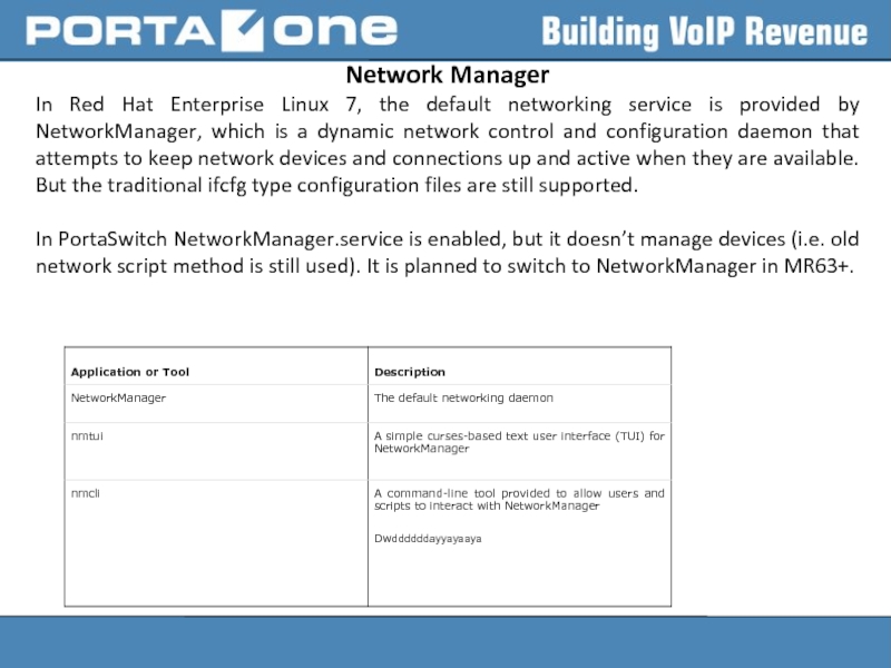
In Red Hat Enterprise Linux 7, the default networking service
In PortaSwitch NetworkManager.service is enabled, but it doesn’t manage devices (i.e. old network script method is still used). It is planned to switch to NetworkManager in MR63+.
Слайд 45Terms of Network Manager
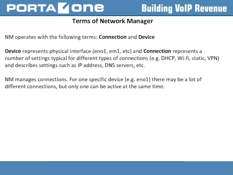
NM operates with the following terms: Connection and
Device represents physical interface (eno1, em1, etc) and Connection represents a number of settings typical for different types of connections (e.g. DHCP, Wi-fi, static, VPN) and describes settings such as IP address, DNS servers, etc.
NM manages connections. For one specific device (e.g. eno1) there may be a lot of different connections, but only one can be active at the same time.
Слайд 46Using nmcli to manipulate with networking
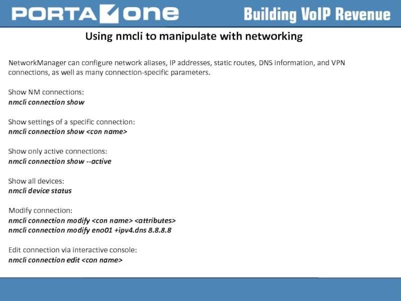
NetworkManager can configure network aliases, IP
Show NM connections:
nmcli connection show
Show settings of a specific connection:
nmcli connection show
Show only active connections:
nmcli connection show --active
Show all devices:
nmcli device status
Modify connection:
nmcli connection modify
nmcli connection modify eno01 +ipv4.dns 8.8.8.8
Edit connection via interactive console:
nmcli connection edit
Слайд 47Using nmcli to manipulate with networking
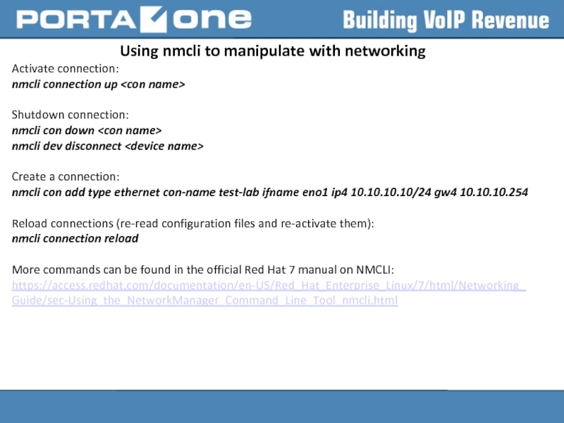
Activate connection:
nmcli connection up
Shutdown
nmcli con down
nmcli dev disconnect
Create a connection:
nmcli con add type ethernet con-name test-lab ifname eno1 ip4 10.10.10.10/24 gw4 10.10.10.254
Reload connections (re-read configuration files and re-activate them):
nmcli connection reload
More commands can be found in the official Red Hat 7 manual on NMCLI:
https://access.redhat.com/documentation/en-US/Red_Hat_Enterprise_Linux/7/html/Networking_Guide/sec-Using_the_NetworkManager_Command_Line_Tool_nmcli.html
Слайд 48How to disable Network Manager
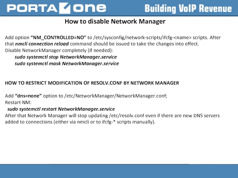
Add option “NM_CONTROLLED=NO” to /etc/sysconfig/network-scripts/ifcfg- scripts. After
Disable NetworkManager completely (if needed):
sudo systemctl stop NetworkManager.service
sudo systemctl mask NetworkManager.service
HOW TO RESTRICT MODIFICATION OF RESOLV.CONF BY NETWORK MANAGER
Add “dns=none” option to /etc/NetworkManager/NetworkManager.conf;
Restart NM:
sudo systemctl restart NetworkManager.service
After that Network Manager will stop updating /etc/resolv.conf even if there are new DNS servers added to connections (either via nmcli or to ifcfg-* scripts manually).

