- Главная
- Разное
- Дизайн
- Бизнес и предпринимательство
- Аналитика
- Образование
- Развлечения
- Красота и здоровье
- Финансы
- Государство
- Путешествия
- Спорт
- Недвижимость
- Армия
- Графика
- Культурология
- Еда и кулинария
- Лингвистика
- Английский язык
- Астрономия
- Алгебра
- Биология
- География
- Детские презентации
- Информатика
- История
- Литература
- Маркетинг
- Математика
- Медицина
- Менеджмент
- Музыка
- МХК
- Немецкий язык
- ОБЖ
- Обществознание
- Окружающий мир
- Педагогика
- Русский язык
- Технология
- Физика
- Философия
- Химия
- Шаблоны, картинки для презентаций
- Экология
- Экономика
- Юриспруденция
Message signaled interrupts презентация
Содержание
- 1. Message signaled interrupts
- 2. The ‘old’ way In order to appreciate
- 3. Multi-step communication A device signals that it
- 4. Faster, cheaper, and more Faster response to
- 5. The ‘new’ way Message Signaling allows all
- 6. Implementation The customary PCI Configuration Space is
- 7. PCI Command Register
- 8. PCI Status Register
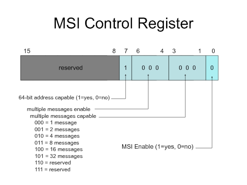
- 9. MSI Control Register
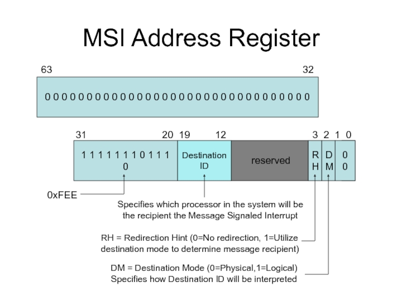
- 10. MSI Address Register 0 0 0 0
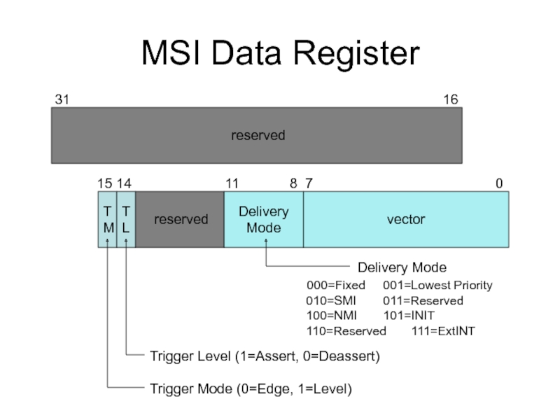
- 11. MSI Data Register reserved
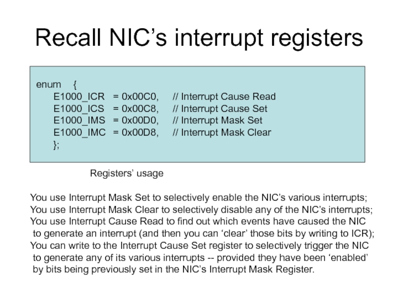
- 12. Recall NIC’s interrupt registers enum { E1000_ICR =
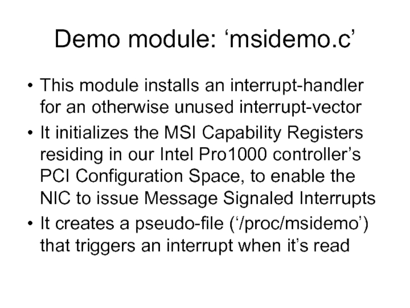
- 13. Demo module: ‘msidemo.c’ This module installs an
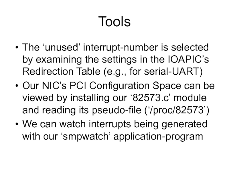
- 14. Tools The ‘unused’ interrupt-number is selected by
Слайд 1Message Signaled Interrupts
A look at our network controller’s optional capability to
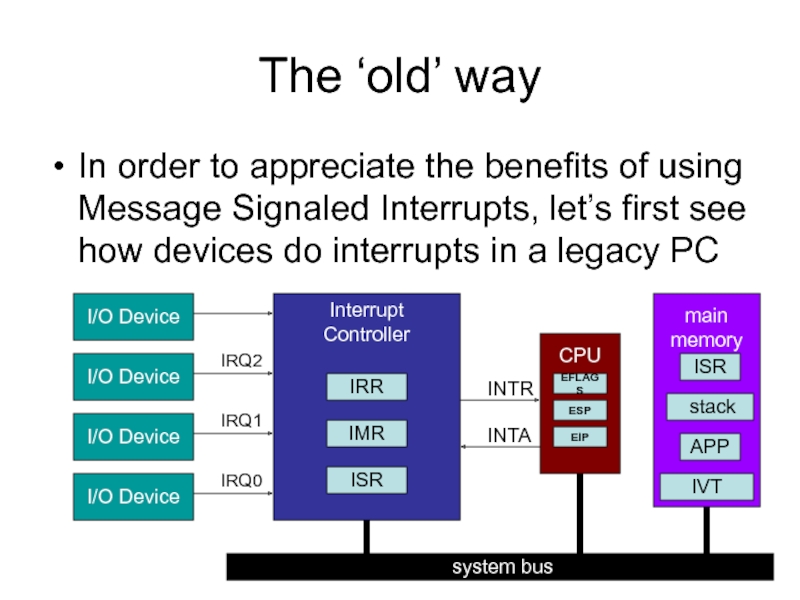
Слайд 2The ‘old’ way
In order to appreciate the benefits of using Message
Interrupt
Controller
I/O Device
I/O Device
I/O Device
I/O Device
IRR
IMR
ISR
CPU
INTR
INTA
system bus
main
memory
EFLAGS
ESP
EIP
IVT
ISR
APP
stack
IRQ0
IRQ1
IRQ2
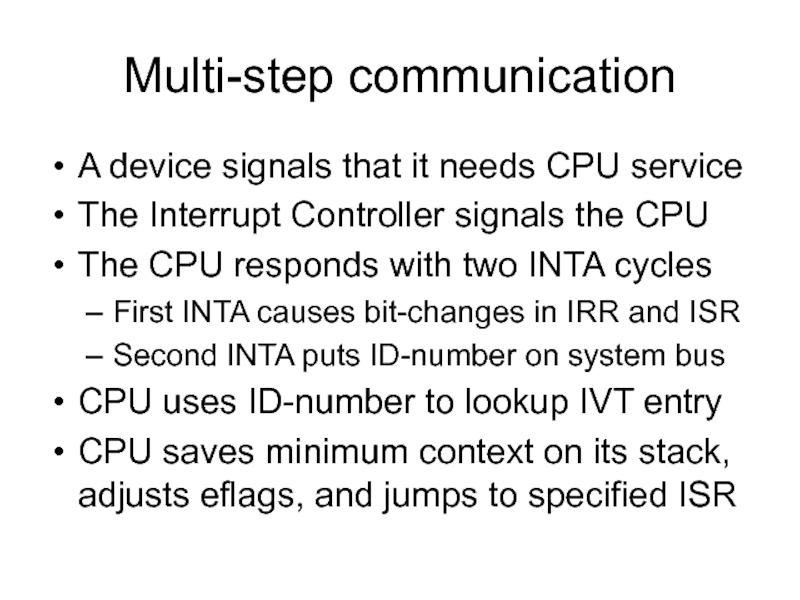
Слайд 3Multi-step communication
A device signals that it needs CPU service
The Interrupt Controller
The CPU responds with two INTA cycles
First INTA causes bit-changes in IRR and ISR
Second INTA puts ID-number on system bus
CPU uses ID-number to lookup IVT entry
CPU saves minimum context on its stack, adjusts eflags, and jumps to specified ISR
Слайд 4Faster, cheaper, and more
Faster response to interrupts is possible if the
Less expensive PCs can be manufactured if their total number of signal pins and the physical interconnections can be reduced
More devices can have their own ‘private’ interrupt(s) if signal lines aren’t required
Слайд 5The ‘new’ way
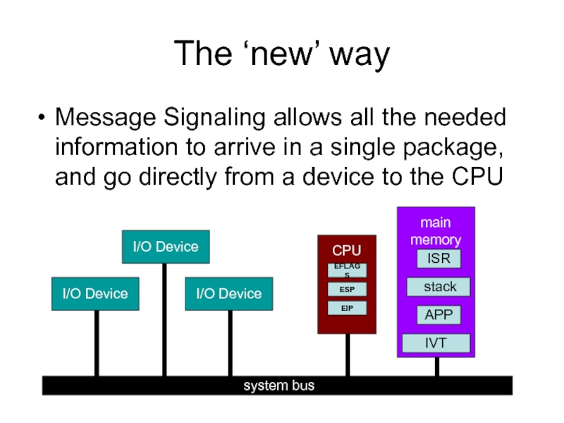
Message Signaling allows all the needed information to arrive
I/O Device
system bus
CPU
main
memory
EFLAGS
ESP
EIP
IVT
ISR
APP
stack
I/O Device
I/O Device
Слайд 6Implementation
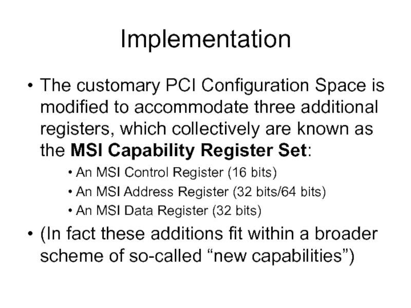
The customary PCI Configuration Space is modified to accommodate three additional
An MSI Control Register (16 bits)
An MSI Address Register (32 bits/64 bits)
An MSI Data Register (32 bits)
(In fact these additions fit within a broader scheme of so-called “new capabilities”)
Слайд 7PCI Command Register
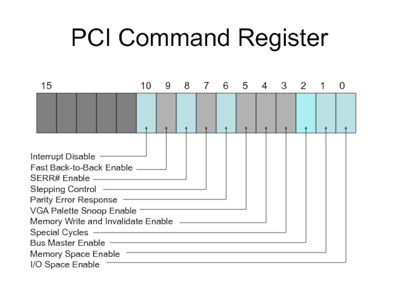
15
Interrupt Disable
Fast Back-to-Back Enable
SERR# Enable
Stepping Control
Parity Error Response
VGA Palette Snoop Enable
Memory Write and Invalidate Enable
Special Cycles
Bus Master Enable
Memory Space Enable
I/O Space Enable
Слайд 8PCI Status Register
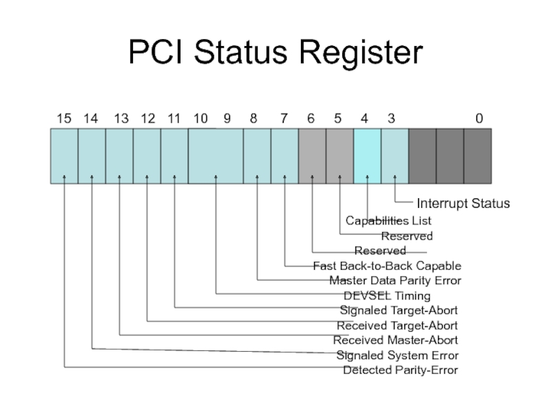
15 14 13
Interrupt Status
Capabilities List
Reserved
Reserved
Fast Back-to-Back Capable
Master Data Parity Error
DEVSEL Timing
Signaled Target-Abort
Received Target-Abort
Received Master-Abort
Signaled System Error
Detected Parity-Error
Слайд 9MSI Control Register
reserved
1
0 0 0
0 0 0
0
15
64-bit address capable (1=yes, 0=no)
multiple messages enable
multiple messages capable
000 = 1 message
001 = 2 messages
010 = 4 messages
011 = 8 messages
100 = 16 messages
101 = 32 messages
110 = reserved
111 = reserved
MSI Enable (1=yes, 0=no)
Слайд 10MSI Address Register
0 0 0 0 0 0 0 0 0
reserved
63 32
1 1 1 1 1 1 1 0 1 1 1 0
Destination
ID
0 0
D
M
R
H
31 20 19 12 3 2 1 0
DM = Destination Mode (0=Physical,1=Logical)
Specifies how Destination ID will be interpreted
0xFEE
Specifies which processor in the system will be
the recipient the Message Signaled Interrupt
RH = Redirection Hint (0=No redirection, 1=Utilize
destination mode to determine message recipient)
Слайд 11MSI Data Register
reserved
reserved
31
15 14 11 8 7 0
vector
Delivery
Mode
T
M
T
L
Trigger Mode (0=Edge, 1=Level)
Trigger Level (1=Assert, 0=Deassert)
Delivery Mode
000=Fixed 001=Lowest Priority
010=SMI 011=Reserved
100=NMI 101=INIT
110=Reserved 111=ExtINT
Слайд 12Recall NIC’s interrupt registers
enum {
E1000_ICR = 0x00C0, // Interrupt Cause Read
E1000_ICS = 0x00C8, // Interrupt
E1000_IMS = 0x00D0, // Interrupt Mask Set
E1000_IMC = 0x00D8, // Interrupt Mask Clear
};
Registers’ usage
You use Interrupt Mask Set to selectively enable the NIC’s various interrupts;
You use Interrupt Mask Clear to selectively disable any of the NIC’s interrupts;
You use Interrupt Cause Read to find out which events have caused the NIC
to generate an interrupt (and then you can ‘clear’ those bits by writing to ICR);
You can write to the Interrupt Cause Set register to selectively trigger the NIC
to generate any of its various interrupts -- provided they have been ‘enabled’
by bits being previously set in the NIC’s Interrupt Mask Register.
Слайд 13Demo module: ‘msidemo.c’
This module installs an interrupt-handler for an otherwise unused
It initializes the MSI Capability Registers residing in our Intel Pro1000 controller’s PCI Configuration Space, to enable the NIC to issue Message Signaled Interrupts
It creates a pseudo-file (‘/proc/msidemo’) that triggers an interrupt when it’s read
Слайд 14Tools
The ‘unused’ interrupt-number is selected by examining the settings in the
Our NIC’s PCI Configuration Space can be viewed by installing our ‘82573.c’ module and reading its pseudo-file (‘/proc/82573’)
We can watch interrupts being generated with our ‘smpwatch’ application-program
