- Главная
- Разное
- Дизайн
- Бизнес и предпринимательство
- Аналитика
- Образование
- Развлечения
- Красота и здоровье
- Финансы
- Государство
- Путешествия
- Спорт
- Недвижимость
- Армия
- Графика
- Культурология
- Еда и кулинария
- Лингвистика
- Английский язык
- Астрономия
- Алгебра
- Биология
- География
- Детские презентации
- Информатика
- История
- Литература
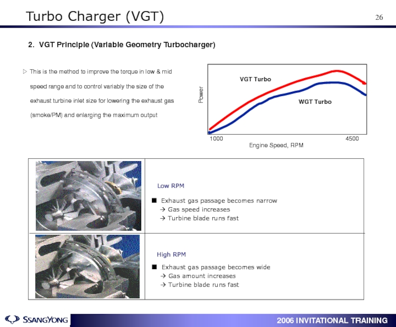
- Маркетинг
- Математика
- Медицина
- Менеджмент
- Музыка
- МХК
- Немецкий язык
- ОБЖ
- Обществознание
- Окружающий мир
- Педагогика
- Русский язык
- Технология
- Физика
- Философия
- Химия
- Шаблоны, картинки для презентаций
- Экология
- Экономика
- Юриспруденция
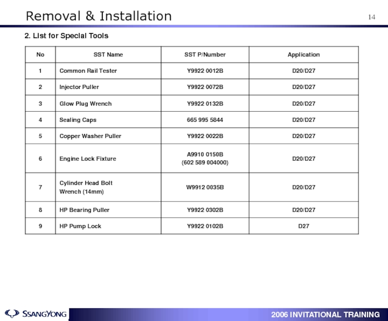
ACTYON Service Training. Engine : D20DT / D27DT. Engine General презентация
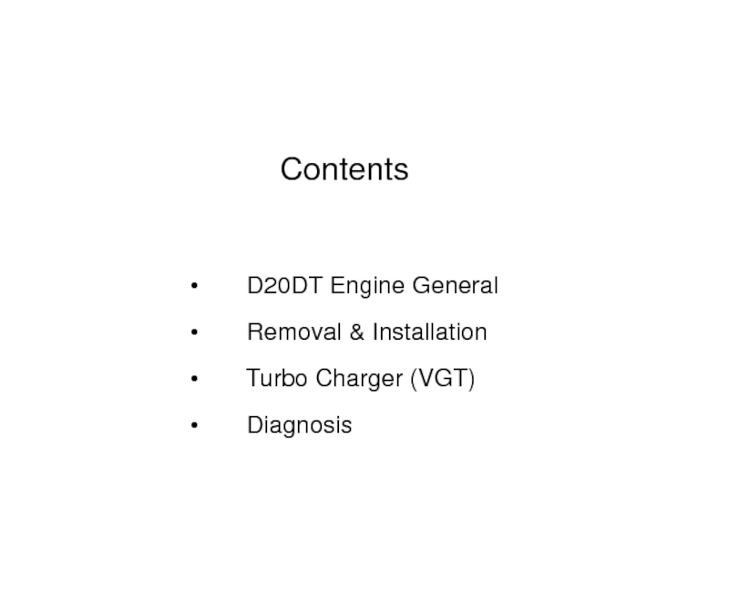
Содержание
- 1. ACTYON Service Training. Engine : D20DT / D27DT. Engine General
- 2. Contents
- 3. 1. Engine Room Description 1. Reservoir
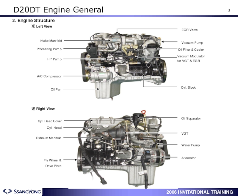
- 4. 2. Engine Structure D20DT Engine General
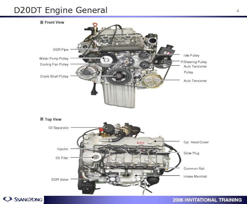
- 5. D20DT Engine General
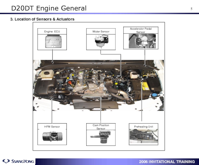
- 6. 3. Location of Sensors & Actuators D20DT Engine General
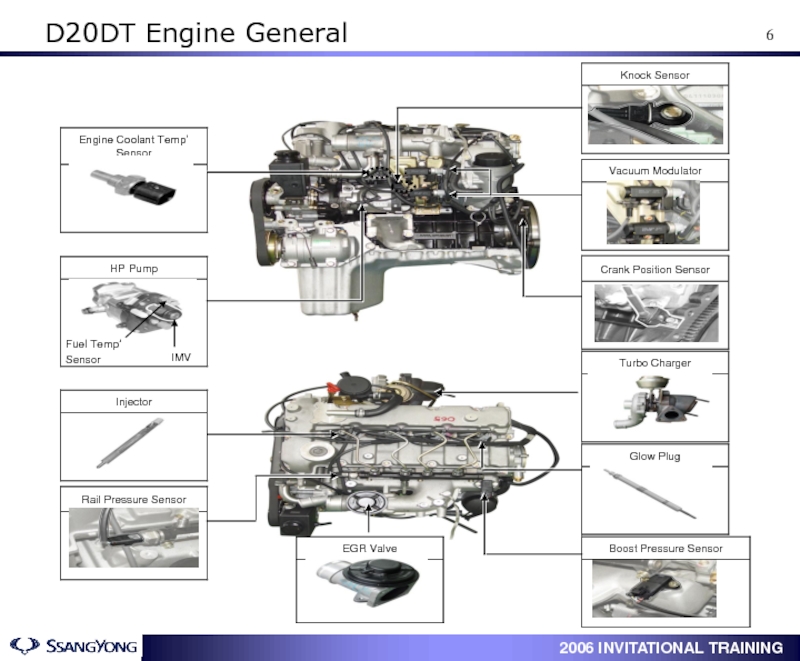
- 7. D20DT Engine General
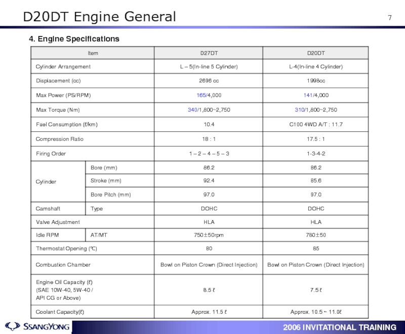
- 8. 4. Engine Specifications D20DT Engine General
- 9. 5. Engine Performance Curve 1) Horse
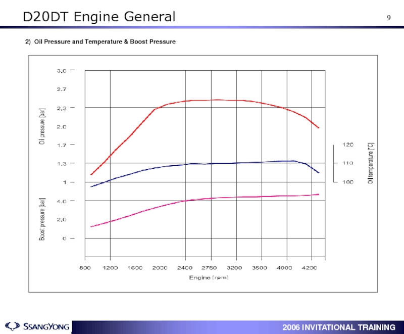
- 10. 2) Oil Pressure and Temperature & Boost Pressure D20DT Engine General
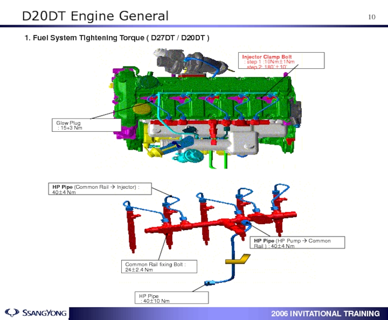
- 11. 1. Fuel System Tightening Torque ( D27DT
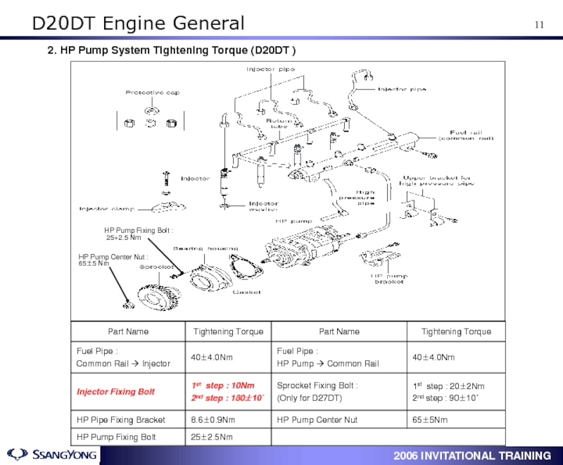
- 12. 2. HP Pump System Tightening Torque (D20DT ) D20DT Engine General
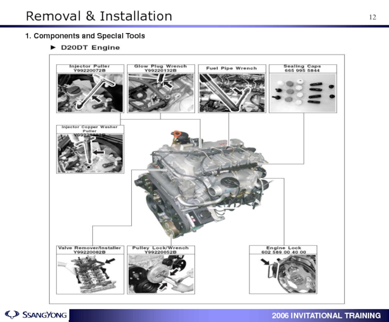
- 13. 1. Components and Special Tools Removal & Installation
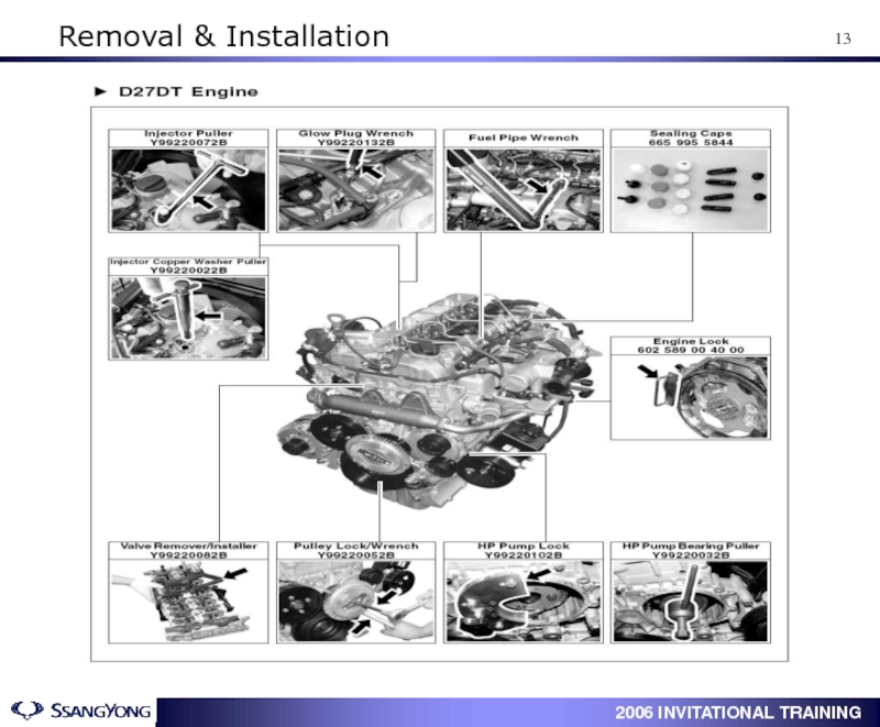
- 14. Removal & Installation
- 15. 2. List for Special Tools Removal & Installation
- 16. 1. Turn the auto tensioner counterclockwise
- 17. 5. Align the OT mark by rotating
- 18. 9. Slacken three HP pump mounting bolts
- 19. 2. Tighten the HP pump bolts.
- 20. 6. Install auto tensioner and belt pulley.
- 21. ① When installing/removing of chain or sprocket,
- 22. 4. Glow plug distinction When replacing one
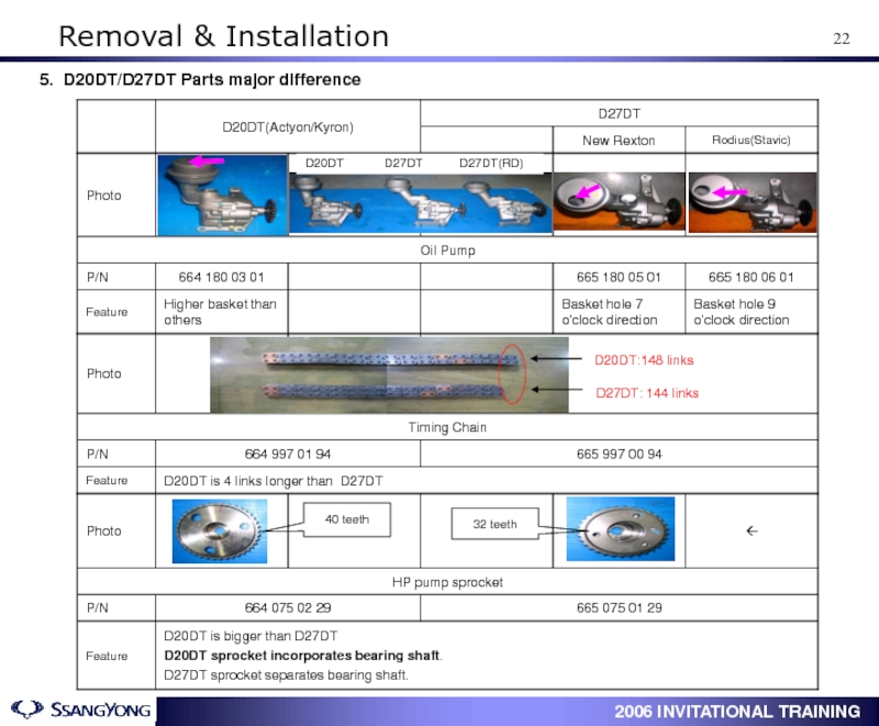
- 23. 5. D20DT/D27DT Parts major difference Removal & Installation
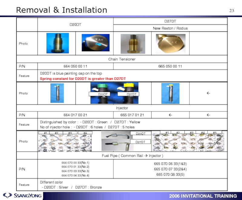
- 24. D20DT D27DT D20DT D27DT #1 #2 #3
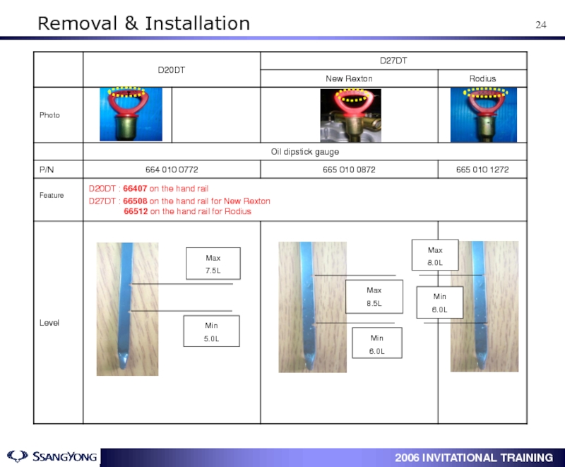
- 25. Max 7.5L Min 5.0L Max 8.5L Min
- 26. 1. Types of Turbo Charger Turbo Charger (VGT)
- 27. 2. VGT Principle (Variable Geometry Turbocharger) Engine
- 28. This represents that how much the ECU
- 29. Check if the VGT operates in normal
- 30. ① Be sure not to transmit external
- 31. ④ The screw for adjusting of actuator
- 32. 1. ECU Connector Diagnosis
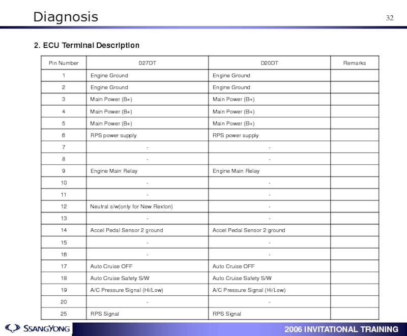
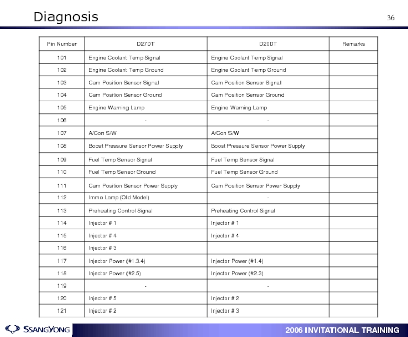
- 33. Diagnosis 2. ECU Terminal Description
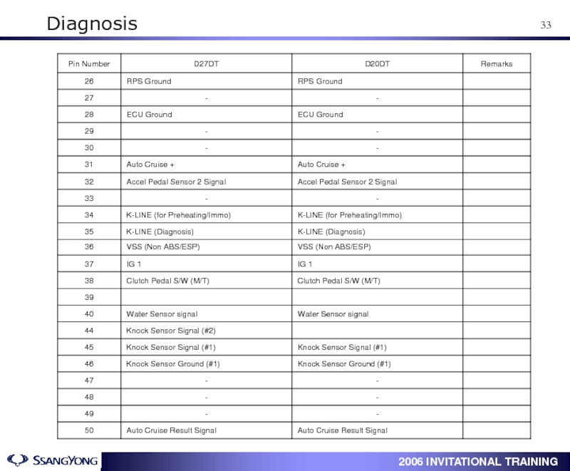
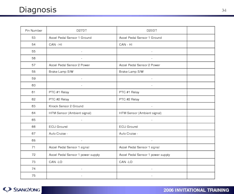
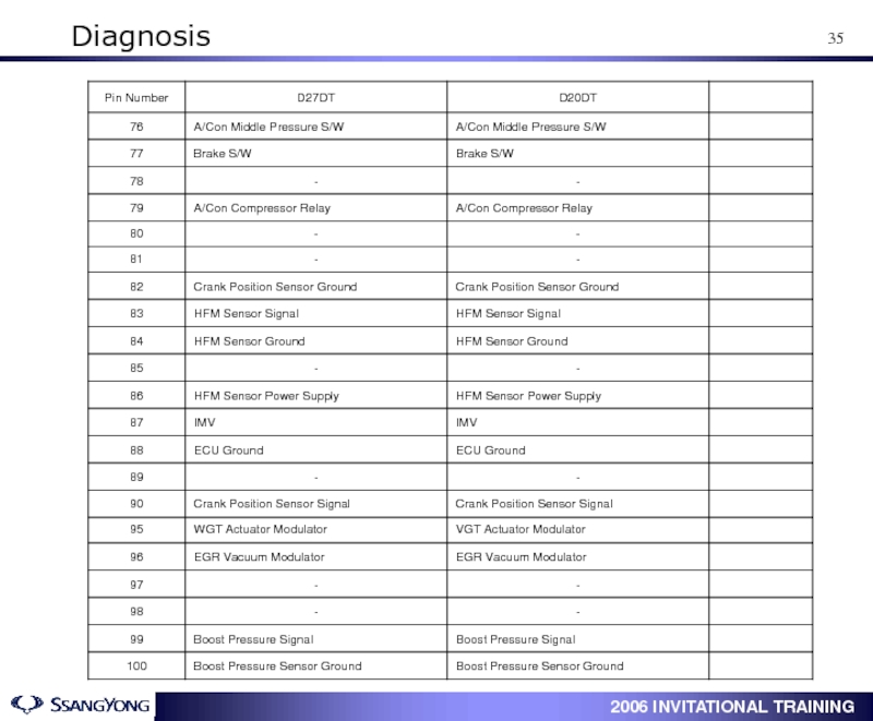
- 34. Diagnosis
- 35. Diagnosis
- 36. Diagnosis
- 37. Diagnosis
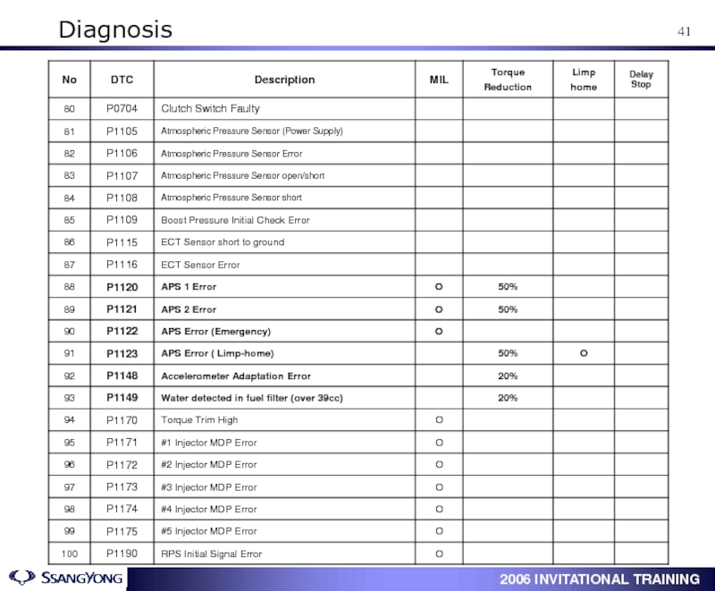
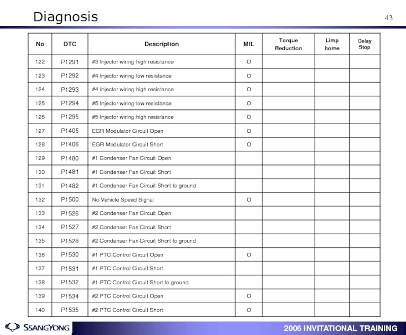
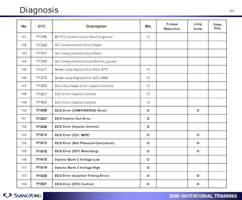
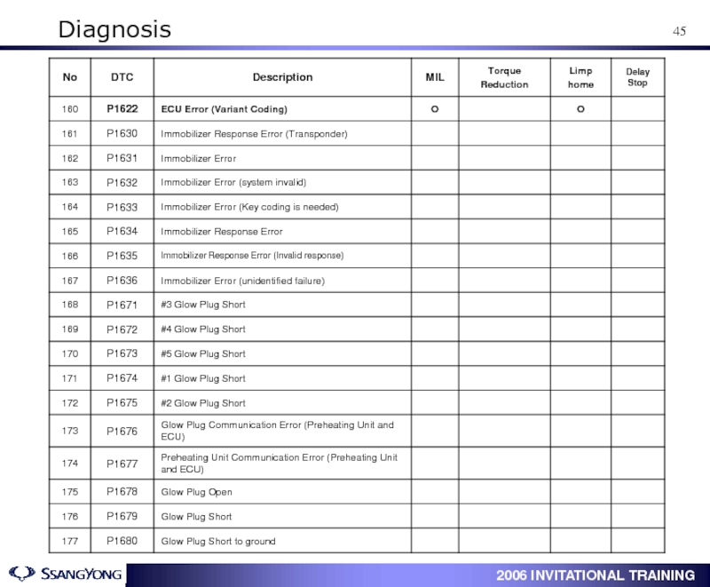
- 38. 2. Diagnostic Trouble Code Diagnosis
- 39. Diagnosis
- 40. Diagnosis
- 41. Diagnosis
- 42. Diagnosis
- 43. Diagnosis
- 44. Diagnosis
- 45. Diagnosis
- 46. Diagnosis
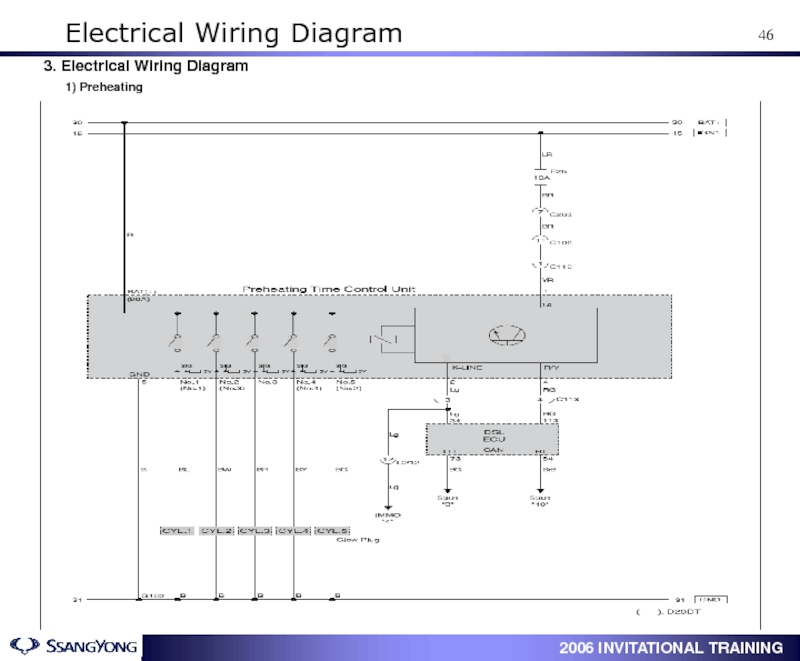
- 47. 3. Electrical Wiring Diagram 1) Preheating Electrical Wiring Diagram
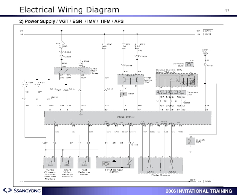
- 48. 2) Power Supply / VGT / EGR
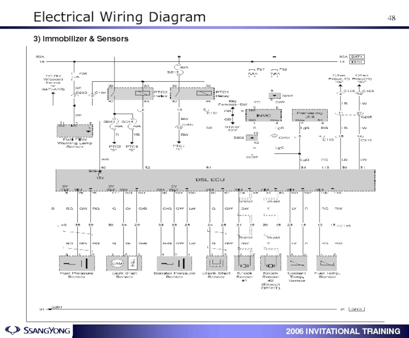
- 49. 3) Immobilizer & Sensors Electrical Wiring Diagram
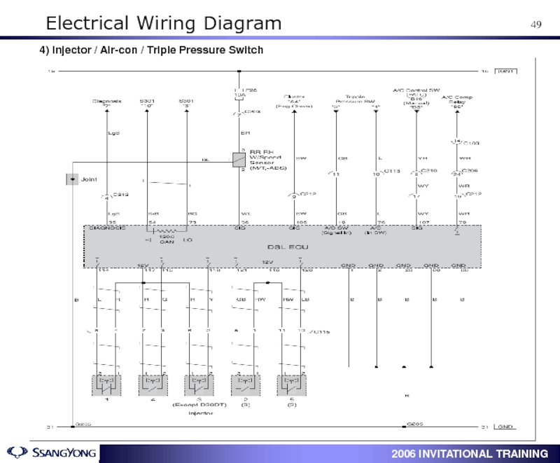
- 50. 4) Injector / Air-con / Triple Pressure Switch Electrical Wiring Diagram
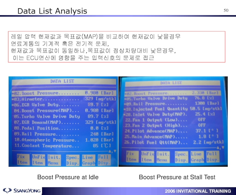
- 51. Data List Analysis Boost Pressure
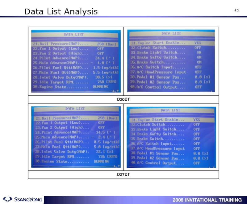
- 52. Data List Analysis
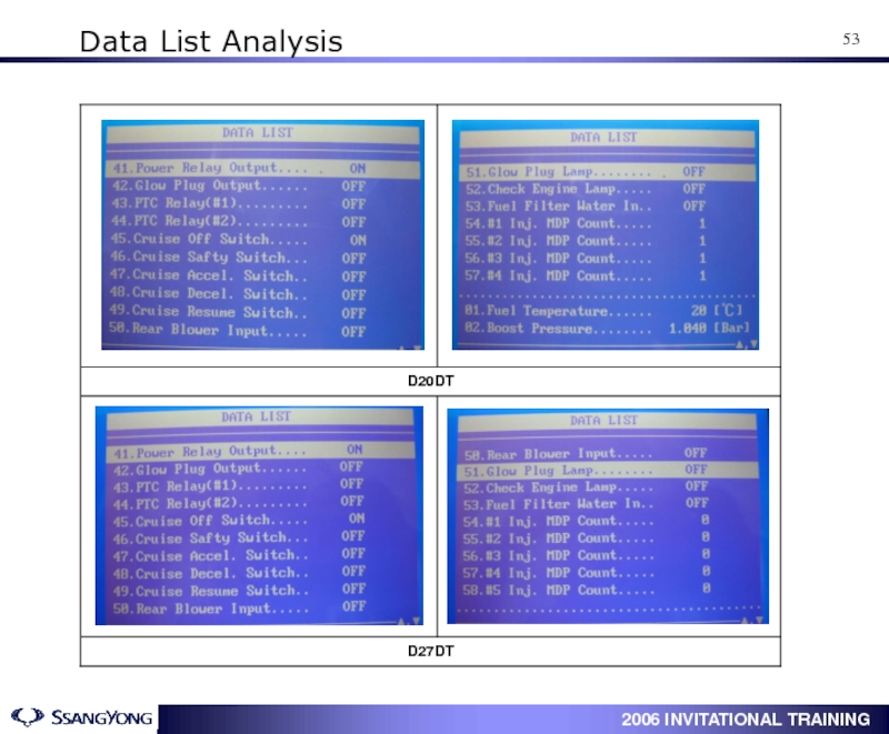
- 53. Data List Analysis
- 54. Data List Analysis
- 55. 1. Scan-100 Data List : Actyon(D20) /
- 56. Data List Analysis
- 57. Data List Analysis
- 58. Data List Analysis
- 59. Data List Analysis
Слайд 1ACTYON
Service Training
Engine : D20DT / D27DT
Subject :
Date : March .13 . 2006
Instructor : Brian Cho
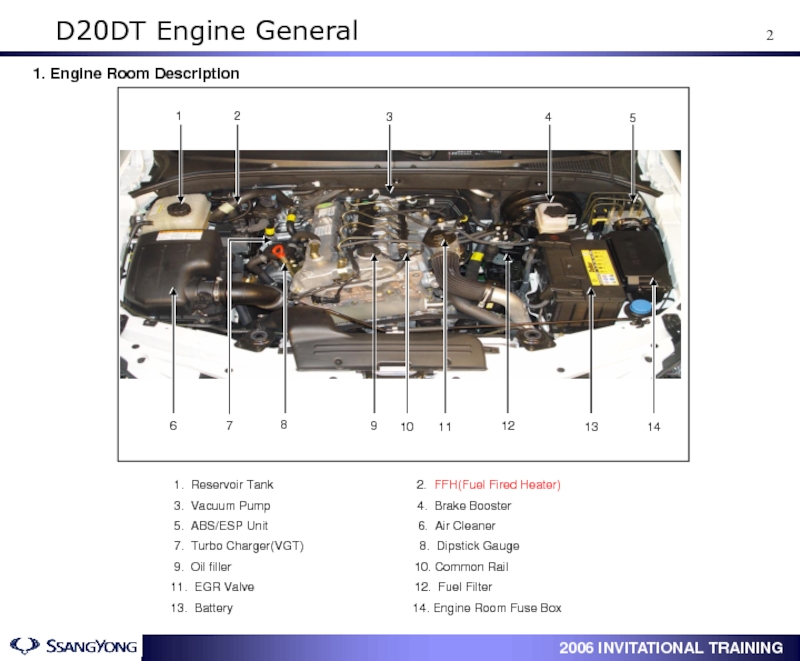
Слайд 31. Engine Room Description
1. Reservoir Tank
3. Vacuum Pump 4. Brake Booster
5. ABS/ESP Unit 6. Air Cleaner
7. Turbo Charger(VGT) 8. Dipstick Gauge
9. Oil filler 10. Common Rail
11. EGR Valve 12. Fuel Filter
13. Battery 14. Engine Room Fuse Box
D20DT Engine General
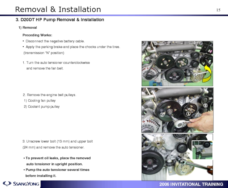
Слайд 161. Turn the auto tensioner counterclockwise
and remove the
2. Remove the engine belt pulleys.
1) Cooling fan pulley
2) Coolant pump pulley
Preceding Works:
▪ Disconnect the negative battery cable.
▪ Apply the parking brake and place the chocks under the tires.
(transmission “N” position)
3. Unscrew lower bolt (13 mm) and upper bolt
(24 mm) and remove the auto tensioner.
• To prevent oil leaks, place the removed
auto tensioner in upright position.
• Pump the auto tensioner several times
before installing it.
3. D20DT HP Pump Removal & Installation
1) Removal
①
③
②
Removal & Installation
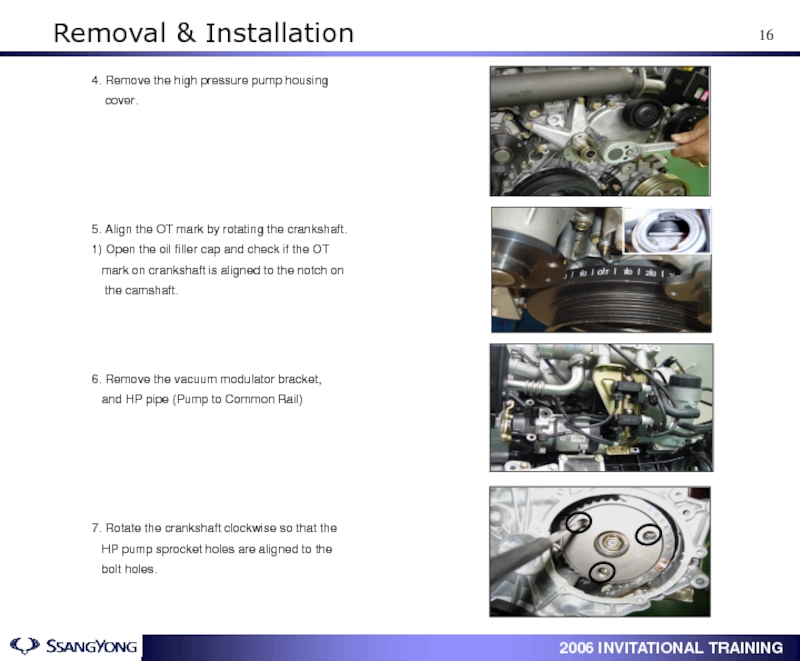
Слайд 175. Align the OT mark by rotating the crankshaft.
1) Open the
mark on crankshaft is aligned to the notch on
the camshaft.
6. Remove the vacuum modulator bracket,
and HP pipe (Pump to Common Rail)
4. Remove the high pressure pump housing
cover.
7. Rotate the crankshaft clockwise so that the
HP pump sprocket holes are aligned to the
bolt holes.
Removal & Installation
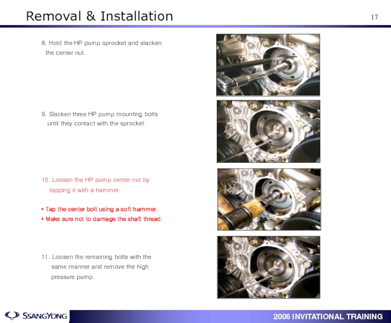
Слайд 189. Slacken three HP pump mounting bolts
until they
10. Loosen the HP pump center nut by
tapping it with a hammer.
• Tap the center bolt using a soft hammer.
• Make sure not to damage the shaft thread.
8. Hold the HP pump sprocket and slacken
the center nut.
11. Loosen the remaining bolts with the
same manner and remove the high
pressure pump.
Removal & Installation
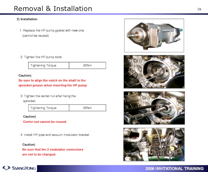
Слайд 192. Tighten the HP pump bolts.
3. Tighten the center nut after
sprocket.
1. Replace the HP pump gasket with new one.
(cannot be reused)
4. Install HP pipe and vacuum modulator bracket.
Caution)
Be sure that the 2 modulator connectors
are not to be changed.
2) Installation
Caution)
Center nut cannot be reused.
Caution)
Be sure to align the notch on the shaft to the
sprocket groove when inserting the HP pump
Removal & Installation
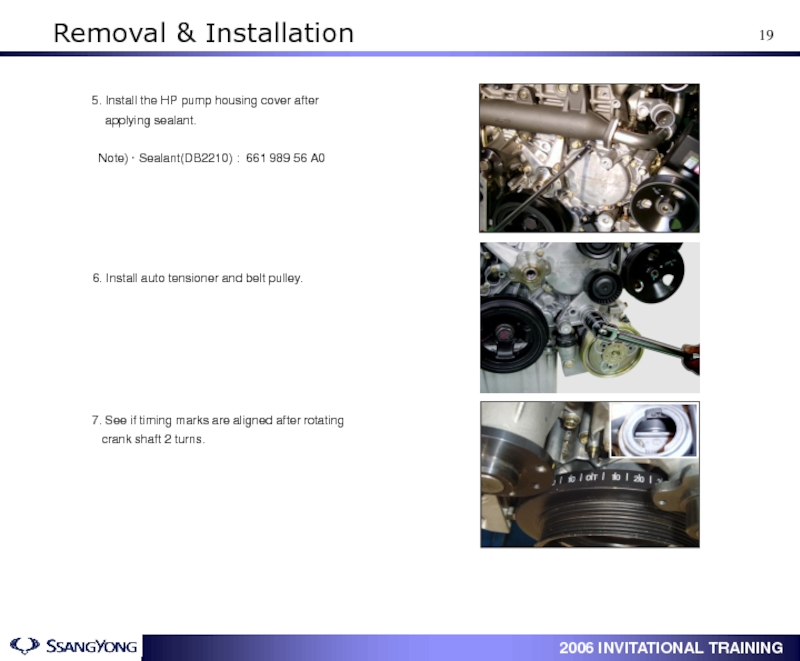
Слайд 206. Install auto tensioner and belt pulley.
7. See if timing marks
crank shaft 2 turns.
5. Install the HP pump housing cover after
applying sealant.
Note) · Sealant(DB2210) : 661 989 56 A0
Removal & Installation
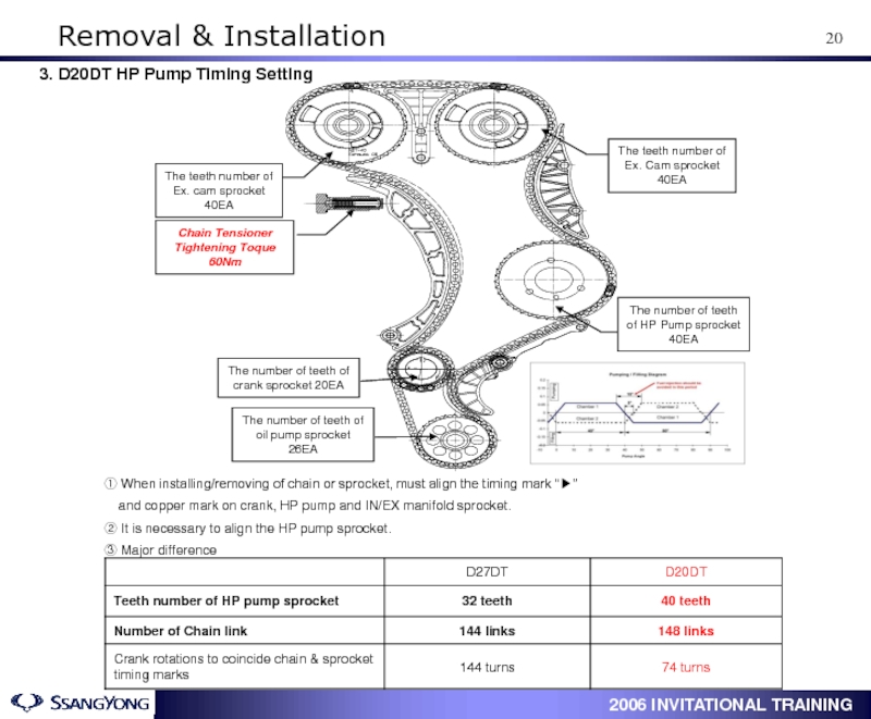
Слайд 21① When installing/removing of chain or sprocket, must align the timing
and copper mark on crank, HP pump and IN/EX manifold sprocket.
② It is necessary to align the HP pump sprocket.
③ Major difference
3. D20DT HP Pump Timing Setting
The teeth number of Ex. cam sprocket 40EA
The teeth number of Ex. Cam sprocket 40EA
Chain Tensioner Tightening Toque 60Nm
The number of teeth of HP Pump sprocket 40EA
The number of teeth of crank sprocket 20EA
The number of teeth of oil pump sprocket 26EA
Removal & Installation
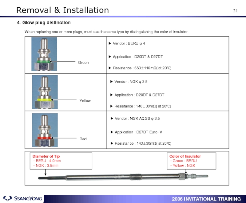
Слайд 224. Glow plug distinction
When replacing one or more plugs, must use
▶ Vendor : BERU φ 4
▶ Application : D20DT & D27DT
▶ Resistance : 680±110mΩ( at 20℃)
Green
Yellow
Red
Color of Insulator
- Green : BERU
- Yellow : NGK
Diameter of Tip
- BERU : 4.0mm
- NGK : 3.5mm
▶ Vendor : NGK φ 3.5
▶ Application : D20DT & D27DT
▶ Resistance : 140±30mΩ( at 20℃)
▶ Vendor : NGK AQGS φ 3.5
▶ Application : D27DT Euro-IV
▶ Resistance : 140±30mΩ( at 20℃)
Removal & Installation
Слайд 272. VGT Principle (Variable Geometry Turbocharger)
Engine Speed, RPM
1000
4500
VGT Turbo
WGT Turbo
Power
▷
speed range and to control variably the size of the
exhaust turbine inlet size for lowering the exhaust gas
(smoke/PM) and enlarging the maximum output
High RPM
■ Exhaust gas passage becomes narrow
Gas speed increases
Turbine blade runs fast
Low RPM
■ Exhaust gas passage becomes wide
Gas amount increases
Turbine blade runs fast
Turbo Charger (VGT)
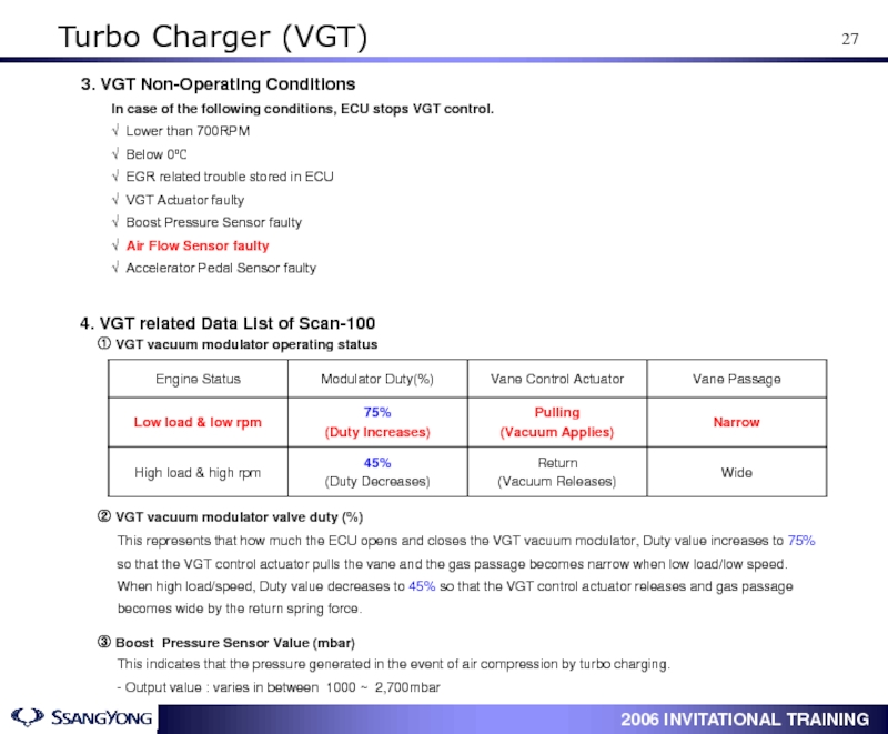
Слайд 28This represents that how much the ECU opens and closes the
3. VGT Non-Operating Conditions
4. VGT related Data List of Scan-100
① VGT vacuum modulator operating status
② VGT vacuum modulator valve duty (%)
This indicates that the pressure generated in the event of air compression by turbo charging.
- Output value : varies in between 1000 ~ 2,700mbar
③ Boost Pressure Sensor Value (mbar)
In case of the following conditions, ECU stops VGT control.
√ Lower than 700RPM
√ Below 0℃
√ EGR related trouble stored in ECU
√ VGT Actuator faulty
√ Boost Pressure Sensor faulty
√ Air Flow Sensor faulty
√ Accelerator Pedal Sensor faulty
Turbo Charger (VGT)
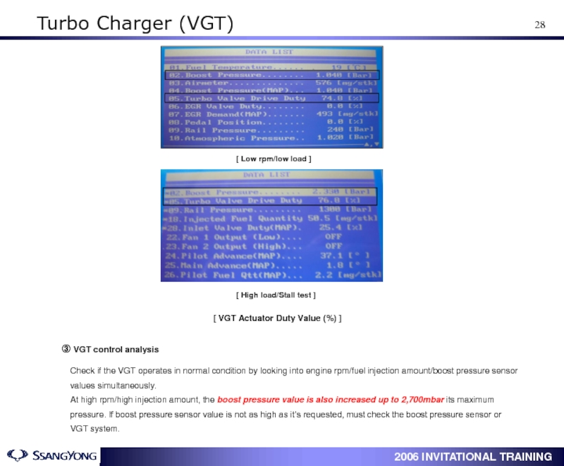
Слайд 29Check if the VGT operates in normal condition by looking into
At high rpm/high injection amount, the boost pressure value is also increased up to 2,700mbar its maximum pressure. If boost pressure sensor value is not as high as it’s requested, must check the boost pressure sensor or VGT system.
③ VGT control analysis
[ VGT Actuator Duty Value (%) ]
[ Low rpm/low load ]
[ High load/Stall test ]
Turbo Charger (VGT)
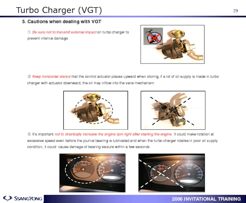
Слайд 30① Be sure not to transmit external impact on turbo charger
5. Cautions when dealing with VGT
② Keep horizontal stance that the control actuator places upward when storing, if a lot of oil supply is made in turbo charger with actuator downward, the oil may inflow into the vane mechanism.
③ It’s important not to drastically increase the engine rpm right after starting the engine. It could make rotation at excessive speed even before the journal bearing is lubricated and when the turbo charger rotates in poor oil supply condition, it could cause damage of bearing seizure within a few seconds.
Turbo Charger (VGT)
Слайд 31④ The screw for adjusting of actuator shaft should not be
⑤ Don’t grip the actuator shaft while transferring or removing.
⑥ Before installing a new VGT, fill a little of oil on the inlet pipe connecting hold.
⑦ Be sure not to be inserted any metallic matters when installing.
Turbo Charger (VGT)
Слайд 51 Data List Analysis
Boost Pressure at Stall Test
Boost Pressure
레일 압력 현재값과 목표값(MAP)을 비교하여 현재값이 낮을경우
연료계통의 기계적 혹은 전기적 문제,
현재값과 목표값이 동일하나,목표값이 정상차량대비 낮은경우,
이는 ECU연산에 영향을 주는 입력신호의 문제로 접근
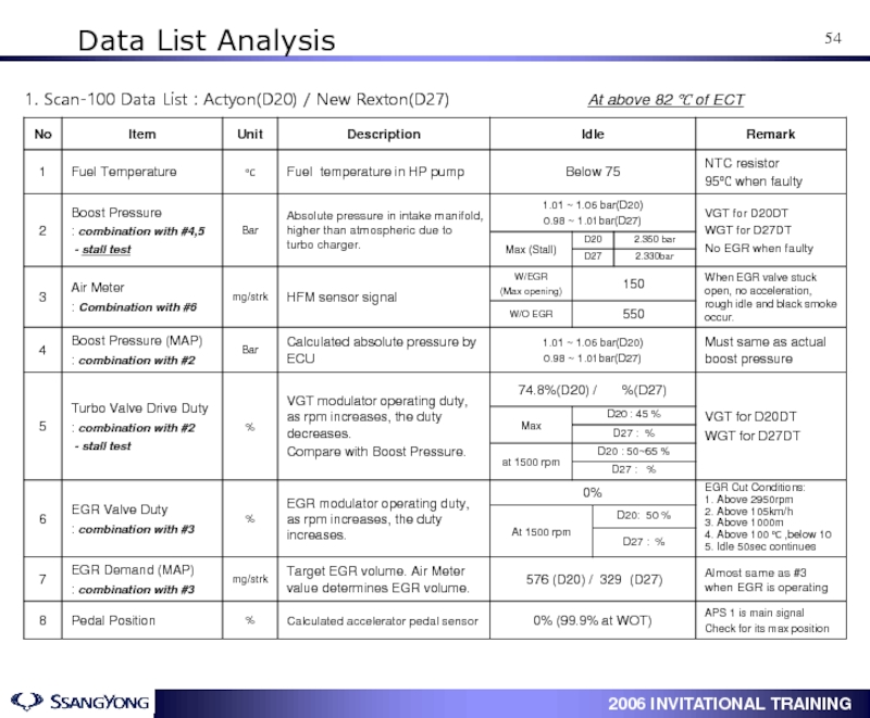
Слайд 551. Scan-100 Data List : Actyon(D20) / New Rexton(D27)
Data List Analysis
