- Главная
- Разное
- Дизайн
- Бизнес и предпринимательство
- Аналитика
- Образование
- Развлечения
- Красота и здоровье
- Финансы
- Государство
- Путешествия
- Спорт
- Недвижимость
- Армия
- Графика
- Культурология
- Еда и кулинария
- Лингвистика
- Английский язык
- Астрономия
- Алгебра
- Биология
- География
- Детские презентации
- Информатика
- История
- Литература
- Маркетинг
- Математика
- Медицина
- Менеджмент
- Музыка
- МХК
- Немецкий язык
- ОБЖ
- Обществознание
- Окружающий мир
- Педагогика
- Русский язык
- Технология
- Физика
- Философия
- Химия
- Шаблоны, картинки для презентаций
- Экология
- Экономика
- Юриспруденция
Medica Corporation EasyRA Service Training презентация
Содержание
- 1. Medica Corporation EasyRA Service Training
- 2. Reagents-Instructions for use Note:
- 6. The “Debug Mode” When Medica Technical Support
- 14. System Status
- 16. An error code appears-Now What ??? Reset
- 17. Investigate the Code – OM 11.2 A
- 18. Possible Values for Hardware Errors a =
- 19. Hardware Error Examples (OM sec 11.3)
- 20. System Error Codes
- 21. System Error Codes S0001-
- 22. System Error Codes
- 23. Let’s break that code down! P2304 P=Probe
- 24. Running Tests after a System Error System
- 25. Recovering Cancelled Tests If you end the
- 26. Legend of Results Flag codes To view
- 29. Measurement Problems They occur during the measurement
- 30. Measurement Problems- OM 11.11 Chemistries affected
- 31. Measurement Problems/Flags Appear in the Results Screen
- 32. Measurement Flags AS-
- 35. Measurement flag- SD (OM Table 11.2) Substrate
- 36. Range Errors User defined pre-set
- 38. Maintenance OM Section 10 Daily Weekly Monthly
- 39. Diagnostics EasyRA UI Service software (omit precision dye) ECData
- 40. Diagnostics in Reaction Area Transfer
- 41. Diagnostics – Reaction area Photometer test The
- 42. Diagnostics – Transfer Arm/Probe Arm Positioning
- 43. Diagnostics – Fluidics Drawer Dilutor Pump
- 44. Diagnostics – Reagent/Sample Area Sample Wheel
- 45. Precision
- 46. What if my precision test fails?? Check
- 47. EasyRA Best Practices Cals Controls Water Reagents Evaporation Environmental E-mail ECData
- 48. Service Training Special Tools Required and supplied by Medica
- 49. Alignment Cuvette Segment Photometer/Liquid level sense/temp cal
- 50. Wash Cup Alignment Tool
- 51. Sample Alignment Tool
- 52. Reagent Wedge Alignment Assembly
- 53. Digital Thermometer
- 54. Two Thermistors
- 55. Foam Insulation Ring
- 56. RFID Test Fixture/Wedge
- 57. Reagent Wedge Base Tool (shim)
- 58. Barcode Test Fixture
- 59. Adjustment Tool for Inductor
- 60. Digital Multimeter with Frequency Counter
- 61. Duct Tape
- 62. Service Software CD
- 63. Service
- 65. Fluidics Drawer / ISE’s ISE replacement
- 66. Dilutor Pump Replacement
- 67. Dilutor Pump Replacement
- 68. Dilutor Pump removal
- 70. Dilutor Pump removal
- 71. Dilutor Pump Replacement
- 72. Dilutor Pump Replacement
- 73. Peri Pump Replacement
- 74. Peri Pump Replacement ISE Module pg29
- 75. ISE Module Replacement
- 76. ISE Module Interface Cable Removal
- 77. ISE Fluidics Drawer
- 78. Sample Reagent Area Sample/Reagent Drive
- 79. Insulation Cap & Ring
- 80. Sample Reagent Drive Assembly
- 81. S/R Drive Assembly Removal Service Manual
- 82. RFID Reader replacement
- 83. Sample Reagent Area ISE
- 84. Removing the Mid Chassis & Parking Cover
- 85. Mid Chassis/Park Cover Removal
- 86. ISE Fan
- 87. Transfer Arm Assembly
- 88. After replacing the Transfer Arm Assembly you
- 89. Reaction Area – Service Manual Reaction
- 90. After Replacing the Fan and or Thermistor
- 91. Photometer Replacement
- 92. Photometer – Service Manual
- 93. Photometer – Service Manual
- 94. Check Voltages on PCB’s
- 95. Mother/Daughter PCB’s
Слайд 1Medica Corporation
EasyRA Service Training
Michael Holzapfel MT (ASCP)
EasyRA Application Specialist
EasyRA Application Specialist")
Слайд 2 Reagents-Instructions for use
Note: Check the inside of the
neck of the wedge for foam after removing the cap and placing the wedge on the analyzer. If there is foam, remove it with a swab or a disposable pipette before performing the test.

Слайд 3 Calcium
The calibration
interval (14 days maximum) is programmed on the RFID chip on the reagent wedge. Recalibration is required whenever there is a new wedge placed on the analyzer, a change in reagent lot number or if a shift in quality control values occurs.
 is programmed on the")
Слайд 4 CO2 & ALP
Keep the reagent tightly closed when not in use. When used in this way, the reagent is stable on-board in the refrigerated reagent area of the Medica EasyRA Chemistry Analyzer for the number of days programmed on the RFID chip on the reagent wedge.

Слайд 5 Total Protein
The reagent is
stable on-board in the refrigerated reagent area of the Medica EasyRA Chemistry Analyzer for the number of days programmed on the RFID chip on the reagent wedge if the reagent is recapped and removed at the end of the day and stored overnight at 18º-25oC. Do not use the reagent if it is turbid or cloudy or if it fails to recover known serum control values.

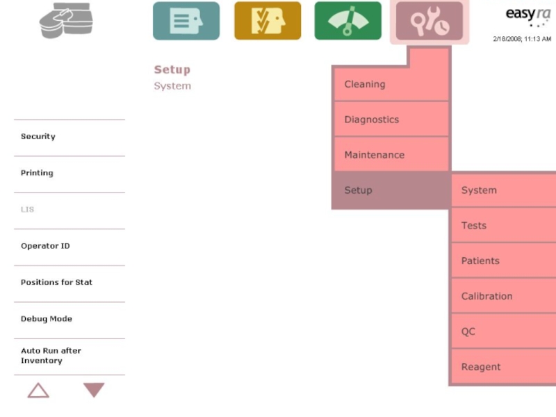
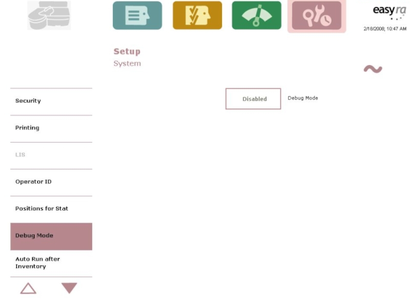
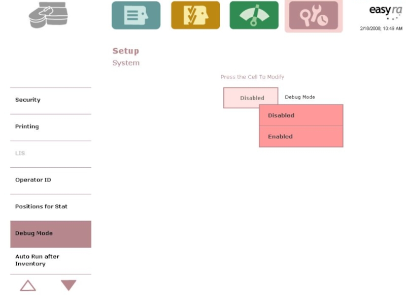
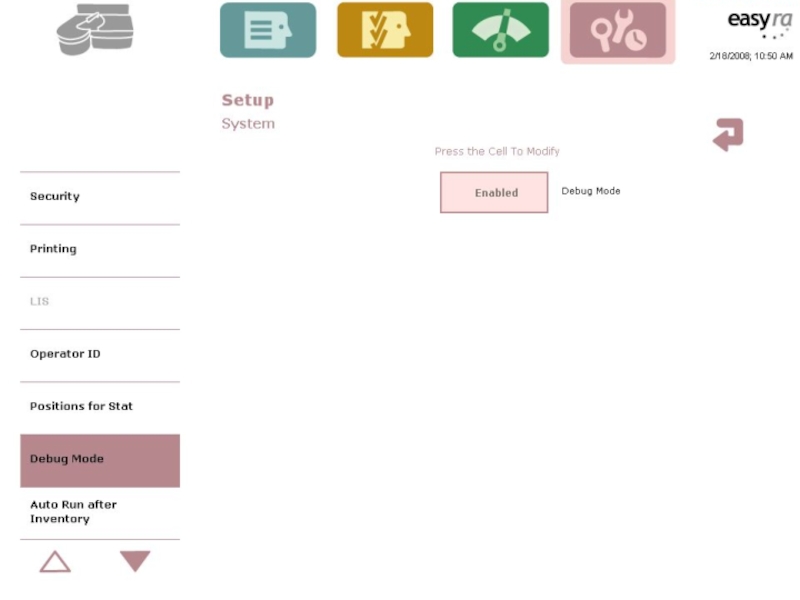
Слайд 6The “Debug Mode”
When Medica Technical Support says “Yes” or when additional
troubleshooting is required.
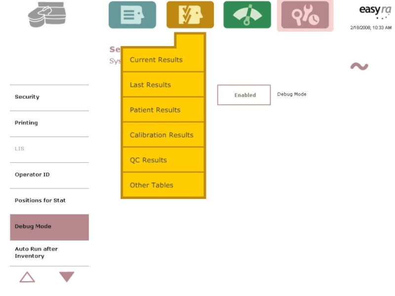
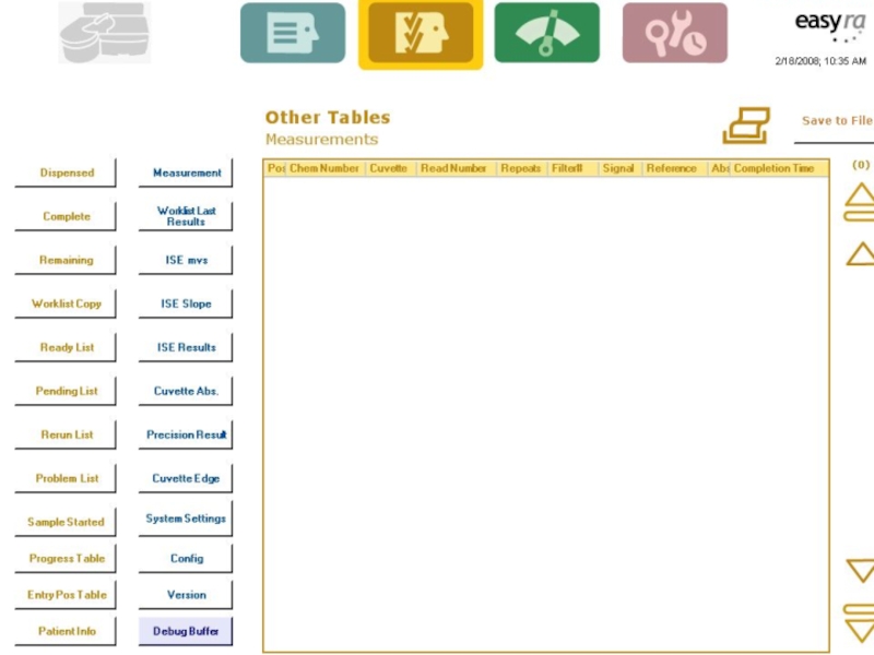
Additional info from the Results Menu
“Other Tables” (save to file/send to Medica)
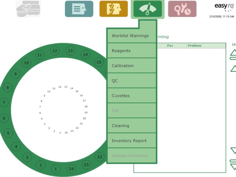
Additional info from the Status Menu
“Sample Inventory”
Additional info from the Results Menu
“Other Tables” (save to file/send to Medica)
Additional info from the Status Menu
“Sample Inventory”

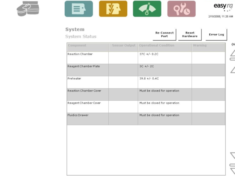
Слайд 14 System Status
Condition of key system components
Reaction
Chamber
Pre-Heater
Reaction Chamber Cover
Reagent Chamber Cover
Fluidics Drawer
Reconnect Port, Reset Hardware, Error Log
Pre-Heater
Reaction Chamber Cover
Reagent Chamber Cover
Fluidics Drawer
Reconnect Port, Reset Hardware, Error Log

Слайд 16An error code appears-Now What ???
Reset Hardware
Locate the subsystem in question
and perform Diagnostic test/s

Слайд 17Investigate the Code – OM 11.2
A five digit alphanumeric string having
the form axxyz
a - represents a subsystem/location or scheduler software where Easy RA detected the problem
xx –Represents the position on the Sample Ring/Reagent Tray or Cuvette Carousel
y&z- Further pinpoints the location and type of problem
a - represents a subsystem/location or scheduler software where Easy RA detected the problem
xx –Represents the position on the Sample Ring/Reagent Tray or Cuvette Carousel
y&z- Further pinpoints the location and type of problem

Слайд 18Possible Values for Hardware Errors
a = transfer arm
r = Reaction
Area/Cuvette Wheel
d = Dilutor Pump
p = Probe
d = Dilutor Pump
p = Probe
s = Sample/Reagent Wheel
f = Photometer
i = ISE module
t = Radio Frequency Tag
c = Communication Error

Слайд 19Hardware Error Examples (OM sec 11.3)
a0001- Transfer probe failure to
find home.
Check for object in path of Sample Probe
Other causes:
Optical Sensor Failure or Electro/Mechanical failure
To recover: Go to Diagnostic menu and select Transfer Arm/Probe/Arm positioning, Press Start.
Check for object in path of Sample Probe
Other causes:
Optical Sensor Failure or Electro/Mechanical failure
To recover: Go to Diagnostic menu and select Transfer Arm/Probe/Arm positioning, Press Start.
 a0001- Transfer probe failure to find home.Check for object")
Слайд 20 System Error Codes
P0124 – Empty Sample Cup
“ Check Sample at position 1”
ID0001- Turned off RA and the UI was running.
“Serial communication error”
“ Note: Make sure Easy RA is powered on and serial cable is connected. Press under to try again.
ID0001- Turned off RA and the UI was running.
“Serial communication error”
“ Note: Make sure Easy RA is powered on and serial cable is connected. Press

Слайд 21 System Error Codes
S0001- S0002 – Sample Wheel Home
and Position errors ( #1 home, #2 positioning)
P0214- Cap installed on the Reagent bottle (prompted to check position 2)
P0125 – No Cup in Sample Position
“No sample found. Check sample position 1.”
P0214- Cap installed on the Reagent bottle (prompted to check position 2)
P0125 – No Cup in Sample Position
“No sample found. Check sample position 1.”

Слайд 22 System Error Codes
P0124 – Empty Sample Cup
“ Check Sample at position 1”
ID0001- Turned off RA and the UI was running.
“Serial communication error”
“ Note: Make sure Easy RA is powered on and serial cable is connected. Press under to try again.
ID0001- Turned off RA and the UI was running.
“Serial communication error”
“ Note: Make sure Easy RA is powered on and serial cable is connected. Press

Слайд 23Let’s break that code down!
P2304
P=Probe
23=position#
0=R2, 1=R1, 2=Sample, 3=Wash,4=ISE, 5= test/cuvette
4= Bump
switch, 5= maximum steps

Слайд 24Running Tests after a System Error
System beeps to alert you of
the error
Window appears with the code
You may choose to end the run or continue measuring
Window appears with the code
You may choose to end the run or continue measuring

Слайд 25Recovering Cancelled Tests
If you end the run, all tests that are
in process are cancelled
Results are reported prior to the error
After accepting results, The Easy RA allows you to recover cancelled tests to a new work list!
Results are reported prior to the error
After accepting results, The Easy RA allows you to recover cancelled tests to a new work list!

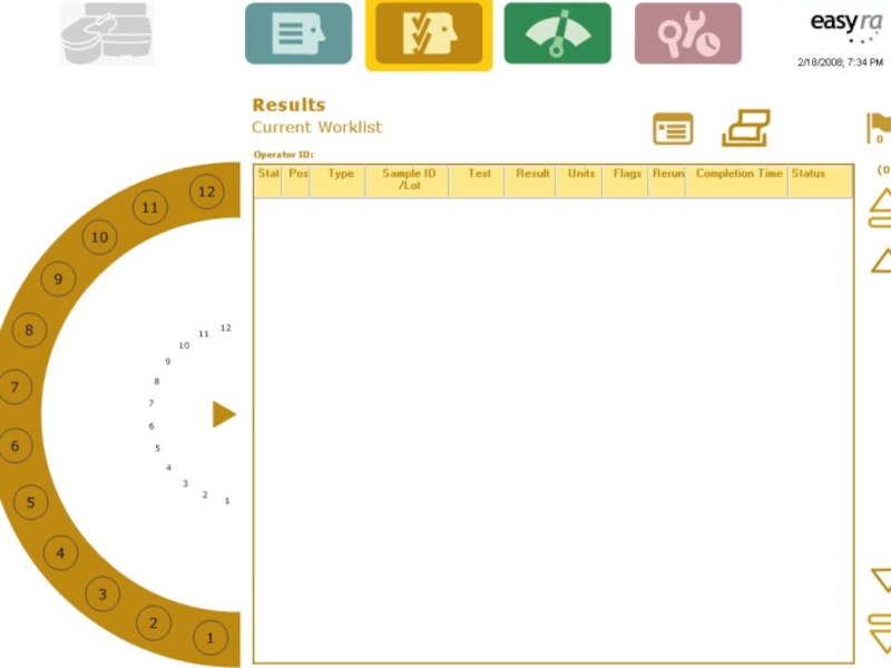
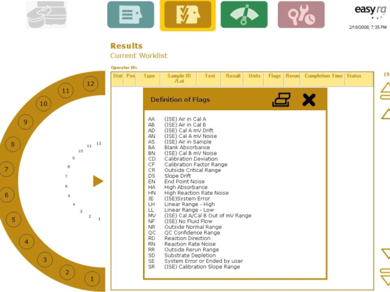
Слайд 26Legend of Results Flag codes
To view the legend touch the Flag
icon on the results screen.
25 possible codes which may appear in the Flag field on the Results screen if an abnormal condition is detected!
See sect 7.55 Operators manual.
25 possible codes which may appear in the Flag field on the Results screen if an abnormal condition is detected!
See sect 7.55 Operators manual.

Слайд 29Measurement Problems
They occur during the measurement phase of the test
The may
affect the resulted presented
In some cases results are suppressed because they will not represent and accurate assessment of the activity or concentration present.
In some cases results are suppressed because they will not represent and accurate assessment of the activity or concentration present.

Слайд 30Measurement Problems- OM 11.11
Chemistries affected
Abbreviation
Meaning
Troubleshooting & Recovery

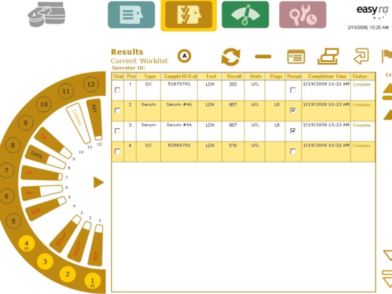
Слайд 31Measurement Problems/Flags
Appear in the Results Screen on the left side of
the Flags column ( with a range error)
OR they appear in the center of the Flags column
They can also appear on the ISE Calibration Results screen
OR they appear in the center of the Flags column
They can also appear on the ISE Calibration Results screen

Слайд 32 Measurement Flags
AS- Air in Sample (ISE”S)
Short Sample
Clot
in sample
CD- Calibrator Deviation
CV on triplicates > 5%
CF – Calibration Factor out of range
Factors found on Assay sheet or from RA
One chem/ all chems?
Calibrator/reagent.
CD- Calibrator Deviation
CV on triplicates > 5%
CF – Calibration Factor out of range
Factors found on Assay sheet or from RA
One chem/ all chems?
Calibrator/reagent.
Short SampleClot in sampleCD- Calibrator DeviationCV on triplicates")
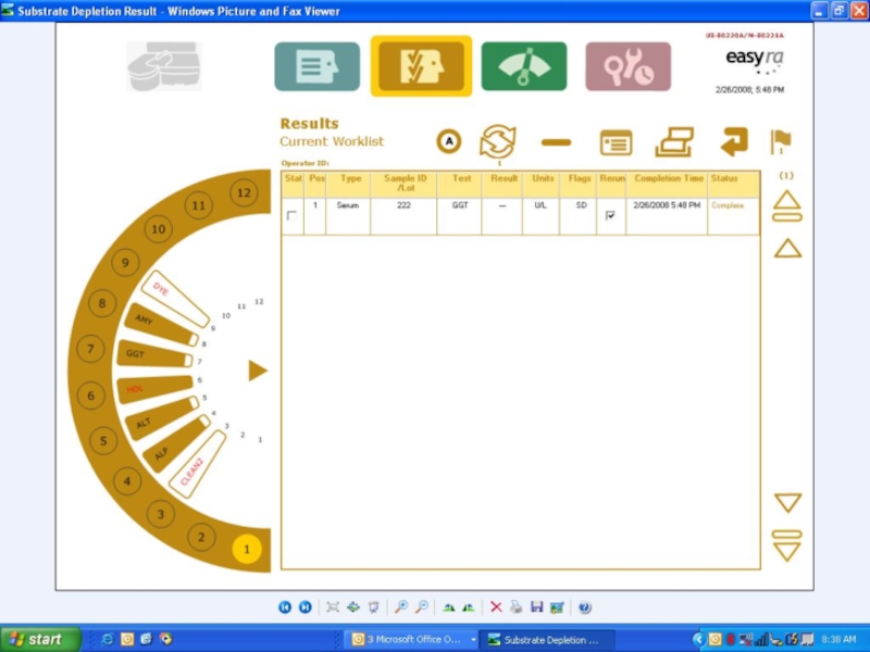
Слайд 35Measurement flag- SD (OM Table 11.2)
Substrate Depletion - Reagent ran out
of substrate for enzymes
To recover: Rerun the test. The Rerun program will
automatically reduce the sample volume to either 0.5 or 0.33 of the original sample volume and add to this same
Reagent volume. If the SD flag persists after auto dilution, dilute the sample with normal saline, and
then rerun the sample.
To recover: Rerun the test. The Rerun program will
automatically reduce the sample volume to either 0.5 or 0.33 of the original sample volume and add to this same
Reagent volume. If the SD flag persists after auto dilution, dilute the sample with normal saline, and
then rerun the sample.
Substrate Depletion - Reagent ran out of substrate for enzymes")
Слайд 36Range Errors
User defined pre-set ranges for:
QC Ranges - error code
= QC
Normal Ranges - error code = NR
Critical Ranges - error code = CR
Rerun Ranges – error code = RR
Normal Ranges - error code = NR
Critical Ranges - error code = CR
Rerun Ranges – error code = RR


 ECData")
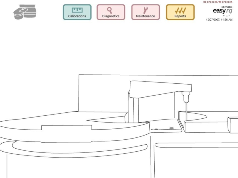
Слайд 40Diagnostics in
Reaction Area
Transfer Arm/Probe
Fluidics Drawer/ISE’s
Reagent Sample Area
Note: These diagnostic tests
are in the User Software
Heater Cooler
Cover/Door Latches
Precision Test

Слайд 41Diagnostics – Reaction area
Photometer test
The voltage output of the Read and
Reference photodiodes
The ratio of the Read and Reference diodes
The flash to flash precision (N=50) at each wavelength
Let’s run it now! OM pg 11.31
The ratio of the Read and Reference diodes
The flash to flash precision (N=50) at each wavelength
Let’s run it now! OM pg 11.31

Слайд 42Diagnostics – Transfer Arm/Probe
Arm Positioning
Probe positioning
Liquid Level Sensing
Let’s do it now!~
OM 11.36

Слайд 43Diagnostics – Fluidics Drawer
Dilutor Pump – dilutor pump error or precision
test failed/ QC “noisy”
Waste Pump- Not emptying properly/overflowing
ISE Sensor System-output of bubble detector with liquid and air, # of pump counts for all three pumps, output of sensors with CalA & B in front
Let’s do it Now! OM pg 11.46
Waste Pump- Not emptying properly/overflowing
ISE Sensor System-output of bubble detector with liquid and air, # of pump counts for all three pumps, output of sensors with CalA & B in front
Let’s do it Now! OM pg 11.46

Слайд 44Diagnostics – Reagent/Sample Area
Sample Wheel
Barcode Reader
RFID Reader
Let’s do it! OM pg
11.55

Слайд 45 Precision Test – OM 11.67
The
most important test on the
An indicator of the performance of the dilutor pump
Takes 12 minutes, 20 new cuvettes, and a precision dye wedge. Level 1= 16ul/180 and level 2=2ul and 255diluent.
Should always be performed weekly or when the sample probe, transfer arm, or photometer is replaced!
An indicator of the performance of the dilutor pump
Takes 12 minutes, 20 new cuvettes, and a precision dye wedge. Level 1= 16ul/180 and level 2=2ul and 255diluent.
Should always be performed weekly or when the sample probe, transfer arm, or photometer is replaced!

Слайд 46What if my precision test fails??
Check dilutor fittings on the right
side of the dilutor
Check for bubbles in the dilutor
Check/replace probe
Prime diluent and repeat test
Check for bubbles in the dilutor
Check/replace probe
Prime diluent and repeat test


")


Слайд 63 Service Software
Fluidics Drawer –
ISE’s
Sample/Reagent Area
Reaction Area
Photometer
Mother Board & Daughter Board
Sample/Reagent Area
Reaction Area
Photometer
Mother Board & Daughter Board

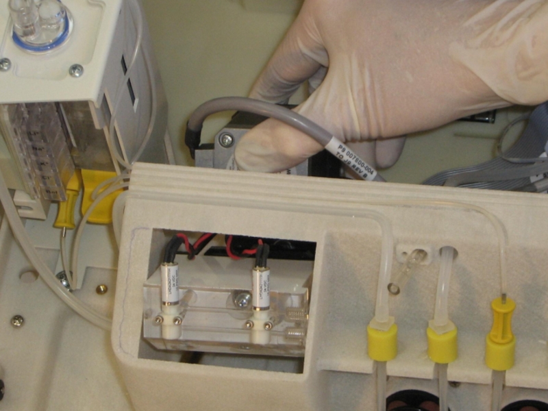
Слайд 65 Fluidics Drawer / ISE’s
ISE replacement - OM
Wash Cup replacement –
OM
ISE Module replacement
Dilutor Pump replacement
Peristaltic Pump replacement
ISE Module replacement
Dilutor Pump replacement
Peristaltic Pump replacement


Слайд 78 Sample Reagent Area
Sample/Reagent Drive Assembly
Fan Assembly (below coolers)
RFID Reader
ISE
Fan Assembly
Barcode Reader
Transfer Arm Assembly
Barcode Reader
Transfer Arm Assembly
RFID ReaderISE Fan AssemblyBarcode ReaderTransfer Arm Assembly")


Слайд 83 Sample Reagent Area
ISE Fan Assembly
Barcode Reader
Transfer Arm Assembly
NOTE! Remove
Mid chassis cover and Parking Cover to Replace the above assemblies. See Service manual!

Слайд 84Removing the Mid Chassis & Parking Cover allows you to…….
Remove/replace the
ISE fan assembly
Remove/replace the Barcode Reader assembly
Remove/replace the the Transfer arm assembly
Remove/replace the Barcode Reader assembly
Remove/replace the the Transfer arm assembly


Слайд 88After replacing the Transfer Arm Assembly you must…….
Perform an Alignment
Perform Liquid
Level Sense Calibration
Perform Liquid Level Sense Diagnostics
Perform a Z Axis Calibration
Perform a Pre-heater Calibration
Perform a Precision Dye Test
Let’s get started!
Perform Liquid Level Sense Diagnostics
Perform a Z Axis Calibration
Perform a Pre-heater Calibration
Perform a Precision Dye Test
Let’s get started!

Слайд 89 Reaction Area – Service Manual
Reaction Area Drive Assembly
Reaction Area Fan/Heater
Assembly
Reaction Area Thermistor
Reaction Area Thermistor

Слайд 90After Replacing the Fan and or Thermistor You must……
Perform a Temperature
calibration of the Reaction Area
Let’s get started!
Let’s get started!