- Главная
- Разное
- Дизайн
- Бизнес и предпринимательство
- Аналитика
- Образование
- Развлечения
- Красота и здоровье
- Финансы
- Государство
- Путешествия
- Спорт
- Недвижимость
- Армия
- Графика
- Культурология
- Еда и кулинария
- Лингвистика
- Английский язык
- Астрономия
- Алгебра
- Биология
- География
- Детские презентации
- Информатика
- История
- Литература
- Маркетинг
- Математика
- Медицина
- Менеджмент
- Музыка
- МХК
- Немецкий язык
- ОБЖ
- Обществознание
- Окружающий мир
- Педагогика
- Русский язык
- Технология
- Физика
- Философия
- Химия
- Шаблоны, картинки для презентаций
- Экология
- Экономика
- Юриспруденция
Survey & Design Workshop презентация
Содержание
- 1. Survey & Design Workshop
- 2. Contents
- 3. TSSR output procedure
- 4. TSSR output procedure
- 5. Contents
- 6. Product Description – ZTE (-48V ) DC
- 7. Product Description – ZTE (-48V ) DC
- 8. Product Description – BBU B8200
- 9. DCPD6 Dimensions:
- 10. DCPD7 1,DC input
- 11. Product Description – RRU (RRU types)
- 12. R8881 Product Description – RRU R8863
- 13. Product Description – RRU R8861 R8862A
- 14. Product Description – Micro BTS B8908 (2G)
- 15. Product Description – RRU RF cable RF
- 16. Product Description – RRU RF cable RF
- 17. Product Description – RRU RF cable RF
- 18. Product Description – RRU fiber cascading RRU
- 19. Different types of Fiber for different RRU
- 20. Site transmission Kiyvstar is responsed for upgrading the transmission to IP GE(E) .
- 21. AISG-U2100 R8861 RET Cell 1 Ant
- 22. AISG-U2100 R8863 RET Cell 1 Ant
- 23. Contents
- 24. Site overview
- 25. Site Scenarios-Site Equipment Principle
- 26. BBU and DCPD installation Scenario 1-In New/Existing
- 27. To be installed in New ZTE
- 28. 1 RRU fixing on pole kit-1 RRU
- 29. 2 RRU combined fixing on 1 pole
- 30. 3 RRU combined fixing on 1 pole
- 31. 4 RRU combined fixing on 1 pole
- 32. RRU installation General 3-on-1 pole and
- 33. To be installed at the backside
- 34. RRU installation components-Wall mount Wall mount fixing bracket kit---One RRU need 1 set bracket
- 35. RRU installation components-RRU gantry installation Indoor RRU
- 36. Tower Scenarios-Summary In case of Wrong RRU
- 37. Tower Scenarios
- 38. Tower Scenarios
- 39. Tower Scenarios Basic guidline for RRU
- 40. "H" support structure-For RRU installation Can be
- 41. “F" support structure-For RRU installation
- 42. Suggested RRU installation-Self support tower
- 43. Suggested RRU installation-Guyed master
- 44. Suggested RRU installation-Monopole
- 45. Suggested RRU installation- RT Pole(1 Single pole for all sector)
- 46. Suggested RRU installation-RT Pole(Separate pole for each sector)
- 47. Suggested RRU installation-RT Pole(Separate pole for each sector)
- 48. IBC sites solution scenario 1 Enough
- 49. IBC sites solution scenario 2(BS8908 Only can
- 50. Antenna Scenarios Basic guidline for Antennas
- 51. Antenna Scenarios Filters G900 Filters will be
- 52. Thank you


Слайд 6Product Description – ZTE (-48V ) DC system 2000mm rack
DC power
In case of only existing +24V DC power rack, no -48V DC power on site;
In case of cable tray height is more than 2000mm
ZTE -48V DC Power
ZXDUPA-FR01 Frame rack 2000mm
ZXDU68 B301(V5.0R01M01) DC power system
Rack Height:2000mm
Dimension of floor space:600mm*573mm
AC breaker requirement: 16A-TP
Floor space of ZXDUPA-FR01
 DC system 2000mm rackDC power solution scenarioIn case of")
Слайд 7Product Description – ZTE (-48V ) DC system 1600mm rack
DC power
In case of only existing +24V DC power rack, no -48V DC power on site;
In case of cable tray height is less than 2000mm
For PO1(132 sites) there is no 1.6m rack.
ZTE -48V DC Power
ZXDUPA-FR01 Frame rack 2000mm
ZXDU68 B301(V5.0R01M01) DC power system
Rack Height:1600mm
Dimension of floor space:600mm*573mm
AC breaker requirement: 16A-TP
Floor space of ZXDUPA-FR01
 DC system 1600mm rackDC power solution scenarioIn case of")

Слайд 9DCPD6
Dimensions: 43.6 (h) x 482.6 (w) x 228 (d)
(That means
Weight: 5.0kg
1,DC input interface
2,Switch for DC output for 9 paths(20A*9 paths)
3,Connector for DC output 9 paths
4,LP_ALM provides lighting protection alarm(Dry contact output)
DCPD6
Maximum (6 RRUs)+(1 BBU) to be connected to a single DCPD6.
Notes:
1,The 6 RRUs mentioned not include R8863, R8863 should not be connected to DCPD6 because of single R8863 got big power consumption.
2, 63A breaker in DC power system needed for DCPD6.
We can find site wise DCPD configuration in ZTE input data.
 x 482.6 (w) x 228 (d)(That means 1U space standard)Weight:")
Слайд 10DCPD7
1,DC input interface
2,Switch for DC output for 10 paths(25A*10 paths)
3,Connector for
4,LP_ALM provides lighting protection alarm(Dry contact output)
Dimensions: 43.6 (h) x 482.6 (w) x 228 (d)
(That means 1U space standard)
Weight: 5.0kg
DCPD7
Maximum (4 R8863)+(1 BBU) to be connected to a single DCPD7
Notes:
1, The R8863 only can be connected to DCPD7, not DCPD6.
2, Other RRUs also can be connected to DCPD7, as a sample, (3 R8863)+(2 other RRUs)+(1 BBU) or (2 R8863)+(3 other RRUs)+(1 BBU) . (The mentioned “other RRUs” include all types RRU except R8863.
3, 63A breaker in DC power system for DCPD7 needed.
We can find site wise DCPD configuration in ZTE input data.
3,Connector for DC output 10 paths4,LP_ALM")
Слайд 11Product Description – RRU (RRU types)
ODCPD1 needed for R886X if 2*10mm
R8863 will not be configured for RT Pole(Separate pole for each sector)
 ODCPD1 needed for R886X if 2*10mm DC cables used.R8863")


Слайд 14Product Description – Micro BTS B8908 (2G)
B8908
BS8908 only used
IBC site.
There is no space on site for (-48V DC rack+BBU+RRU) installation.
BS8908 only have 2G equipment in this period, that means for sites need to use BS8908,
3G can not be launched on this site.
B8908 BS8908 only used for sites which with following")
Слайд 15Product Description – RRU RF cable
RF G900 RRU (R8861 or R8881)
In
In case of G900 sector TRX >4, 2 RRUs need combination;
RF G900 RRU (R8863)
See blow RRU connection in case of 1 OR 2 R8863 for G900;
In case of G900 sector")
Слайд 16Product Description – RRU RF cable
RF D1800 RRU (R8862A)
See blow RRU
RF D1800 RRU (R8863)
See blow RRU connection in case of 2 OR 3 R8863 for D1800 all sectors;
(If any sector TRX of D1800>8,need 3 R8863,otherwise 2 R8863)
See blow RRU connection in case of")
Слайд 17Product Description – RRU RF cable
RF U2100 RRU (R8861)
See blow RRU
RF U2100 RRU (R8863)
See blow RRU connection in case of R8863 for U2100;
See blow RRU connection in case of")
Слайд 18Product Description – RRU fiber cascading
RRU fiber cascading
There are 6 optic
If RRUs <=6, all RRUs fiber connect to FS5 board optic ports directly.
If RRUs >6, 6 RRUs fiber connect to FS5 board optic ports directly, and for the other RRUs which more than 6, need fiber cascading connection.
Only can cascade internally in same system. That means we only can cascade G900 RRU to G900 RRU, D1800 RRU to D1800 RRU, U2100 RRU TO U2100 RRU. we can not cascade G900 RRU to D1800 RRU or U2100 RRU.
Maximum cascading 3 RRUs. (Not for R8863)
Fiber to BBU FS

Слайд 19Different types of Fiber for different RRU
The type of BBU-RRU fiber
Fiber for R888X:
There is a protection sleeve for fiber at the RRU side
Fiber for R886X:
There is no protection sleeve for fiber at the RRU side

 .")
Слайд 21AISG-U2100 R8861
RET
Cell 1 Ant
AISG
RET
Cell 2 Ant
AISG
RET
Cell 3 Ant
AISG
R8861 installed close to
AISG
AISG
AISG
AISG Only for UMTS

Слайд 22AISG-U2100 R8863
RET
Cell 1 Ant
AISG
RET
Cell 2 Ant
RET
Cell 3 Ant
R8863 installed close to
AISG
TX/RX
RX
TX/RX
RX
AISG cascading
AISG cascading
AISG Only for UMTS


Слайд 26BBU and DCPD installation
Scenario 1-In New/Existing 19” Rack
BBU&DCPD to be installed
BBU&DCPD to be installed on new 19’Rack(No existing BTS 19” rack or No enough space in existing 19’ rack)
Space requirement:
5U space for (BBU+1 DCPD)
7U space for (BBU+2 DCPD)
BBU to be installed on existing BTS 19’ rack or on new 19’ rack

Слайд 27
To be installed in New ZTE DC rack(Only for IBC sites)
The
In case of can not install new 19’ rack, just like some IBC sites due to space limited.
Space requirement:
5U space for (BBU+1 DCPD)
6U space for (BBU+2 DCPD)
BBU and DCPD installation
Scenario 2-In New ZTE DC Rack
The solution only used in")
Слайд 281 RRU fixing on pole kit-1 RRU need 1 set bracket
(Pole
RRU installation
Components-”1-on-1 pole”

Слайд 292 RRU combined fixing on 1 pole kit - 2 RRU
(Pole diameter requirement: 60mm to 120mm)
RRU installation
Components-”2-on-1 pole”

Слайд 303 RRU combined fixing on 1 pole kit - 3 RRU
(Pole diameter requirement: 60mm to 120mm)
RRU installation
Components-”3-on-1 pole”

Слайд 314 RRU combined fixing on 1 pole kit - 4 RRU
(Pole diameter requirement: 60mm to 120mm)
RRU installation
Components-”4-on-1 pole”

Слайд 32RRU installation
General
3-on-1 pole and 4-on-1 pole components are not available
RRU installation components can suit for below conditions(No need additional mount):
Pole diameter 60 –120 mm. If the diameter ≤ 90mm, use the pad on the bolt; otherwise, remove the pad.
The angle steel should range from 60 mm to 100 mm;
The channel steel should range from 63 mm to 100 mm.
Different RRU Installation solution for different RRUs:

Слайд 33
To be installed at the backside of antenna on the antenna
Space behind the antenna is more than 400mm
RRU installation
Scenario 1-1 Outdoor-At the backside of antenna
Scenario 1-2 Outdoor-At the backside of antenna

Слайд 34RRU installation components-Wall mount
Wall mount fixing bracket kit---One RRU need 1

Слайд 35RRU installation components-RRU gantry installation
Indoor RRU gantry
RRU installed on the Indoor
This is the second choice when the RRUs can not be installed on wall

Слайд 36Tower Scenarios-Summary
In case of Wrong RRU type configured in ZTE BOQ,
Modify all system RRUs during TSSR output, not only 3G;
For example, site survey shows rooftop guyed master on site, but in ZTE BOQ configure is not R8863, just send email to ZTE and get confirmation, change all RRU to R8863.


Слайд 39Tower Scenarios
Basic guidline for RRU installation
For masters:
U2100 R8863 to be
For guyed master and monopole, the R8863 for 900M and 1800M to be installed on the RRU pole or tower leg.
For SST, the RRUs to be installed on antenna pole or RRU pole or tower leg.
RT pole
RRUs to be installed on antenna pole or new RRU “F” pole according to site situation.

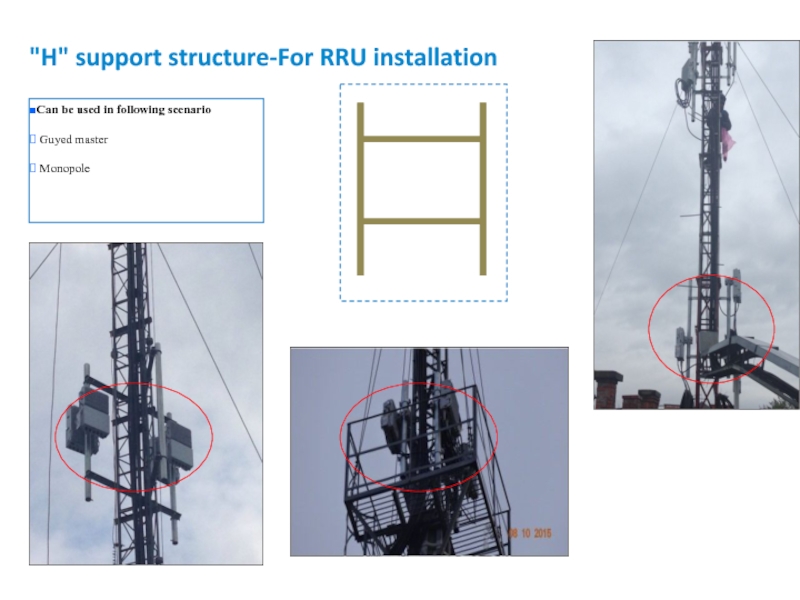
Слайд 40"H" support structure-For RRU installation
Can be used in following scenario
Guyed
Monopole


")
")
")
Слайд 48IBC sites solution scenario 1
Enough space for DC rack and RRU
-48V
2G+3G can be performed on site
Example

Слайд 49IBC sites solution scenario 2(BS8908 Only can launch 2G)
No space for
BS8908---AC 220V
Only 2G on be launched on site
Example
Example: Equipments only can be installed inside ceiling
No space for DC rack and RRUBS8908---AC")
Слайд 50Antenna Scenarios
Basic guidline for Antennas
We should check all sector ports
Plz pay special attention to D1800 ports requirement.
2G antenna should reuse existing antenna if possible.
3G antenna height
3G antenna height , azimuth and tilt based on 3G planning. If there is no planning for 3G, 3G antenna parameters follow 2G antenna.
If 3G planning height the same with 2G, and impossible to set antenna at the same level, the first priority of 3G antenna should be under 2G antenna within 3m distance. The second priority should be higher than 2G antenna within 3m distance.
3G antenna type and swap scenario
The first priority is to install new single band 3G 2 ports antenna if all condition is ok(Space on tower/RT pole is ok, Bearing capacity is ok) (Need consider new pole for 3G antenna)
If can not add separate antenna for 3G, following the guideline(BOQ and Antenna solution scenario_20160120_V3.0) based on scenarios.
If existing 4 ports (1710-2200M) antenna for D1800. After swap, if D1800 only use 2 ports, U2100 can reuse another 2 spare space and Kyivstar provide additional RCU module for this antenna). New RCU module quantity need to mark in report material list.

Слайд 51Antenna Scenarios
Filters
G900 Filters will be reused if existed on site.
Documents
305 sites
BOQ and Antenna solution scenario_20160120_V3.1