- Главная
- Разное
- Дизайн
- Бизнес и предпринимательство
- Аналитика
- Образование
- Развлечения
- Красота и здоровье
- Финансы
- Государство
- Путешествия
- Спорт
- Недвижимость
- Армия
- Графика
- Культурология
- Еда и кулинария
- Лингвистика
- Английский язык
- Астрономия
- Алгебра
- Биология
- География
- Детские презентации
- Информатика
- История
- Литература
- Маркетинг
- Математика
- Медицина
- Менеджмент
- Музыка
- МХК
- Немецкий язык
- ОБЖ
- Обществознание
- Окружающий мир
- Педагогика
- Русский язык
- Технология
- Физика
- Философия
- Химия
- Шаблоны, картинки для презентаций
- Экология
- Экономика
- Юриспруденция
Flight controls презентация
Содержание
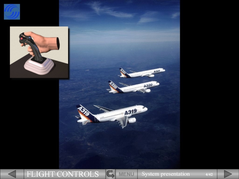
- 1. Flight controls
- 2. We will begin this module by explaining
- 3. This has the advantage of saving
- 6. The electrical signals created by sidestick
- 7. MENU This
- 10. PITCH TRIM
- 11. PITCH TRIM RUD
- 12. PITCH TRIM A rudder, RUD
- 13. PITCH TRIM RUD Now let’s
- 14. The movements of both ailerons and
- 15. The green rudder symbol is used
- 16. MENU
- 17. The PITCH TRIM position is indicated
- 18. MENU
- 19. MENU
- 20. MENU
- 21. On the ECAM F/CTL page, the
- 22. Two ELevator and Aileron Computers (ELAC),
- 23. In addition, two
- 24. However, the data
- 25. The status of ELAC and SEC
- 26. Three independent hydraulic systems are used
- 27. MENU
- 28. Pilots control pitch and roll through
- 29. There are associated side stick
- 30. Pitch trim wheels are located
- 31. MENU
- 32. A RUD TRIM panel is
- 33. A speed brake lever is
- 34. In addition, there are two
- 35. There are 5 slats on each
- 36. and 2 flaps on each trailing
- 37. The slats and flaps are hydraulically
- 38. Each SFCC has two channels, one
- 39. The flap lever, located on
- 40. The flaps and slats information is
- 41. This is Flap 0 indication. Notice
- 42. The slats and flaps are fitted
- 43. HYDRAULIC LIST OF SUBJECTS

Слайд 2We will begin this module by explaining the basic concept of
MENU
Fly by Wire

Слайд 3
This has the advantage of saving weight on the aircraft,
However, there
MENU
In conventional aircraft, the movement of the control column is transferred along cables and pulleys, until it reaches the control surface to be moved.
In the A320 family however, the cables and pulleys have been replaced by electrical wires.


Слайд 6
The electrical signals created by sidestick movement travel through flight control
These computers analyze the signal to check that it is a safe command and ensure the optimum flight control surface deflection for the demand.
MENU

Слайд 7
MENU
This has advantages over conventional systems. It :
makes the aircraft extremely
enhances safety,
reduces the workload of the pilot.
Let’s now look at the flight control surfaces themselves.


Слайд 12
PITCH TRIM
A rudder,
RUD
The flight control system incorporates:
Ailerons,
A Trimmable Horizontal Stabilizer (THS)
Elevators,
SPD BRK
Ground spoilers/Speed brakes.
MENU
 for pitch trim,Elevators,SPD BRKGround")
Слайд 13
PITCH TRIM
RUD
Now let’s introduce the ECAM F/CTL page.
You can see that
MENU

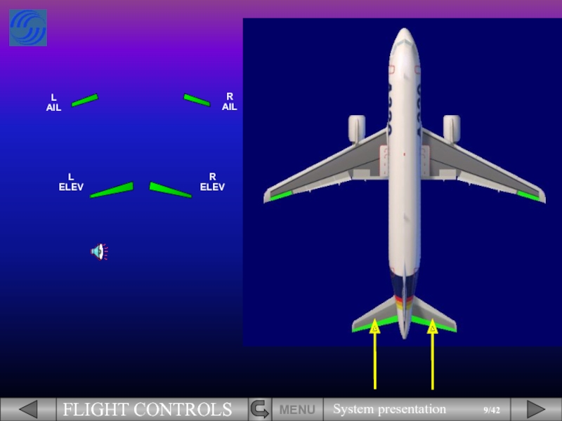
Слайд 14
The movements of both ailerons and both elevators are symbolized by
MENU

Слайд 15
The green rudder symbol is used as an index to display
The rudder trim is indicated by a small blue line below the scale.
MENU

Слайд 16
MENU
High speed position
Note that the rudder and the pedal deflections are
The high speed position is indicated by small white ticks on the rudder scale.

Слайд 17
The PITCH TRIM position is indicated by THS deflection in degrees
Let’s continue with the spoilers.
MENU


Слайд 19
MENU
Roll control uses the four outer surfaces,
On the video, look at
Click on the video window to start it !

Слайд 20MENU
Ground spoilers use all surfaces.
On the video, watch as all the
Click on the video window to start it !

Слайд 21
On the ECAM F/CTL page, the spoiler extended position is indicated
All these control surface indications will be explained in more detail in the normal and abnormal operation modules.
Now, we will look at the flight control computers.
MENU

Слайд 22
Two ELevator and Aileron Computers (ELAC),
Three Spoiler and Elevator Computers (SEC),
Two
The movements of the flight control surfaces are managed by seven computers. These are:
MENU
Flight control computers
,Three Spoiler and Elevator Computers (SEC),Two Flight Augmentation Computers (FAC).The")
Слайд 23
In addition, two Flight Control Data Concentrator computers (FCDC) are used
MENU
 are used to acquire data from")

Слайд 25
The status of ELAC and SEC is indicated on the ECAM
These indications will be seen in more detail in the abnormal operation module.
Now, we will see the hydraulic aspect.
MENU


Слайд 27
MENU
The hydraulic systems which actuate each control surface are indicated on
For example, the rudder is powered by the Green, Blue and Yellow hydraulic systems.
The ECAM F/CTL page is now complete.


Слайд 29
There are associated side stick priority lights.
Side sticks and priority lights
MENU


Слайд 34
In addition, there are two panels, located on the overhead panel
Now, we will introduce the lift augmentation devices.
MENU


Слайд 37
The slats and flaps are hydraulically actuated like all the other
MENU

Слайд 38
Each SFCC has two channels, one for the flaps and one
Each channel can drive its associated surfaces.
MENU

Слайд 39
The flap lever, located on the right side of the pedestal,
The flap lever has the following positions:
0, 1, 2, 3 and FULL.
MENU

Слайд 40
The flaps and slats information is shown on the E/WD.
The flap
MENU


Слайд 42
The slats and flaps are fitted with protection functions.
In particular, Surface
All these protections will be seen in detail in the abnormal operation modules.
MENU
NEXT
Module completed

Слайд 43
HYDRAULIC
LIST OF SUBJECTS
MENU
EXIT
GLOSSARY
AUDIO
FCOM
RETURN
FLIGHT BY WIRE
FLIGHT CONTROL SURFACES
COMPUTERS
CONTROLS
ECAM PAGES
SLATS and FLAPS