- Главная
- Разное
- Дизайн
- Бизнес и предпринимательство
- Аналитика
- Образование
- Развлечения
- Красота и здоровье
- Финансы
- Государство
- Путешествия
- Спорт
- Недвижимость
- Армия
- Графика
- Культурология
- Еда и кулинария
- Лингвистика
- Английский язык
- Астрономия
- Алгебра
- Биология
- География
- Детские презентации
- Информатика
- История
- Литература
- Маркетинг
- Математика
- Медицина
- Менеджмент
- Музыка
- МХК
- Немецкий язык
- ОБЖ
- Обществознание
- Окружающий мир
- Педагогика
- Русский язык
- Технология
- Физика
- Философия
- Химия
- Шаблоны, картинки для презентаций
- Экология
- Экономика
- Юриспруденция
Air-IQ software training презентация
Содержание
- 1. Air-IQ software training
- 2. Introductions Air-IQ Overview and Features Air-IQ AP
- 3. AIR-IQ OVERVIEW AND FEATURES
- 4. What is Air-IQ? Air-IQ is a collection
- 5. Web Browser AP TCP/IP Network AIR-IQ SOFTWARE
- 6. Supported WLAN ICs: BCM43460, BCM43520, BCM47452,
- 7. AIR-IQ LOCAL APPLICATION Display is integrated in
- 8. AIR-IQ RF MONITORING SERVICE AND CONSOLE Broadcom-based
- 9. RF MONITOR CONSOLE Provides visibility to the
- 10. AIR-IQ RF MONITOR SERVICE AND CONSOLE Air-IQ
- 11. AIR-IQ AP SOFTWARE STACK
- 12. AIR-IQ AP SOFTWARE STACK Two different architectures
- 13. AIR-IQ SERVICE ARCHITECTURE Air-IQ Service Architecture Air-IQ
- 14. AIR-IQ SERVICE ARCHITECTURE Air-IQ Service Architecture Air-IQ
- 15. AIR-IQ SERVICE ARCHITECTURE Air-IQ Service Architecture Air-IQ
- 16. AIR-IQ SERVICE ARCHITECTURE Air-IQ Service Architecture Air-IQ
- 17. Web Browser Local App UI AIR-IQ
- 18. AIR-IQ LIBRARY ARCHITECTURE WL Device Driver Air-IQ
- 19. BSA API OVERVIEW
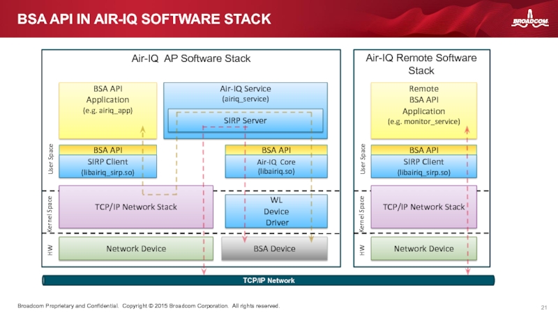
- 20. BSA = Broadcom Signal Analyzer Provides C-language
- 21. Air-IQ AP Software Stack BSA API Application
- 22. AIR-IQ SCAN MODES
- 23. Scanning is an essential part of Air-IQ.
- 24. An Air-IQ “Scan mode” is a loose
- 25. Air-IQ scans are requested by application software.
- 26. FFT interval is constrained by chip, ucode,
- 27. core_config – Selects which antenna/radio to use
- 28. For the most part, HW FFT functionality
- 29. Air-IQ uses the modesw module to switch
- 30. AIR-IQ SCANNING WITH PARAMETERS airiq_app command line
- 31. DEDICATED MODE – EXAMPLE 43460 Air-IQ scans
- 32. HYBRID MODE – EXAMPLE 43460 FFT duty
- 33. AIR-IQ SAMPLE APPLICATION CODE WALKTHROUGH
- 34. Demonstrates Air-IQ scanning using WL IOVAR interface
- 35. Airiq APP can be found in the
- 36. AIR-IQ AP SOFTWARE STACK INTEGRATION TASKS
- 37. Select Air-IQ Architecture (Service Architecture or Library
- 38. Install Air-IQ runtime files on AP file
- 39. Optional: Integrate Air-IQ Local App Adobe flash
- 40. How often do we get FFT, Interference
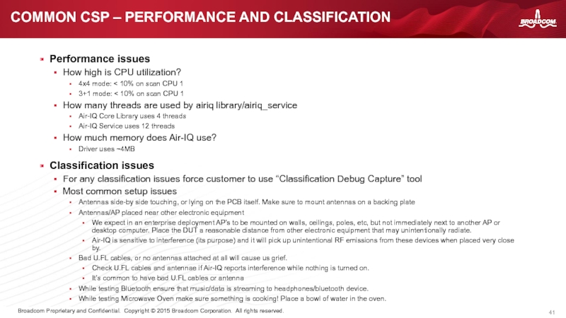
- 41. Performance issues How high is CPU utilization?
- 42. END
Слайд 2Introductions
Air-IQ Overview and Features
Air-IQ AP Software Stack
BSA API Overview
Air-IQ Scan Modes
Air-IQ
Air-IQ AP Software Stack Integration Tasks
Building Air-IQ Software Stack
Troubleshooting and Debug
Common CSP Issues
AGENDA
Слайд 4What is Air-IQ?
Air-IQ is a collection of software components for performing
Air-IQ AP Software Stack
Utilizes the FFT and IQ capture capabilities of Broadcom IEEE 802.11ac Wireless LAN ICs to capture FFT data and IQ data
Detects and classifies interference from 17 different types of non-WiFi devices
Calculates and reports non-WiFi channel utilization and channel quality
Provides Broadcom Signal Analyzer (BSA) API for accessing spectrum analysis data, events, and reports
Simple User interface for displaying interference events, channel quality, and non-WiFi channel utilization
Air-IQ RF Monitor Service
Provides centralized monitoring of up to 1500 Air-IQ enabled APs
Provides advanced spectrum analysis capabilities like:
Interference event clustering
Interference source localization
Spectral data recording/playback
Provides Broadcom Monitor Service (BMS) API for accessing all spectrum information for monitored APs
Air-IQ Monitor Console
User Interface for managing and displaying spectrum information collected by Monitor Service
Designed to be integrated into Web UI of WLAN controller and/or network management appliance.
WHAT IS AIR-IQ?
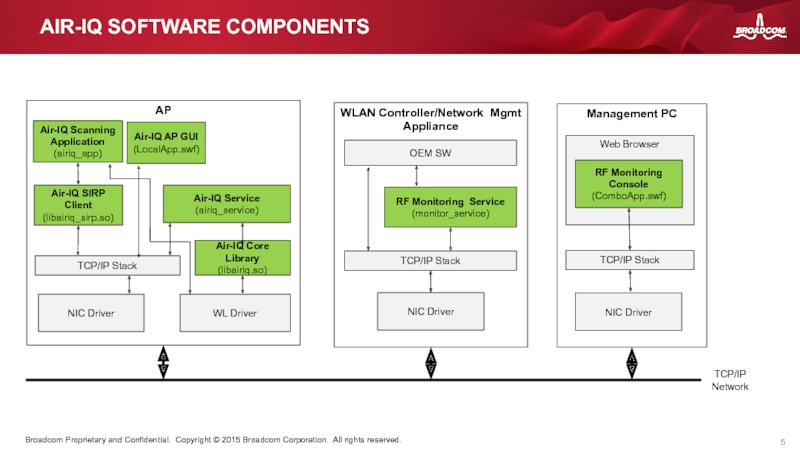
Слайд 5Web Browser
AP
TCP/IP Network
AIR-IQ SOFTWARE COMPONENTS
WLAN Controller/Network Mgmt Appliance
Air-IQ Service
(airiq_service)
NIC Driver
TCP/IP
Air-IQ Scanning Application (airiq_app)
WL Driver
Air-IQ AP GUI (LocalApp.swf)
RF Monitoring Service
(monitor_service)
TCP/IP Stack
NIC Driver
OEM SW
RF Monitoring Console
(ComboApp.swf)
Management PC
TCP/IP Stack
Air-IQ SIRP Client
(libairiq_sirp.so)
NIC Driver
Air-IQ Core Library
(libairiq.so)
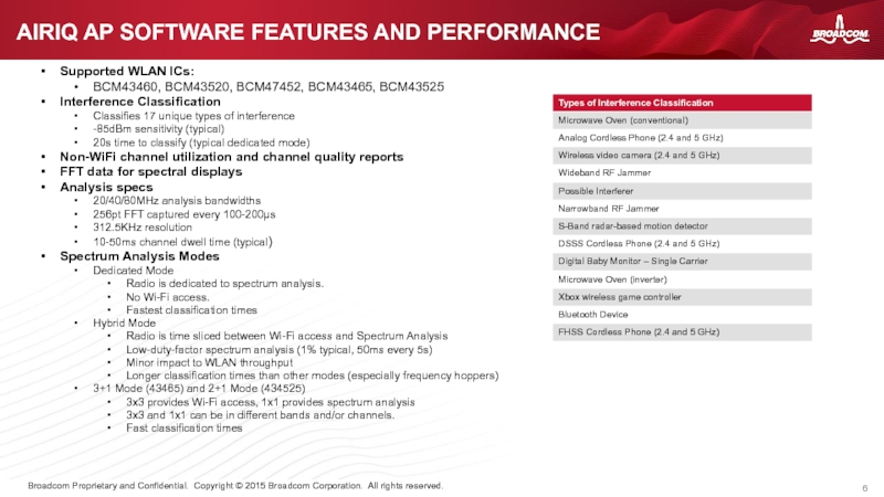
Слайд 6Supported WLAN ICs:
BCM43460, BCM43520, BCM47452, BCM43465, BCM43525
Interference Classification
Classifies 17 unique
-85dBm sensitivity (typical)
20s time to classify (typical dedicated mode)
Non-WiFi channel utilization and channel quality reports
FFT data for spectral displays
Analysis specs
20/40/80MHz analysis bandwidths
256pt FFT captured every 100-200µs
312.5KHz resolution
10-50ms channel dwell time (typical)
Spectrum Analysis Modes
Dedicated Mode
Radio is dedicated to spectrum analysis.
No Wi-Fi access.
Fastest classification times
Hybrid Mode
Radio is time sliced between Wi-Fi access and Spectrum Analysis
Low-duty-factor spectrum analysis (1% typical, 50ms every 5s)
Minor impact to WLAN throughput
Longer classification times than other modes (especially frequency hoppers)
3+1 Mode (43465) and 2+1 Mode (434525)
3x3 provides Wi-Fi access, 1x1 provides spectrum analysis
3x3 and 1x1 can be in different bands and/or channels.
Fast classification times
AIRIQ AP SOFTWARE FEATURES AND PERFORMANCE
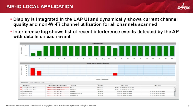
Слайд 7AIR-IQ LOCAL APPLICATION
Display is integrated in the UAP UI and dynamically
Interference log shows list of recent interference events detected by the AP with details on each event
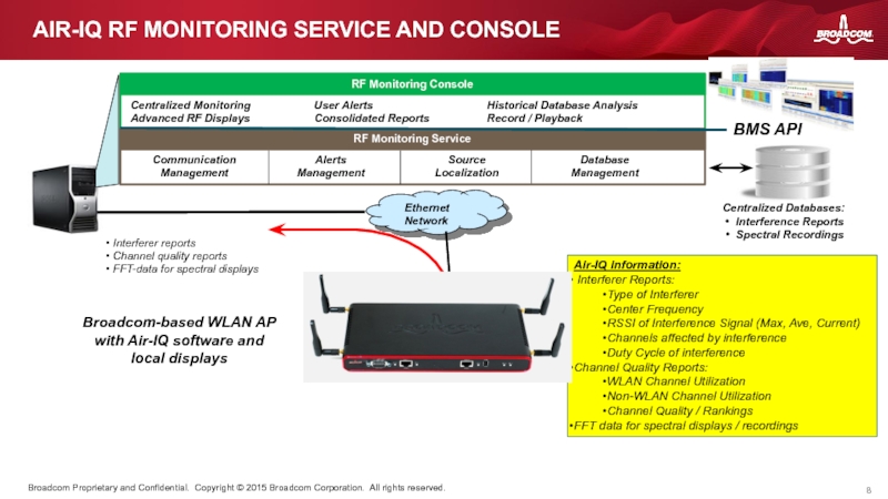
Слайд 8AIR-IQ RF MONITORING SERVICE AND CONSOLE
Broadcom-based WLAN AP
with Air-IQ software and
RF Monitoring Console
RF Monitoring Service
Centralized Databases:
Interference Reports
Spectral Recordings
Centralized Monitoring
Advanced RF Displays
User Alerts
Consolidated Reports
Historical Database Analysis
Record / Playback
Interferer reports
Channel quality reports
FFT-data for spectral displays
Air-IQ information:
Interferer Reports:
Type of Interferer
Center Frequency
RSSI of Interference Signal (Max, Ave, Current)
Channels affected by interference
Duty Cycle of interference
Channel Quality Reports:
WLAN Channel Utilization
Non-WLAN Channel Utilization
Channel Quality / Rankings
FFT data for spectral displays / recordings
BMS API
Communication
Management
Alerts
Management
Database
Management
Source
Localization
Слайд 9RF MONITOR CONSOLE
Provides visibility to the data collected and managed by
Provides remote and centralized configurability of APs for scheduled and alert-triggered spectral recordings
Displays include:
Statistics Dashboard Display
Interference and Event Log
Recording Log
Channel Quality Display
Channel Utilization Display
Channel Utilization vs. Time Display
Scrolling Spectrogram with interference classification overlays
Spectrum Analyzer Display
Persistence Display
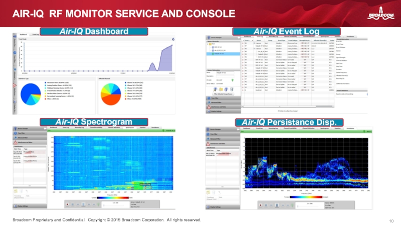
Слайд 10AIR-IQ RF MONITOR SERVICE AND CONSOLE
Air-IQ Dashboard
Air-IQ Spectrogram
Air-IQ Persistance Disp.
Air-IQ Event
Слайд 12AIR-IQ AP SOFTWARE STACK
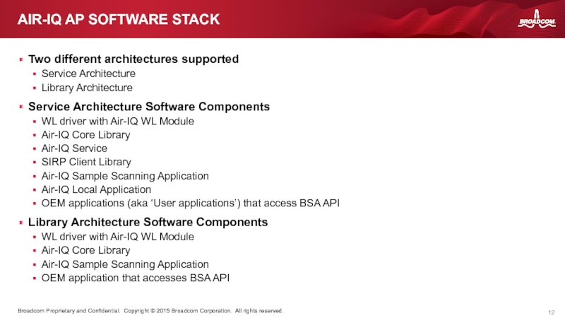
Two different architectures supported
Service Architecture
Library Architecture
Service Architecture Software
WL driver with Air-IQ WL Module
Air-IQ Core Library
Air-IQ Service
SIRP Client Library
Air-IQ Sample Scanning Application
Air-IQ Local Application
OEM applications (aka ‘User applications’) that access BSA API
Library Architecture Software Components
WL driver with Air-IQ WL Module
Air-IQ Core Library
Air-IQ Sample Scanning Application
OEM application that accesses BSA API
Слайд 13AIR-IQ SERVICE ARCHITECTURE
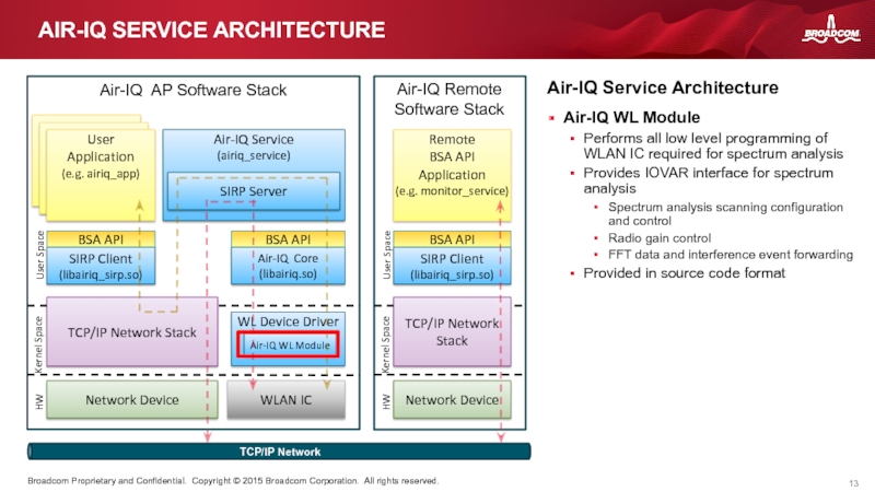
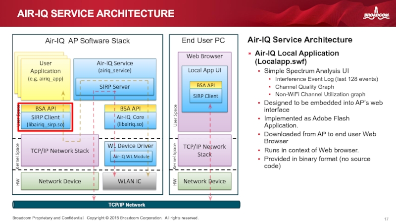
Air-IQ Service Architecture
Air-IQ WL Module
Performs all low level programming
Provides IOVAR interface for spectrum analysis
Spectrum analysis scanning configuration and control
Radio gain control
FFT data and interference event forwarding
Provided in source code format
Слайд 14AIR-IQ SERVICE ARCHITECTURE
Air-IQ Service Architecture
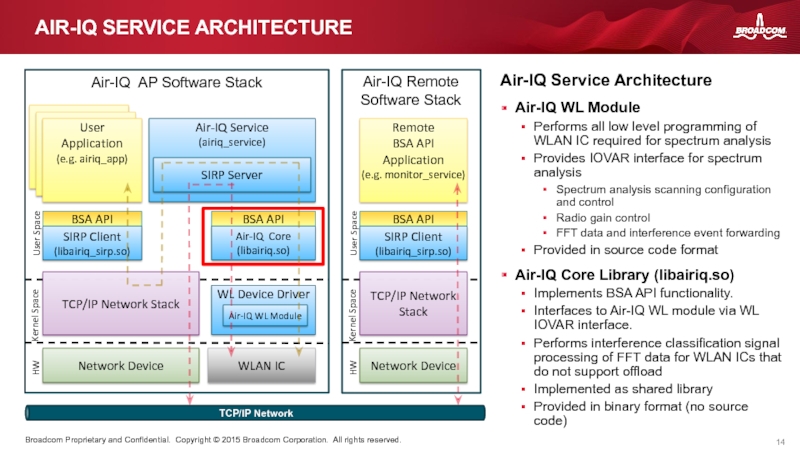
Air-IQ WL Module
Performs all low level programming
Provides IOVAR interface for spectrum analysis
Spectrum analysis scanning configuration and control
Radio gain control
FFT data and interference event forwarding
Provided in source code format
Air-IQ Core Library (libairiq.so)
Implements BSA API functionality.
Interfaces to Air-IQ WL module via WL IOVAR interface.
Performs interference classification signal processing of FFT data for WLAN ICs that do not support offload
Implemented as shared library
Provided in binary format (no source code)
Слайд 15AIR-IQ SERVICE ARCHITECTURE
Air-IQ Service Architecture
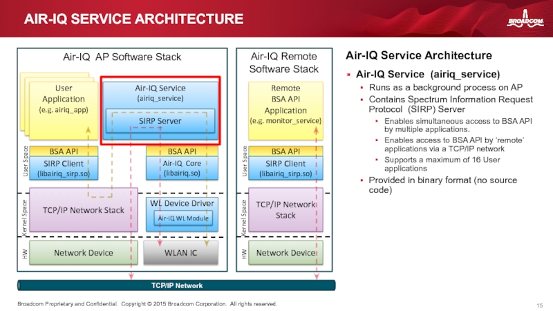
Air-IQ Service (airiq_service)
Runs as a background process
Contains Spectrum Information Request Protocol (SIRP) Server
Enables simultaneous access to BSA API by multiple applications.
Enables access to BSA API by ‘remote’ applications via a TCP/IP network
Supports a maximum of 16 User applications
Provided in binary format (no source code)
Слайд 16AIR-IQ SERVICE ARCHITECTURE
Air-IQ Service Architecture
Air-IQ Service (airiq_service)
Runs as a background process
Contains Spectrum Information Request Protocol (SIRP) Server
Enables simultaneous access to BSA API by multiple applications.
SIRP supports a maximum of User applications
Enables access to BSA API by ‘remote’ applications via a TCP/IP network
Provided in binary format (no source code)
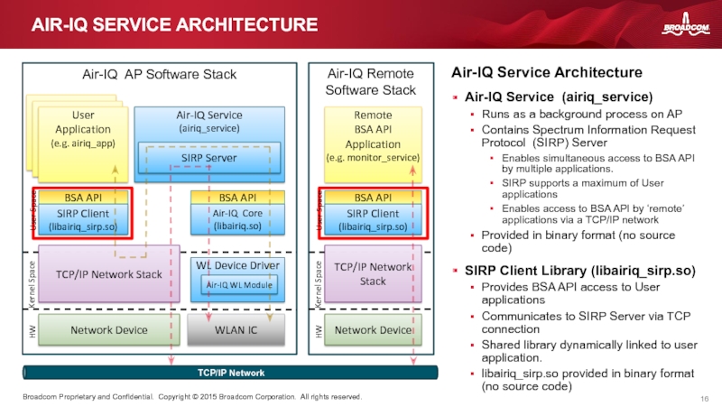
SIRP Client Library (libairiq_sirp.so)
Provides BSA API access to User applications
Communicates to SIRP Server via TCP connection
Shared library dynamically linked to user application.
libairiq_sirp.so provided in binary format (no source code)
Слайд 17Web Browser
Local App UI
AIR-IQ SERVICE ARCHITECTURE
Air-IQ Service Architecture
Air-IQ Local Application (Localapp.swf)
Simple
Interference Event Log (last 128 events)
Channel Quality Graph
Non-WiFi Channel Utilization graph
Designed to be embedded into AP’s web interface
Implemented as Adobe Flash Application.
Downloaded from AP to end user Web Browser
Runs in context of Web browser.
Provided in binary format (no source code)
WL Device Driver
Air-IQ WL Module
Air-IQ AP Software Stack
User
Application
(e.g. airiq_app)
Air-IQ Service
(airiq_service)
SIRP Server
Network Device
TCP/IP Network Stack
User Space
Kernel Space
HW
TCP/IP Network
SIRP Client
(libairiq_sirp.so)
Air-IQ Core
(libairiq.so)
BSA API
WLAN IC
BSA API
End User PC
Network Device
TCP/IP Network Stack
User Space
Kernel Space
HW
SIRP Client
BSA API
Слайд 18AIR-IQ LIBRARY ARCHITECTURE
WL Device Driver
Air-IQ WL Module
Air-IQ AP Software Stack
User
Application
Network Device
TCP/IP
User Space
Kernel Space
HW
Air-IQ Core
(libairiq.so)
BSA API
WLAN IC
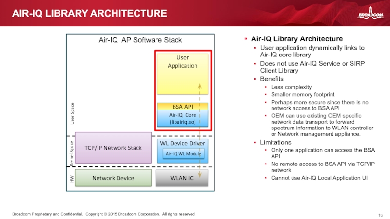
Air-IQ Library Architecture
User application dynamically links to Air-IQ core library
Does not use Air-IQ Service or SIRP Client Library
Benefits
Less complexity
Smaller memory footprint
Perhaps more secure since there is no network access to BSA API
OEM can use existing OEM specific network data transport to forward spectrum information to WLAN controller or Network management appliance.
Limitations
Only one application can access the BSA API
No remote access to BSA API via TCP/IP network
Cannot use Air-IQ Local Application UI
Слайд 20BSA = Broadcom Signal Analyzer
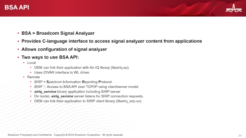
Provides C-language interface to access signal analyzer
Allows configuration of signal analyzer
Two ways to use BSA API:
Local
OEM can link their application with Air-IQ library (libairiq.so).
Uses IOVAR interface to WL driver.
Remote
SIRP = Spectrum Information Reporting Protocol.
SIRP ? Access to BSA API over TCP/IP using client/server model.
airiq_service binary application including SIRP server
On router, airiq_service server listens for SIRP connection requests.
OEM can link their application to SIRP client library (libairiq_sirp.so)
BSA API
Слайд 21Air-IQ AP Software Stack
BSA API
Application
(e.g. airiq_app)
Air-IQ Service
(airiq_service)
SIRP Server
WL
Device
Driver
Network Device
TCP/IP
User Space
Kernel Space
HW
TCP/IP Network
SIRP Client
(libairiq_sirp.so)
Air-IQ Core
(libairiq.so)
BSA API
BSA Device
BSA API
Air-IQ Remote Software Stack
Remote
BSA API
Application
(e.g. monitor_service)
Network Device
TCP/IP Network Stack
User Space
Kernel Space
HW
SIRP Client
(libairiq_sirp.so)
BSA API
BSA API IN AIR-IQ SOFTWARE STACK
Слайд 23Scanning is an essential part of Air-IQ.
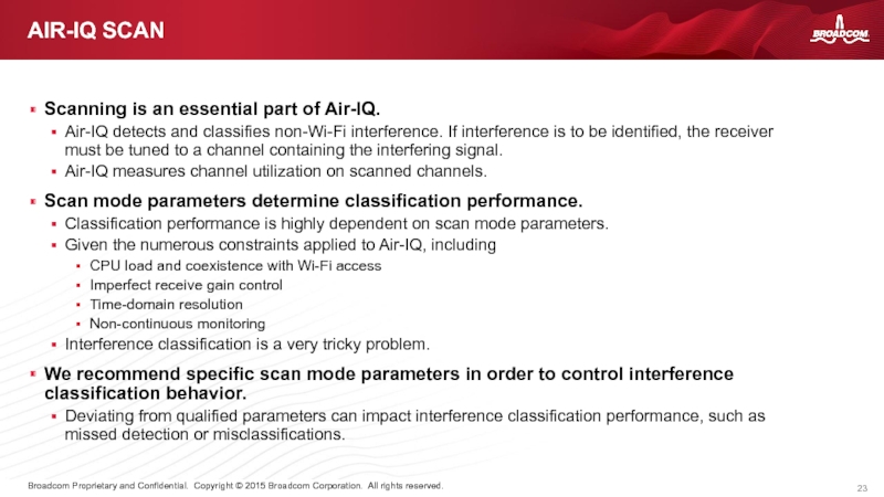
Air-IQ detects and classifies non-Wi-Fi
Air-IQ measures channel utilization on scanned channels.
Scan mode parameters determine classification performance.
Classification performance is highly dependent on scan mode parameters.
Given the numerous constraints applied to Air-IQ, including
CPU load and coexistence with Wi-Fi access
Imperfect receive gain control
Time-domain resolution
Non-continuous monitoring
Interference classification is a very tricky problem.
We recommend specific scan mode parameters in order to control interference classification behavior.
Deviating from qualified parameters can impact interference classification performance, such as missed detection or misclassifications.
AIR-IQ SCAN
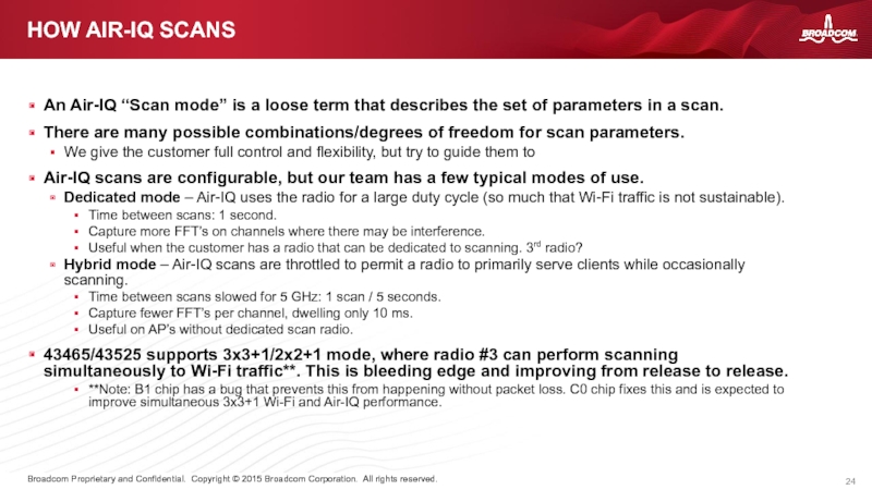
Слайд 24An Air-IQ “Scan mode” is a loose term that describes the
There are many possible combinations/degrees of freedom for scan parameters.
We give the customer full control and flexibility, but try to guide them to
Air-IQ scans are configurable, but our team has a few typical modes of use.
Dedicated mode – Air-IQ uses the radio for a large duty cycle (so much that Wi-Fi traffic is not sustainable).
Time between scans: 1 second.
Capture more FFT’s on channels where there may be interference.
Useful when the customer has a radio that can be dedicated to scanning. 3rd radio?
Hybrid mode – Air-IQ scans are throttled to permit a radio to primarily serve clients while occasionally scanning.
Time between scans slowed for 5 GHz: 1 scan / 5 seconds.
Capture fewer FFT’s per channel, dwelling only 10 ms.
Useful on AP’s without dedicated scan radio.
43465/43525 supports 3x3+1/2x2+1 mode, where radio #3 can perform scanning simultaneously to Wi-Fi traffic**. This is bleeding edge and improving from release to release.
**Note: B1 chip has a bug that prevents this from happening without packet loss. C0 chip fixes this and is expected to improve simultaneous 3x3+1 Wi-Fi and Air-IQ performance.
HOW AIR-IQ SCANS
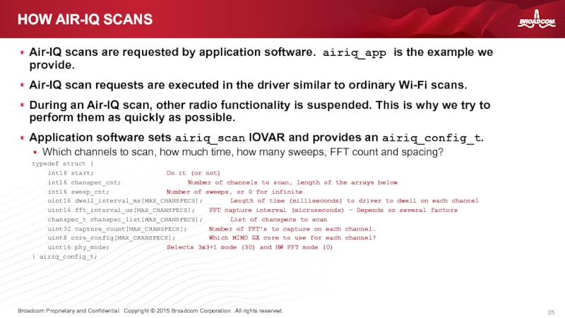
Слайд 25Air-IQ scans are requested by application software. airiq_app is the example
Air-IQ scan requests are executed in the driver similar to ordinary Wi-Fi scans.
During an Air-IQ scan, other radio functionality is suspended. This is why we try to perform them as quickly as possible.
Application software sets airiq_scan IOVAR and provides an airiq_config_t.
Which channels to scan, how much time, how many sweeps, FFT count and spacing?
typedef struct {
int16 start; Do it (or not)
int16 chanspec_cnt; Number of channels to scan, length of the arrays below
int16 sweep_cnt; Number of sweeps, or 0 for infinite
uint16 dwell_interval_ms[MAX_CHANSPECS]; Length of time (milliseconds) to driver to dwell on each channel
uint16 fft_interval_us[MAX_CHANSPECS]; FFT capture interval (microseconds) – Depends on several factors
chanspec_t chanspec_list[MAX_CHANSPECS]; List of chanspecs to scan
uint32 capture_count[MAX_CHANSPECS]; Number of FFT’s to capture on each channel.
uint8 core_config[MAX_CHANSPECS]; Which MIMO RX core to use for each channel?
uint16 phy_mode; Selects 3x3+1 mode (30) and HW FFT mode (0)
} airiq_config_t;
HOW AIR-IQ SCANS
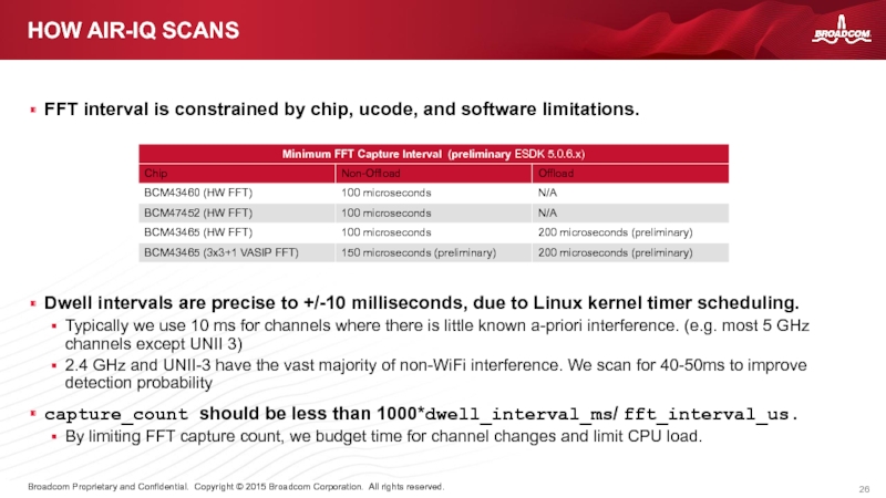
Слайд 26FFT interval is constrained by chip, ucode, and software limitations.
HOW AIR-IQ
Dwell intervals are precise to +/-10 milliseconds, due to Linux kernel timer scheduling.
Typically we use 10 ms for channels where there is little known a-priori interference. (e.g. most 5 GHz channels except UNII 3)
2.4 GHz and UNII-3 have the vast majority of non-WiFi interference. We scan for 40-50ms to improve detection probability
capture_count should be less than 1000*dwell_interval_ms/ fft_interval_us.
By limiting FFT capture count, we budget time for channel changes and limit CPU load.
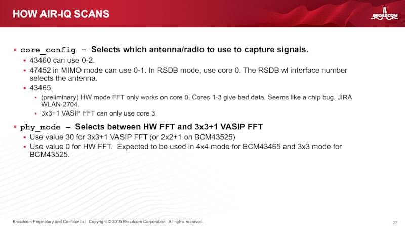
Слайд 27core_config – Selects which antenna/radio to use to capture signals.
43460 can
47452 in MIMO mode can use 0-1. In RSDB mode, use core 0. The RSDB wl interface number selects the antenna.
43465
(preliminary) HW mode FFT only works on core 0. Cores 1-3 give bad data. Seems like a chip bug. JIRA WLAN-2704.
3x3+1 VASIP FFT can only use core 3.
phy_mode – Selects between HW FFT and 3x3+1 VASIP FFT
Use value 30 for 3x3+1 VASIP FFT (or 2x2+1 on BCM43525)
Use value 0 for HW FFT. Expected to be used in 4x4 mode for BCM43465 and 3x3 mode for BCM43525.
HOW AIR-IQ SCANS
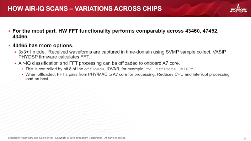
Слайд 28For the most part, HW FFT functionality performs comparably across 43460,
43465 has more options.
3x3+1 mode. Received waveforms are captured in time-domain using SVMP sample collect. VASIP PHYDSP firmware calculates FFT.
Air-IQ classification and FFT processing can be offloaded to onboard A7 core.
This is controlled by bit 8 of the offloads IOVAR, for example: “wl offloads 0x100”.
When offloaded, FFT’s pass from PHY/MAC to A7 core for processing. Reduces CPU and interrupt processing load on host.
HOW AIR-IQ SCANS – VARIATIONS ACROSS CHIPS
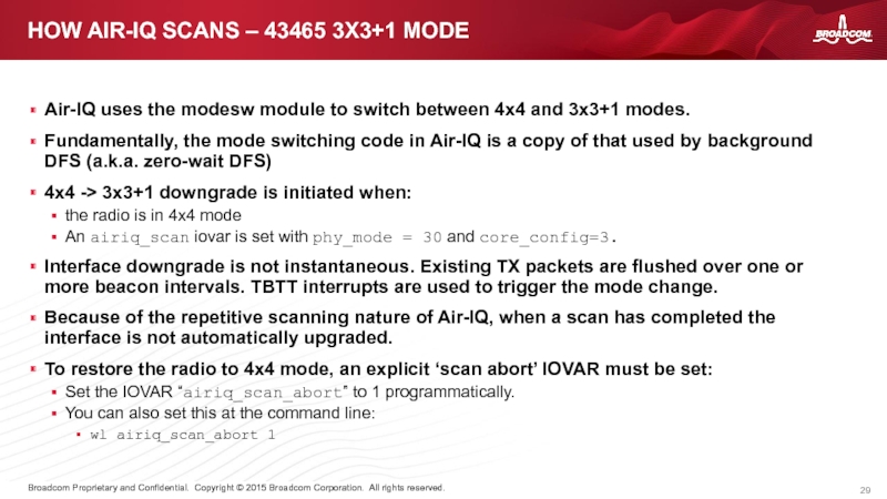
Слайд 29Air-IQ uses the modesw module to switch between 4x4 and 3x3+1
Fundamentally, the mode switching code in Air-IQ is a copy of that used by background DFS (a.k.a. zero-wait DFS)
4x4 -> 3x3+1 downgrade is initiated when:
the radio is in 4x4 mode
An airiq_scan iovar is set with phy_mode = 30 and core_config=3.
Interface downgrade is not instantaneous. Existing TX packets are flushed over one or more beacon intervals. TBTT interrupts are used to trigger the mode change.
Because of the repetitive scanning nature of Air-IQ, when a scan has completed the interface is not automatically upgraded.
To restore the radio to 4x4 mode, an explicit ‘scan abort’ IOVAR must be set:
Set the IOVAR “airiq_scan_abort” to 1 programmatically.
You can also set this at the command line:
wl airiq_scan_abort 1
HOW AIR-IQ SCANS – 43465 3X3+1 MODE
Слайд 30AIR-IQ SCANNING WITH PARAMETERS
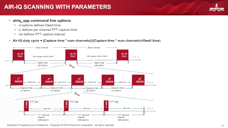
airiq_app command line options
-d options defines Dwell time
-c
-int defines FFT capture interval
Air-IQ duty cycle = (Capture time * num channels)/((Capture time * num channels)+Dwell time)
FFT #1
FFT #2
FFT #3
4 usec
4 usec
4 usec
1st channel
. . .
Air-IQ Scan
WiFi Access / WIDS / WIPS
. . .
Dwell time
(-d option)
2nd channel
Air-IQ Scan
Air-IQ Scan
3rd channel
. . .
4th channel
5th channel
WiFi Access / WIDS / WIPS
Слайд 31DEDICATED MODE – EXAMPLE 43460
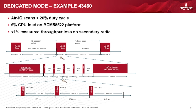
Air-IQ scans < 20% duty cycle
6% CPU
<1% measured throughput loss on secondary radio
FFT #1
FFT #2
FFT #3
4 usec
4 usec
4 usec
2.4GHz 7/80
450 FFT’s (45 ms)
42/80
58/80
106/80
122/80
138/80
5 GHZ 155/80
450 FFT’s (45 ms)
. . .
dead time
dead time
dead time
dead time
dead time
Air-IQ Scan
WIDS/WIPS
Air-IQ Scan
WIDS/WIPS
Air-IQ Scan
. . .
WiFi Access / WIDS / WIPS
Слайд 32HYBRID MODE – EXAMPLE 43460
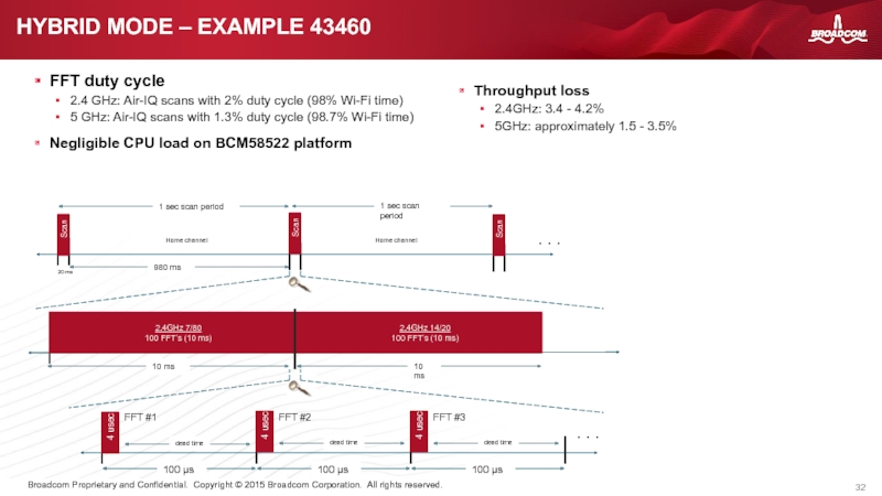
FFT duty cycle
2.4 GHz: Air-IQ scans with
5 GHz: Air-IQ scans with 1.3% duty cycle (98.7% Wi-Fi time)
Negligible CPU load on BCM58522 platform
FFT #1
FFT #2
FFT #3
4 usec
4 usec
4 usec
2.4GHz 7/80
100 FFT’s (10 ms)
. . .
Scan
Home channel
Home channel
. . .
20 ms
Scan
Scan
2.4GHz 14/20
100 FFT’s (10 ms)
Throughput loss
2.4GHz: 3.4 - 4.2%
5GHz: approximately 1.5 - 3.5%
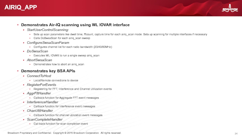
Слайд 34Demonstrates Air-IQ scanning using WL IOVAR interface
StartUserControlScanning:
Sets up scan parameters
Calls DoSwsaScan for each airiq_scan sweep
ConfigureSwsaScanParam
Configures channel list for each radio bandwidth (20/40/80MHz)
DoSwsaScan
Executes WL IOVAR to run a single sweep airiq_scan
AbortSwsaScan
Demonstrates how to abort an airiq_scan
Demonstrates key BSA APIs
ConnectToHost
Local/Remote connections to device
RegisterForEvents
Registering for FFT, Interference and Channel Utilization events
AggrFftHandler
Callback function for Aggregate FFT event messages
InterferenceHandler
Callback function for Interference event messages
ChanUtilHandler
Callback function for channel utilization event messages
ScanCompleteHandler
Call back function for scan completion event
AIRIQ_APP
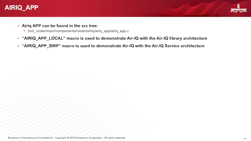
Слайд 35Airiq APP can be found in the src tree:
hnd_router/main/components/router/airiq/airiq_app/airiq_app.c
“AIRIQ_APP_LOCAL” macro
“AIRIQ_APP_SIRP” macro is used to demonstrate Air-IQ with the Air-IQ Service architecture
AIRIQ_APP
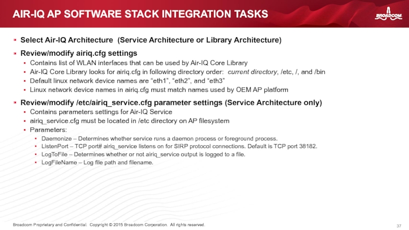
Слайд 37Select Air-IQ Architecture (Service Architecture or Library Architecture)
Review/modify airiq.cfg settings
Contains list
Air-IQ Core Library looks for airiq.cfg in following directory order: current directory, /etc, /, and /bin
Default linux network device names are “eth1”, “eth2”, and “eth3”
Linux network device names in airiq.cfg must match names used by OEM AP platform
Review/modify /etc/airiq_service.cfg parameter settings (Service Architecture only)
Contains parameters settings for Air-IQ Service
airiq_service.cfg must be located in /etc directory on AP filesystem
Parameters:
Daemonize – Determines whether service runs a daemon process or foreground process.
ListenPort – TCP port# airiq_service listens on for SIRP protocol connections. Default is TCP port 38182.
LogToFile – Determines whether or not airiq_service output is logged to a file.
LogFileName – Log file path and filename.
AIR-IQ AP SOFTWARE STACK INTEGRATION TASKS
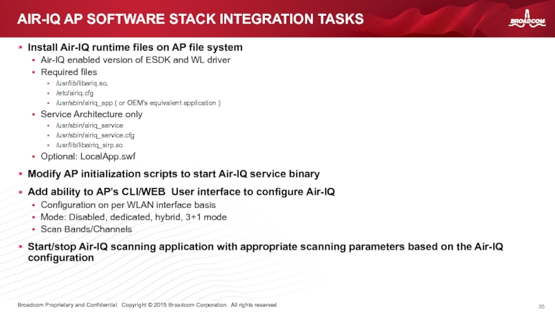
Слайд 38Install Air-IQ runtime files on AP file system
Air-IQ enabled version of
Required files
/usr/lib/libariq.so,
/etc/airiq.cfg
/usr/sbin/airiq_app ( or OEM’s equivalent application )
Service Architecture only
/usr/sbin/airiq_service
/usr/sbin/airiq_service.cfg
/usr/lib/libairiq_sirp.so
Optional: LocalApp.swf
Modify AP initialization scripts to start Air-IQ service binary
Add ability to AP’s CLI/WEB User interface to configure Air-IQ
Configuration on per WLAN interface basis
Mode: Disabled, dedicated, hybrid, 3+1 mode
Scan Bands/Channels
Start/stop Air-IQ scanning application with appropriate scanning parameters based on the Air-IQ configuration
AIR-IQ AP SOFTWARE STACK INTEGRATION TASKS
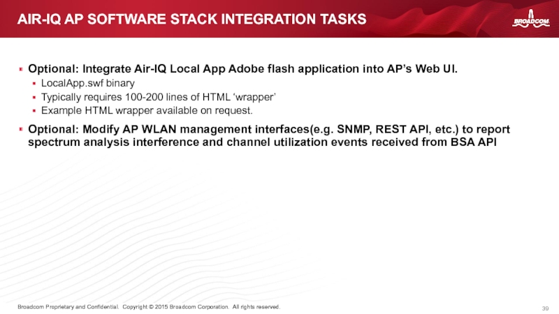
Слайд 39Optional: Integrate Air-IQ Local App Adobe flash application into AP’s Web
LocalApp.swf binary
Typically requires 100-200 lines of HTML ‘wrapper’
Example HTML wrapper available on request.
Optional: Modify AP WLAN management interfaces(e.g. SNMP, REST API, etc.) to report spectrum analysis interference and channel utilization events received from BSA API
AIR-IQ AP SOFTWARE STACK INTEGRATION TASKS
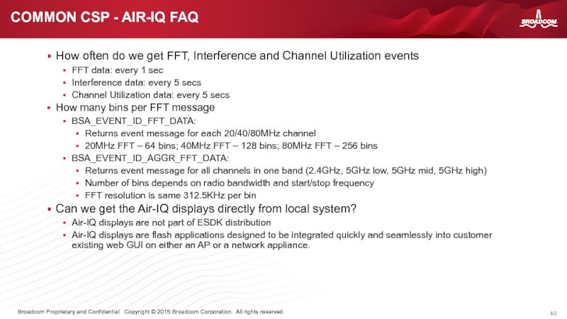
Слайд 40How often do we get FFT, Interference and Channel Utilization events
FFT
Interference data: every 5 secs
Channel Utilization data: every 5 secs
How many bins per FFT message
BSA_EVENT_ID_FFT_DATA:
Returns event message for each 20/40/80MHz channel
20MHz FFT – 64 bins; 40MHz FFT – 128 bins; 80MHz FFT – 256 bins
BSA_EVENT_ID_AGGR_FFT_DATA:
Returns event message for all channels in one band (2.4GHz, 5GHz low, 5GHz mid, 5GHz high)
Number of bins depends on radio bandwidth and start/stop frequency
FFT resolution is same 312.5KHz per bin
Can we get the Air-IQ displays directly from local system?
Air-IQ displays are not part of ESDK distribution
Air-IQ displays are flash applications designed to be integrated quickly and seamlessly into customer existing web GUI on either an AP or a network appliance.
COMMON CSP - AIR-IQ FAQ
Слайд 41Performance issues
How high is CPU utilization?
4x4 mode: < 10% on
3+1 mode: < 10% on scan CPU 1
How many threads are used by airiq library/airiq_service
Air-IQ Core Library uses 4 threads
Air-IQ Service uses 12 threads
How much memory does Air-IQ use?
Driver uses ~4MB
Classification issues
For any classification issues force customer to use “Classification Debug Capture” tool
Most common setup issues
Antennas side-by side touching, or lying on the PCB itself. Make sure to mount antennas on a backing plate
Antennas/AP placed near other electronic equipment
We expect in an enterprise deployment AP’s to be mounted on walls, ceilings, poles, etc, but not immediately next to another AP or desktop computer. Place the DUT a reasonable distance from other electronic equipment that may unintentionally radiate.
Air-IQ is sensitive to interference (its purpose) and it will pick up unintentional RF emissions from these devices when placed very close by.
Bad U.FL cables, or no antennas attached at all will cause us grief.
Check U.FL cables and antennae if Air-IQ reports interference while nothing is turned on.
It’s common to have bad U.FL cables or antenna
While testing Bluetooth ensure that music/data is streaming to headphones/bluetooth device.
While testing Microwave Oven make sure something is cooking! Place a bowl of water in the oven.
COMMON CSP – PERFORMANCE AND CLASSIFICATION
