- Главная
- Разное
- Дизайн
- Бизнес и предпринимательство
- Аналитика
- Образование
- Развлечения
- Красота и здоровье
- Финансы
- Государство
- Путешествия
- Спорт
- Недвижимость
- Армия
- Графика
- Культурология
- Еда и кулинария
- Лингвистика
- Английский язык
- Астрономия
- Алгебра
- Биология
- География
- Детские презентации
- Информатика
- История
- Литература
- Маркетинг
- Математика
- Медицина
- Менеджмент
- Музыка
- МХК
- Немецкий язык
- ОБЖ
- Обществознание
- Окружающий мир
- Педагогика
- Русский язык
- Технология
- Физика
- Философия
- Химия
- Шаблоны, картинки для презентаций
- Экология
- Экономика
- Юриспруденция
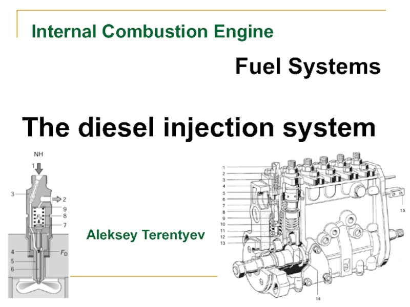
Internal Сombustion Engine. Fuel Systems. The diesel injection system презентация
Содержание
- 1. Internal Сombustion Engine. Fuel Systems. The diesel injection system
- 2. Basic Functions of Injection Systems The basic
- 3. Basic Functions of Injection Systems 3. Fuel
- 4. Types of Injection Systems The basic
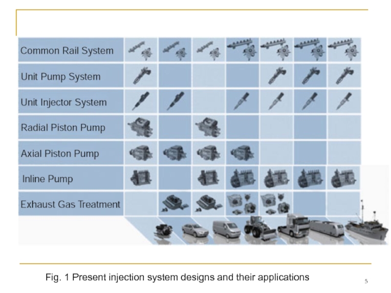
- 5. Fig. 1 Present injection system designs and their applications
- 6. Types of Injection Systems Accumulator systems on
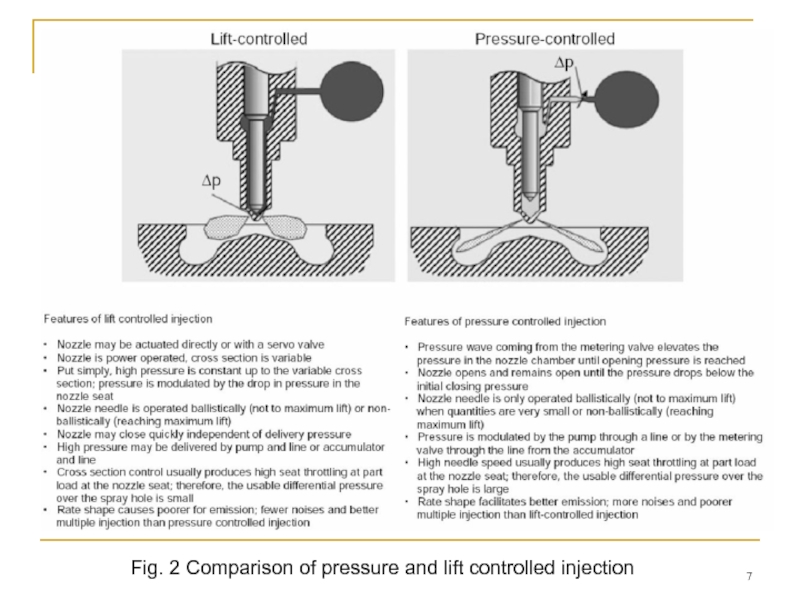
- 7. Fig. 2 Comparison of pressure and lift controlled injection
- 8. Types The implementation of common rail systems
- 9. Inline Pumps Main Features – There is
- 10. Axial Distributor Pumps Main Features – There
- 11. Radial Distributor Pumps – The fuel flow
- 12. Unit Injectors (Unit Injectors) Main Features –
- 13. Unit Pump Systems (Unit Pumps) – It
- 14. Common Rail System – One injector (body
- 15. Common Rail System Design Unlike cam-driven injection
- 16. A common rail system can be divided
- 17. Common Rail System Design Driven by the
- 18. CR Injectors Common rail injectors with identical
- 19. Solenoid Valve Injector. Design Configuration An injector
- 20. Solenoid Valve Injector. Function The injector’s function
- 21. Fig. 10 b Solenoid valve injector
- 22. Injector opened: The nozzle needle’s opening speed
- 23. Injector closes (end of injection): When the
Слайд 2Basic Functions of Injection Systems
The basic functions of a diesel injection
1. Fuel delivery (low pressure side) from the tank through the fuel filter to high pressure generation. This function is assumed by the ‘‘low pressure circuit’’ subsystem, which is generally equipped with the components of pre-filter, main filter (heated if necessary), feed pump and control valves.
The low pressure circuit connects the vehicle tank to the high pressure system feed and return by lines through the low pressure components. The functionally determinative pressure and flow specifications of the connected high and low pressure components must be observed.
2. High pressure generation and fuel delivery (high pressure side) to the metering point or in an accumulator with high efficiency during compression. Optimal steady state and dynamic injection pressure both have to be provided as a function of the engine operating point. The required injected fuel quantity and system-dependent control and leak quantities have to be delivered. This function is assumed by the high pressure pump and, depending on the system, an accumulator. Valves are installed in the high pressure circuit to control the mass flows and pressures. In advanced injection systems, they are electronically actuated.
Слайд 3Basic Functions of Injection Systems
3. Fuel metering that precisely meters the
4. Fuel preparation by optimally utilizing the pressure energy for primary mixture formation for the purpose of a fluid spray that is optimally distributed in the combustion chamber in terms of time and location. The fuel is prepared in the injection nozzle. The metering valve’s interaction with the nozzle needle control and the routing of the flow from the nozzle inlet until its discharge at the nozzle holes are of key importance.
Слайд 4Types of Injection Systems
The basic functions described above are implemented differently
Figure 1 presents an overview of commercially available injection systems and typical fields of application.
An initial distinction must be made between conventionally designed systems and systems with high pressure accumulators. Injection systems without accumulators always have high pressure pump plungers driven directly by a cam and thus generate a pressure wave in the high pressure system, which is directly utilized to open the injection nozzle and inject the fuel cylinder-selectively according to the firing sequence.
The next level of classification includes systems with a ‘‘central injection pump’’ that serves every cylinder and delivers and meters the fuel. Typical representatives are inline pumps and distributor pumps with axial and radial pump elements.
The other design is characterized by ‘‘detached injection pumps per engine cylinder’’. One discrete pressure generation unit driven by the engine camshaft is attached for every one of the combustion engine’s cylinders. The fuel is metered by rapidly switching solenoid valves integrated in the pump unit. The unit injector is one familiar example of this type of injection system.
Слайд 6Types of Injection Systems
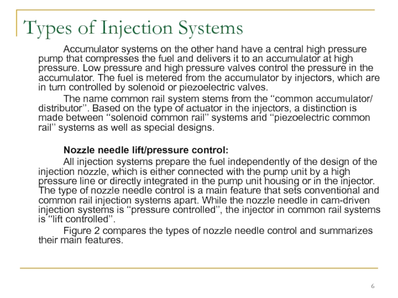
Accumulator systems on the other hand have a
The name common rail system stems from the ‘‘common accumulator/ distributor’’. Based on the type of actuator in the injectors, a distinction is made between ‘‘solenoid common rail’’ systems and ‘‘piezoelectric common rail’’ systems as well as special designs.
Nozzle needle lift/pressure control:
All injection systems prepare the fuel independently of the design of the injection nozzle, which is either connected with the pump unit by a high pressure line or directly integrated in the pump unit housing or in the injector. The type of nozzle needle control is a main feature that sets conventional and common rail injection systems apart. While the nozzle needle in cam-driven injection systems is ‘‘pressure controlled’’, the injector in common rail systems is ‘‘lift controlled’’.
Figure 2 compares the types of nozzle needle control and summarizes their main features.
Слайд 8Types
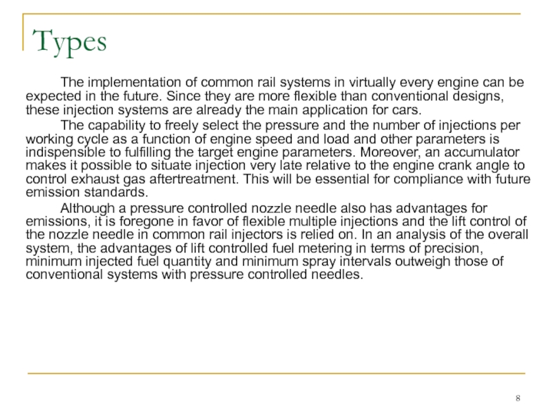
The implementation of common rail systems in virtually every engine can
The capability to freely select the pressure and the number of injections per working cycle as a function of engine speed and load and other parameters is indispensible to fulfilling the target engine parameters. Moreover, an accumulator makes it possible to situate injection very late relative to the engine crank angle to control exhaust gas aftertreatment. This will be essential for compliance with future emission standards.
Although a pressure controlled nozzle needle also has advantages for emissions, it is foregone in favor of flexible multiple injections and the lift control of the nozzle needle in common rail injectors is relied on. In an analysis of the overall system, the advantages of lift controlled fuel metering in terms of precision, minimum injected fuel quantity and minimum spray intervals outweigh those of conventional systems with pressure controlled needles.
Слайд 9Inline Pumps
Main Features
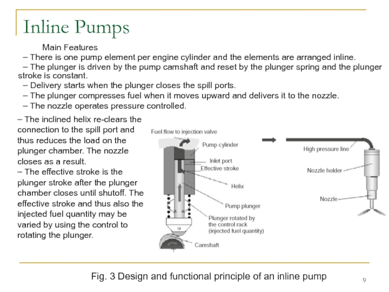
– There is one pump element per engine cylinder
– The plunger is driven by the pump camshaft and reset by the plunger spring and the plunger stroke is constant.
– Delivery starts when the plunger closes the spill ports.
– The plunger compresses fuel when it moves upward and delivers it to the nozzle.
– The nozzle operates pressure controlled.
– The inclined helix re-clears the connection to the spill port and thus reduces the load on the plunger chamber. The nozzle closes as a result.
– The effective stroke is the plunger stroke after the plunger chamber closes until shutoff. The effective stroke and thus also the injected fuel quantity may be varied by using the control to rotating the plunger.
Fig. 3 Design and functional principle of an inline pump
Слайд 10Axial Distributor Pumps
Main Features
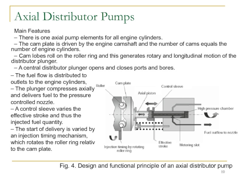
– There is one axial pump elements for
– The cam plate is driven by the engine camshaft and the number of cams equals the number of engine cylinders.
– Cam lobes roll on the roller ring and this generates rotary and longitudinal motion of the distributor plunger.
– A central distributor plunger opens and closes ports and bores.
– The fuel flow is distributed to outlets to the engine cylinders,
– The plunger compresses axially and delivers fuel to the pressure controlled nozzle.
– A control sleeve varies the effective stroke and thus the injected fuel quantity.
– The start of delivery is varied by an injection timing mechanism, which rotates the roller ring relative to the cam plate.
Fig. 4. Design and functional principle of an axial distributor pump
Слайд 11Radial Distributor Pumps
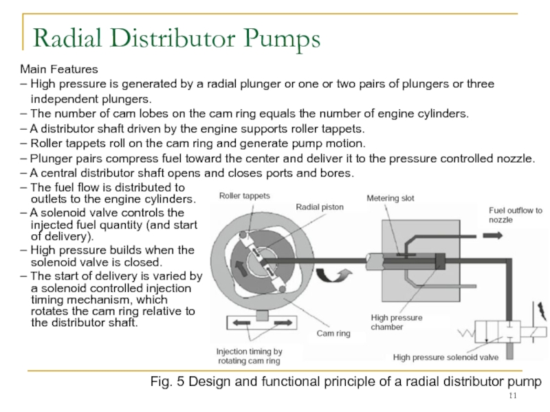
– The fuel flow is distributed to outlets to
– A solenoid valve controls the injected fuel quantity (and start of delivery).
– High pressure builds when the solenoid valve is closed.
– The start of delivery is varied by a solenoid controlled injection timing mechanism, which rotates the cam ring relative to the distributor shaft.
Main Features
– High pressure is generated by a radial plunger or one or two pairs of plungers or three independent plungers.
– The number of cam lobes on the cam ring equals the number of engine cylinders.
– A distributor shaft driven by the engine supports roller tappets.
– Roller tappets roll on the cam ring and generate pump motion.
– Plunger pairs compress fuel toward the center and deliver it to the pressure controlled nozzle.
– A central distributor shaft opens and closes ports and bores.
Fig. 5 Design and functional principle of a radial distributor pump
Слайд 12Unit Injectors (Unit Injectors)
Main Features
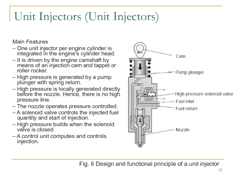
– One unit injector per engine cylinder
– It is driven by the engine camshaft by means of an injection cam and tappet or roller rocker.
– High pressure is generated by a pump plunger with spring return.
– High pressure is locally generated directly before the nozzle. Hence, there is no high pressure line.
– The nozzle operates pressure controlled.
– A solenoid valve controls the injected fuel quantity and start of injection.
– High pressure builds when the solenoid valve is closed.
– A control unit computes and controls injection.
Fig. 6 Design and functional principle of a unit injector
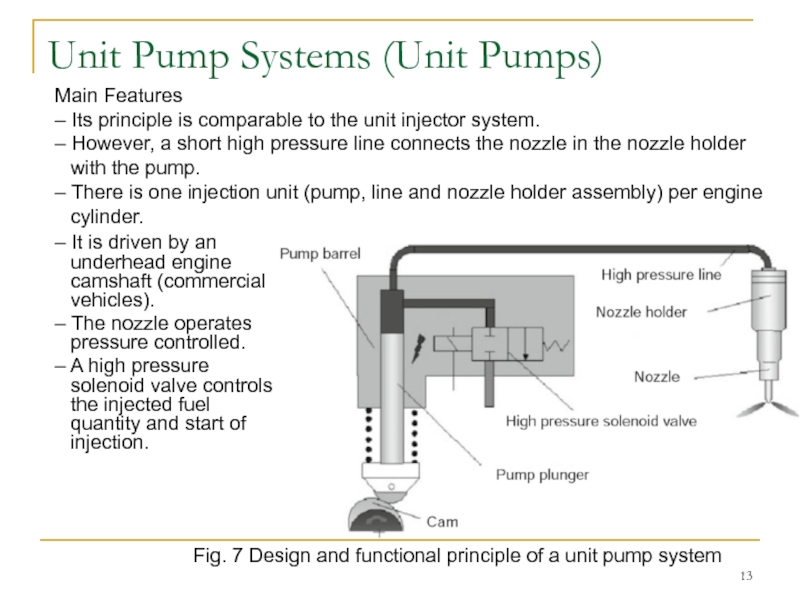
Слайд 13Unit Pump Systems (Unit Pumps)
– It is driven by an underhead
– The nozzle operates pressure controlled.
– A high pressure solenoid valve controls the injected fuel quantity and start of injection.
Main Features
– Its principle is comparable to the unit injector system.
– However, a short high pressure line connects the nozzle in the nozzle holder with the pump.
– There is one injection unit (pump, line and nozzle holder assembly) per engine cylinder.
Fig. 7 Design and functional principle of a unit pump system
Слайд 14Common Rail System
– One injector (body with nozzle and control valve
– The nozzle operates lift controlled.
– The injector operates time controlled and the injected fuel quantity is a function of the rail pressure and duration of control.
– A control unit controls the number and position of injections and the injected fuel quantity.
Fig. 8 Design and functional principle of a common rail system
Main Features
– It is an accumulator injection system.
– High pressure generation and injection are decoupled.
– A central high pressure pump generates pressure in the accumulator, which may be adjusted in the entire map independent of engine speed and load.
– Repeated extraction of fuel from the rail per working cycle of the engine allows high flexibility of the position, number and size of injections.
Слайд 15Common Rail System Design
Unlike cam-driven injection systems, the common rail system
– continually available speed and load-independent injection pressure allows flexibly selecting the start of injection, the injected fuel quantity and the duration of injection,
– high injection pressures and thus good mixture formation are possible even at lower speeds and loads,
– it provides high flexibility for multiple injections,
– it is easily mounted on the engine and
– drive torque peaks are significantly lower.
Common rail systems are employed in all DI engine applications for cars and commercial vehicles (on and off-highway).
Maximum system pressures are 1,800 bar. Systems for pressures > 2,000 bar are in development.
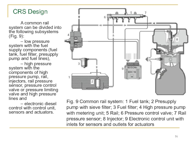
Слайд 16 A common rail system can be divided into the following subsystems
– low pressure system with the fuel supply components (fuel tank, fuel filter, presupply pump and fuel lines),
– high pressure system with the components of high pressure pump, rail, injectors, rail pressure sensor, pressure control valve or pressure limiting valve and high pressure lines and
– electronic diesel control with control unit, sensors and actuators.
Fig. 9 Common rail system: 1 Fuel tank; 2 Presupply
pump with sieve filter; 3 Fuel filter; 4 High pressure pump with metering unit; 5 Rail; 6 Pressure control valve; 7 Rail pressure sensor; 8 Injector; 9 Electronic control unit with inlets for sensors and outlets for actuators
CRS Design
Слайд 17Common Rail System Design
Driven by the engine, the continuously operating high
The high pressure pump is designed as a radial piston pump and, for commercial vehicles, partly as an inline or single plunger pump (driven by the engine camshaft). Various modes are employed to control rail pressure. The pressure may be controlled on the high pressure side by a pressure control valve or on the low pressure side by a metering unit integrated in the pump (housed in a separate component for single plunger pumps). Dual actuator systems combine the advantages of both systems. Short high pressure lines connect the injectors with the rail. The engine control unit controls the solenoid valve integrated in the injector to open and reclose the injection nozzle. The opening time and system pressure determine the injected fuel quantity. At constant pressure, it is proportional to the time the solenoid valve is switched on and thus independent of engine and pump speed.
A basic distinction is made between systems with and without pressure amplification. In systems with pressure amplification, a stepped piston in the injector amplifies the pressure generated by the high pressure pump. The injection characteristic can be shaped flexibly when the pressure intensifier is separately controllable by its own solenoid valve. The systems predominantly in use today operate without pressure amplification.
Слайд 18CR Injectors
Common rail injectors with identical basic functions are employed in
Injectors in a common rail diesel injection system are connected with the rail by short high pressure fuel lines. A copper gasket seals the injectors from the combustion chamber. Clamping elements attach the injectors in the cylinder head. Common rail injectors are suited for straight or oblique installation in direct injection diesel engines, depending on the design of the injection nozzles.
The system characteristically generates injection pressure independent of the engine speed and the injected fuel quantity. The electrically controllable injector controls the start of injection and the injected fuel quantity. The electronic diesel control’s (EDC) angle-time function controls the injection timing. It requires two sensors on the crankshaft and on the camshaft for cylinder recognition (phase detection).
Various types of injectors are currently standard:
– solenoid valve (SV) injectors with a one or two-piece armature (Bosch),
– inline SV injectors (Delphi),
– tophead piezo injectors (Siemens) and inline piezo injectors (Bosch, Denso).
Слайд 19Solenoid Valve Injector. Design
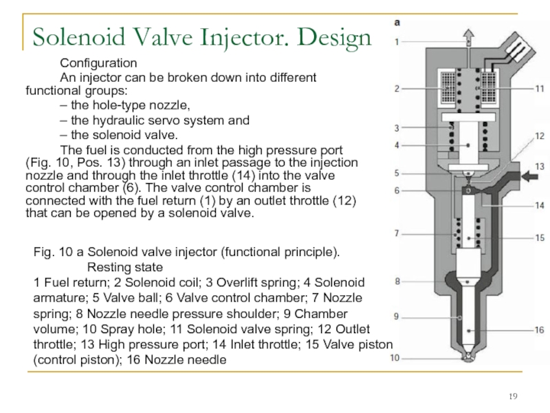
Configuration
An injector can be broken down into different
– the hole-type nozzle,
– the hydraulic servo system and
– the solenoid valve.
The fuel is conducted from the high pressure port (Fig. 10, Pos. 13) through an inlet passage to the injection nozzle and through the inlet throttle (14) into the valve control chamber (6). The valve control chamber is connected with the fuel return (1) by an outlet throttle (12) that can be opened by a solenoid valve.
Fig. 10 a Solenoid valve injector (functional principle).
Resting state
1 Fuel return; 2 Solenoid coil; 3 Overlift spring; 4 Solenoid armature; 5 Valve ball; 6 Valve control chamber; 7 Nozzle spring; 8 Nozzle needle pressure shoulder; 9 Chamber volume; 10 Spray hole; 11 Solenoid valve spring; 12 Outlet throttle; 13 High pressure port; 14 Inlet throttle; 15 Valve piston (control piston); 16 Nozzle needle
Слайд 20Solenoid Valve Injector. Function
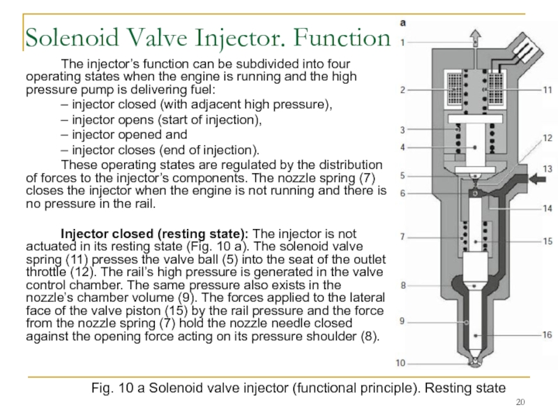
The injector’s function can be subdivided into four
– injector closed (with adjacent high pressure),
– injector opens (start of injection),
– injector opened and
– injector closes (end of injection).
These operating states are regulated by the distribution of forces to the injector’s components. The nozzle spring (7) closes the injector when the engine is not running and there is no pressure in the rail.
Injector closed (resting state): The injector is not actuated in its resting state (Fig. 10 a). The solenoid valve spring (11) presses the valve ball (5) into the seat of the outlet throttle (12). The rail’s high pressure is generated in the valve control chamber. The same pressure also exists in the nozzle’s chamber volume (9). The forces applied to the lateral face of the valve piston (15) by the rail pressure and the force from the nozzle spring (7) hold the nozzle needle closed against the opening force acting on its pressure shoulder (8).
Fig. 10 a Solenoid valve injector (functional principle). Resting state
Слайд 21
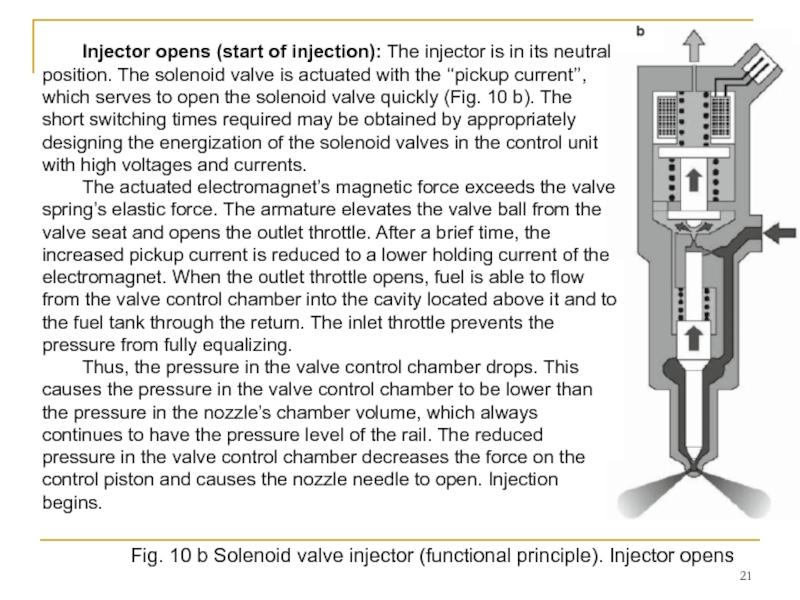
Fig. 10 b Solenoid valve injector (functional principle). Injector opens
Injector opens
The actuated electromagnet’s magnetic force exceeds the valve spring’s elastic force. The armature elevates the valve ball from the valve seat and opens the outlet throttle. After a brief time, the increased pickup current is reduced to a lower holding current of the electromagnet. When the outlet throttle opens, fuel is able to flow from the valve control chamber into the cavity located above it and to the fuel tank through the return. The inlet throttle prevents the pressure from fully equalizing.
Thus, the pressure in the valve control chamber drops. This causes the pressure in the valve control chamber to be lower than the pressure in the nozzle’s chamber volume, which always continues to have the pressure level of the rail. The reduced pressure in the valve control chamber decreases the force on the control piston and causes the nozzle needle to open. Injection begins.
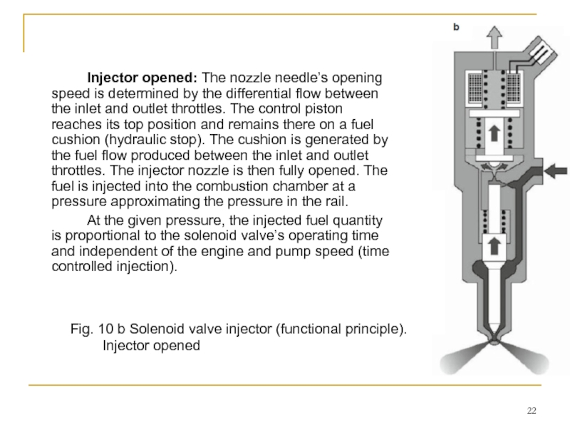
Слайд 22 Injector opened: The nozzle needle’s opening speed is determined by the
At the given pressure, the injected fuel quantity is proportional to the solenoid valve’s operating time and independent of the engine and pump speed (time controlled injection).
Fig. 10 b Solenoid valve injector (functional principle). Injector opened
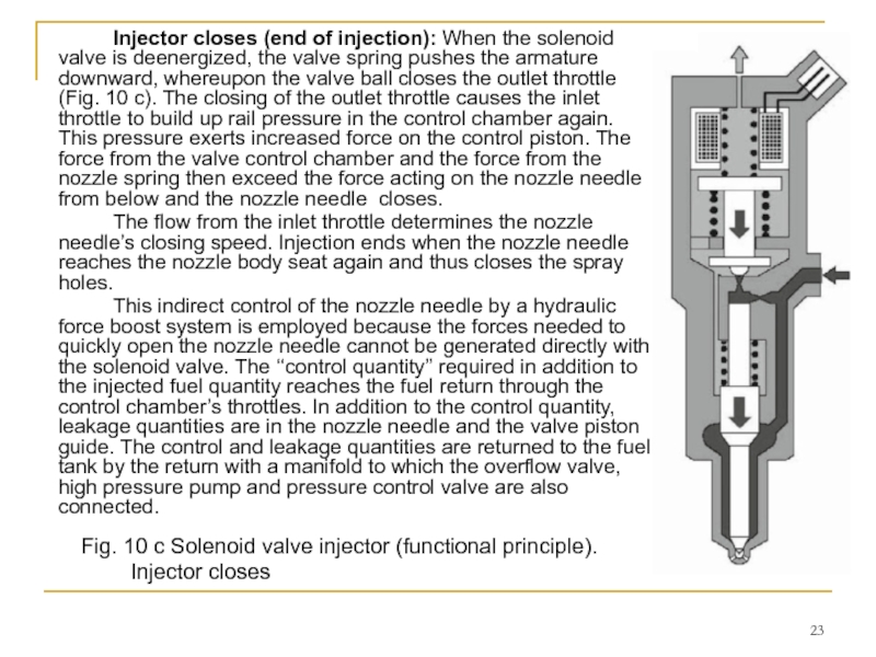
Слайд 23 Injector closes (end of injection): When the solenoid valve is deenergized,
The flow from the inlet throttle determines the nozzle needle’s closing speed. Injection ends when the nozzle needle reaches the nozzle body seat again and thus closes the spray holes.
This indirect control of the nozzle needle by a hydraulic force boost system is employed because the forces needed to quickly open the nozzle needle cannot be generated directly with the solenoid valve. The ‘‘control quantity’’ required in addition to the injected fuel quantity reaches the fuel return through the control chamber’s throttles. In addition to the control quantity, leakage quantities are in the nozzle needle and the valve piston guide. The control and leakage quantities are returned to the fuel tank by the return with a manifold to which the overflow valve, high pressure pump and pressure control valve are also connected.
Fig. 10 c Solenoid valve injector (functional principle).
Injector closes
![Common Rail System– One injector (body with nozzle and control valve [solenoid or piezo actuator])](/img/tmb/4/357563/016d1e6819541ac094bde066e47a248d-800x.jpg)
