- Главная
- Разное
- Дизайн
- Бизнес и предпринимательство
- Аналитика
- Образование
- Развлечения
- Красота и здоровье
- Финансы
- Государство
- Путешествия
- Спорт
- Недвижимость
- Армия
- Графика
- Культурология
- Еда и кулинария
- Лингвистика
- Английский язык
- Астрономия
- Алгебра
- Биология
- География
- Детские презентации
- Информатика
- История
- Литература
- Маркетинг
- Математика
- Медицина
- Менеджмент
- Музыка
- МХК
- Немецкий язык
- ОБЖ
- Обществознание
- Окружающий мир
- Педагогика
- Русский язык
- Технология
- Физика
- Философия
- Химия
- Шаблоны, картинки для презентаций
- Экология
- Экономика
- Юриспруденция
Tool and Spindle Calibration презентация
Содержание
- 1. Tool and Spindle Calibration
- 3. Why to calibrate a spindle? Robots need
- 4. Objectives The objective of the spindle calibration
- 5. 2. Three probes / spikes One
- 6. Step 1: Create a new spindle calibration
- 7. Step 2: Teach short probe (Example
- 8. Step 2: Teach short probe. Measure 1/3
- 9. Step 2: Teach short probe. Measure 2/3 And for the second ‘teach’:
- 10. Step 2: Teach short probe. Measure 3/3 Finally for the third ‘teach’:
- 11. Step 3: Measure short probe length
- 12. Step 4: Measure long probe The
- 13. Step 4: Teach long probe. Measure 1/3
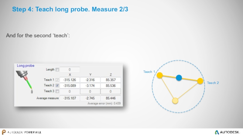
- 14. Step 4: Teach long probe. Measure 2/3 And for the second ‘teach’:
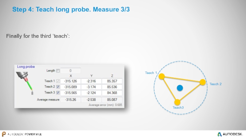
- 15. Step 4: Teach long probe. Measure 3/3 Finally for the third ‘teach’:
- 16. Step 5: Measure long probe length
- 17. Step 6: Define tool workplane orientation This
- 18. Spindle information… Spindle direction (tool workplane) Spindle
- 19. Step 7: Measure cutting tool length The
- 20. Tool information is displayed 149.746
- 21. Tool length database Tool length can
- 22. Step 8: Update CAD & simulation
- 23. Autodesk ® PowerMill ® Robot Part on robot / External static spindle
- 24. Part-on-robot / External static spindle This will
- 25. The same as above needs to be
Слайд 3Why to calibrate a spindle?
Robots need to be taught about tools
During the teaching procedure, the robot determines where the tool tip center point is, in relation to its 6th axis workplane (in the case where the spindle is mounted on the robot).
This procedure must be repeated for each tool. This means that each tool will contain errors due to the inaccuracy of the teaching process.
Teaching the same tool twice will not give the same result. This is because the process is very visual, so the user will always introduce “human errors”.
Any errors incurred during the teaching stage will be dramatically amplified and will reduce machining accuracy.
The spindle calibration procedure has several key benefits:
It helps to improve machining accuracy
It reduces setup times
It removes the need to physically teach each tool
With this functionality, the robot is closer in behavior to a CNC machine.
Слайд 4Objectives
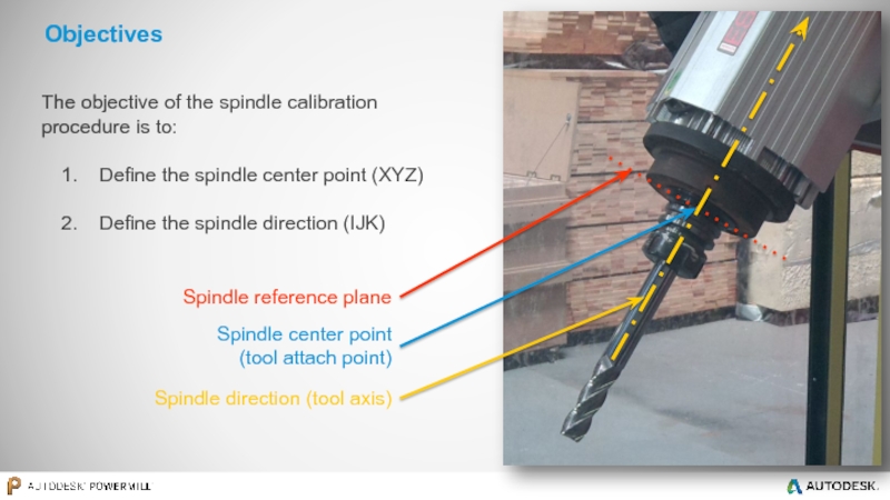
The objective of the spindle calibration procedure is to:
Define the
Define the spindle direction (IJK)
Spindle center point (tool attach point)
Spindle reference plane
Spindle direction (tool axis)
Слайд 52. Three probes / spikes
One long probe (spike)
One short
A third spike (used for teaching)
3. A tool measuring device
1. PowerMill Robot with the robot simulation loaded
Requirements to perform a spindle calibration
Слайд 6Step 1: Create a new spindle calibration
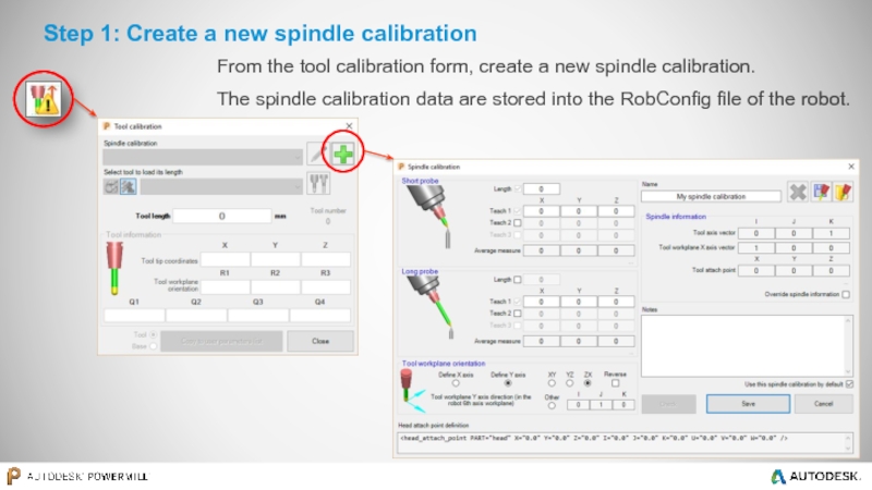
From the tool calibration form,
The spindle calibration data are stored into the RobConfig file of the robot.
Слайд 7Step 2: Teach short probe (Example based on a robot
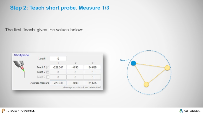
Teaching is required at least once but more times will give better accuracy. This is because PowerMill Robot will use their average. The three ‘teach’ method is the best…
Once taught, the robot can display the X, Y and Z coordinates of the probe tip, in relation to the 6th axis workplane (flange) of the robot *.
These coordinates will be used by the spindle calibration form.
* If the part is held by the robot (the spindle is on the table), the X,Y and Z coordinates of the probe tip teach are displayed, on the teach pendant, in relation to the robot world workplane.
The short probe must be taught as it would be for any other tool that the user wishes to use with the robot (usually using a “4 or 5 points method”). The values we are looking at are the coordinates (XYZ) of the tip of the probe.
Слайд 11Step 3: Measure short probe length
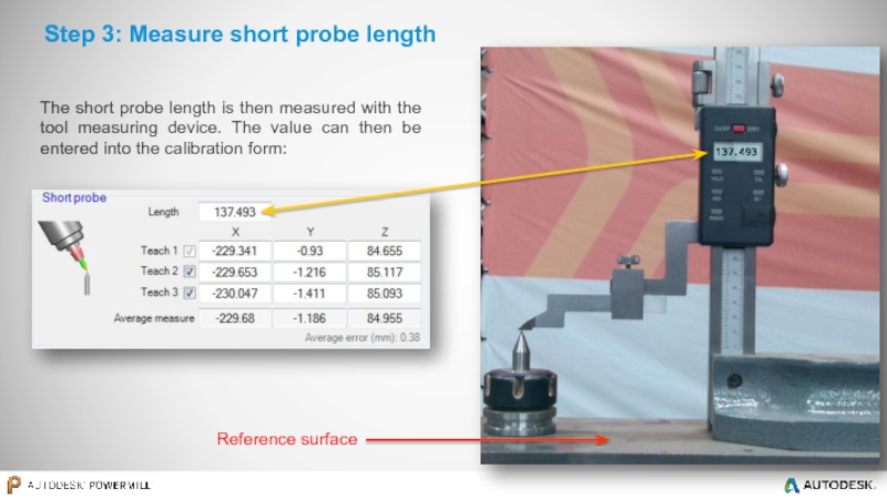
The short probe length is then
137.493
Reference surface
Слайд 16Step 5: Measure long probe length
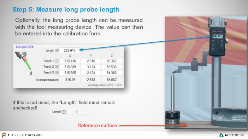
222.915
If this is not used, the
Reference surface
Optionally, the long probe length can be measured with the tool measuring device. The value can then be entered into the calibration form:
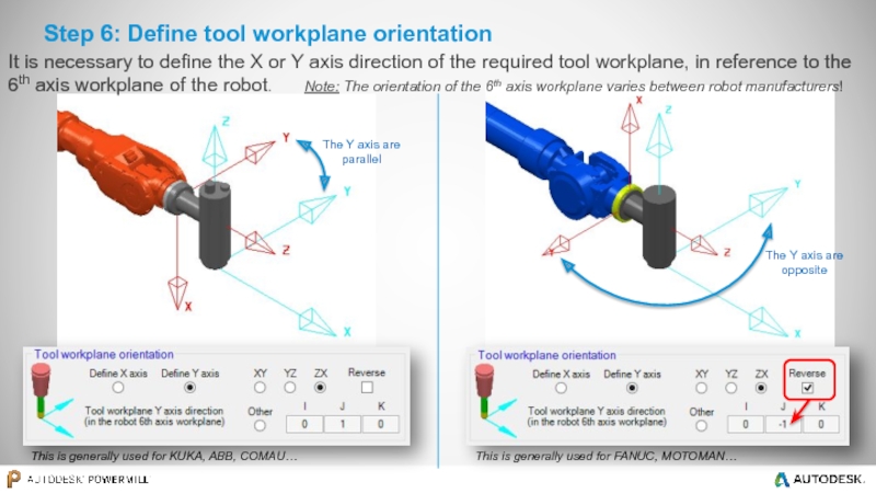
Слайд 17Step 6: Define tool workplane orientation
This is generally used for KUKA,
This is generally used for FANUC, MOTOMAN…
It is necessary to define the X or Y axis direction of the required tool workplane, in reference to the 6th axis workplane of the robot. Note: The orientation of the 6th axis workplane varies between robot manufacturers!
Слайд 18Spindle information…
Spindle direction (tool workplane)
Spindle center point
Create the “spindle workplane” measured
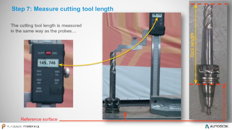
Слайд 19Step 7: Measure cutting tool length
The cutting tool length is measured
Reference surface
149.746
149.746
Tool length
Слайд 20Tool information is displayed
149.746
This information should go in the robot controller
In this case the tool length was 149.746 mm
The coordinates are referring to the robot 6th axis workplane (flange) as the spindle is mounted on the robot (for this example)
Values are displayed in the robot manufacturer specific convention (Euler/Quaternion/…)
Слайд 21Tool length database
Tool length can be stored in the tool length
Tool length database
Слайд 22Step 8: Update CAD & simulation
For the most accurate simulation the
In some cases it may be advisable to adapt the CAD data of the robot simulation.
Слайд 24Part-on-robot / External static spindle
This will give the position of the
The robot teach pendant can usually show the position of the tooltip from the robot world workplane and this is what we will use next.
Step 1: Teach the spike on the robot like a standard tool, against a fixed spike
(usually using a “4 or 5 points method”)
Step 2: Switch the teach pendant display to show tooltip coordinate from robot world workplane
Слайд 25The same as above needs to be done with the long
The short and long spike as well as the cutting tools are measured in the usual way (as described earlier).
Part-on-robot / External static spindle
Moving the previously taught robot spike tip against the short probe tip will show, on the robot teach pendant, the position of the short spike tip from the robot world workplane.
These are the XYZ coordinates to use in the spindle calibration form.
Step 3: Measure the short spike tip position
Step 4: Measure the long spike tip position
