- Главная
- Разное
- Дизайн
- Бизнес и предпринимательство
- Аналитика
- Образование
- Развлечения
- Красота и здоровье
- Финансы
- Государство
- Путешествия
- Спорт
- Недвижимость
- Армия
- Графика
- Культурология
- Еда и кулинария
- Лингвистика
- Английский язык
- Астрономия
- Алгебра
- Биология
- География
- Детские презентации
- Информатика
- История
- Литература
- Маркетинг
- Математика
- Медицина
- Менеджмент
- Музыка
- МХК
- Немецкий язык
- ОБЖ
- Обществознание
- Окружающий мир
- Педагогика
- Русский язык
- Технология
- Физика
- Философия
- Химия
- Шаблоны, картинки для презентаций
- Экология
- Экономика
- Юриспруденция
Samsung For LED TV UE4,5 Series Training manual презентация
Содержание
- 1. Samsung For LED TV UE4,5 Series Training manual
- 2. Ⅰ. Concept Ⅱ. Specification
- 3. Ⅰ. Product Concept “The Most Affordable LED
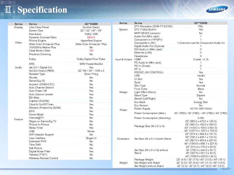
- 4. Ⅱ. Specification -3/23-
- 5. Ⅱ. Specification -3/23-
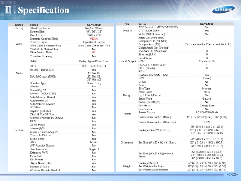
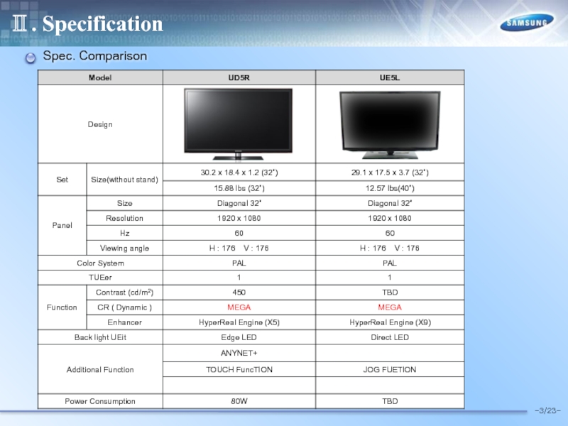
- 6. Ⅱ. Specification -3/23- Spec. Comparison
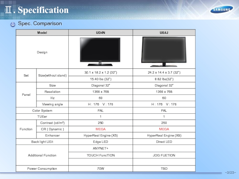
- 7. Ⅱ. Specification -3/23- Spec. Comparison
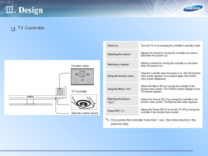
- 8. Ⅲ. Design TV Controller
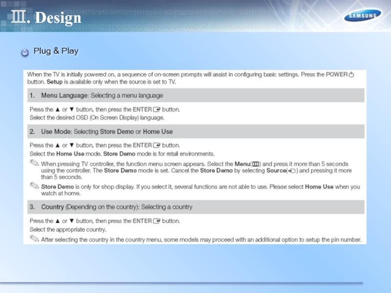
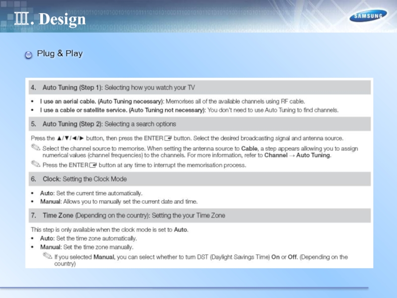
- 9. Ⅲ. Design Plug & Play
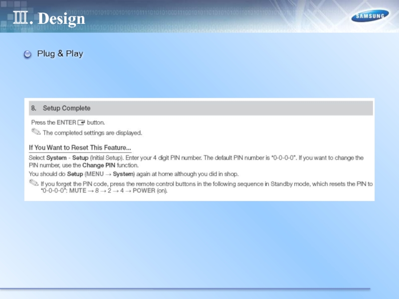
- 10. Ⅲ. Design Plug & Play
- 11. Ⅲ. Design Plug & Play
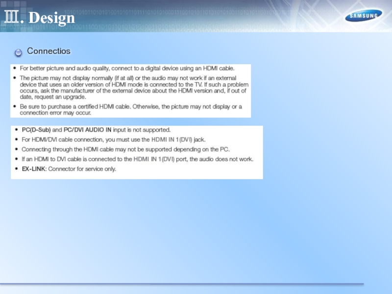
- 12. Ⅲ. Design Connectios
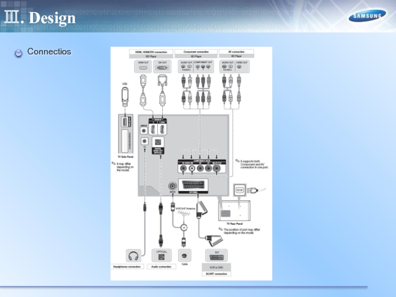
- 13. Ⅲ. Design Connectios
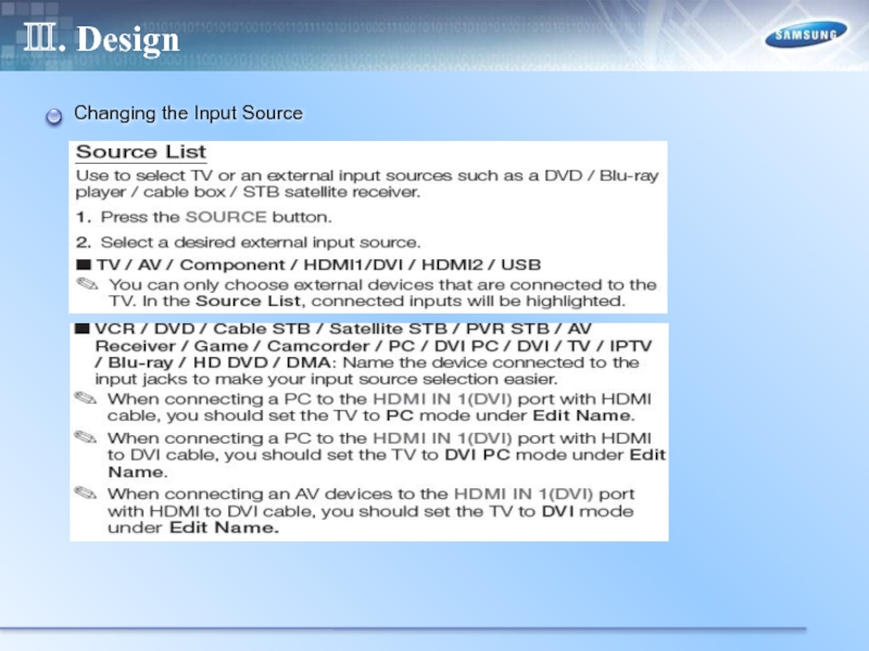
- 14. Ⅲ. Design Changing the Input Source
- 15. Ⅲ. Design Display Modes(HDMI/DVI)
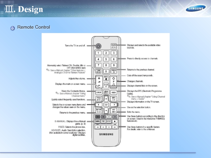
- 16. Ⅲ. Design Remote Control
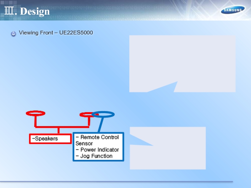
- 17. Ⅲ. Design Viewing Front – UE22ES5000 -Speakers
- 18. Ⅲ. Design Rear – UE22ES5000
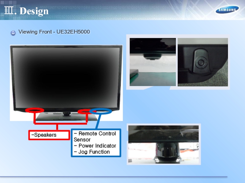
- 19. Ⅲ. Design Viewing Front - UE32EH5000 -Speakers
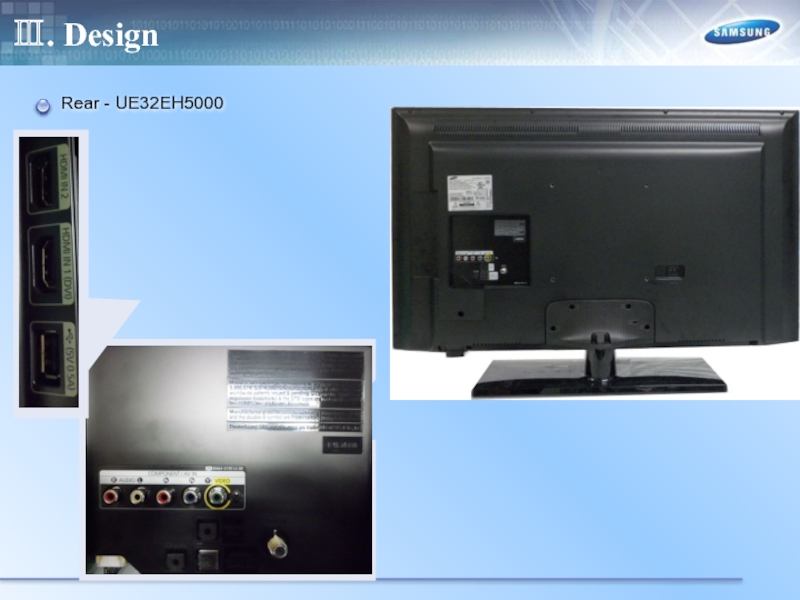
- 20. Ⅲ. Design Rear - UE32EH5000
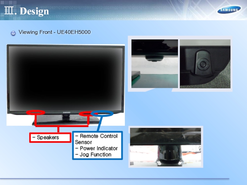
- 21. Ⅲ. Design Viewing Front - UE40EH5000
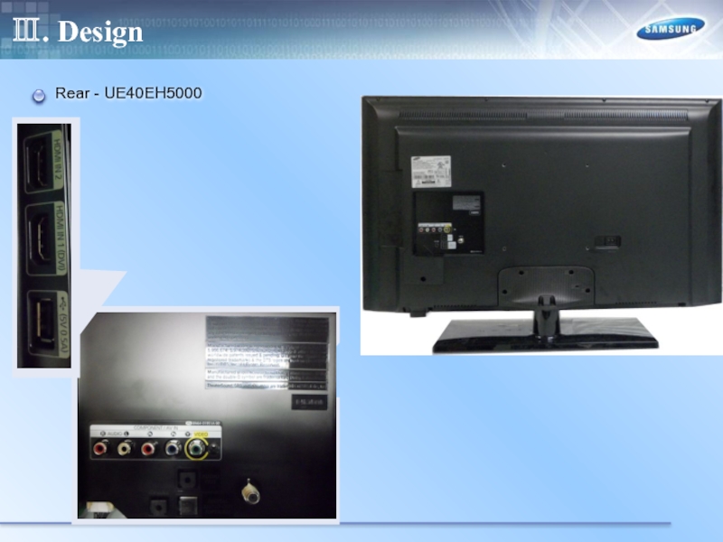
- 22. Ⅲ. Design Rear - UE40EH5000
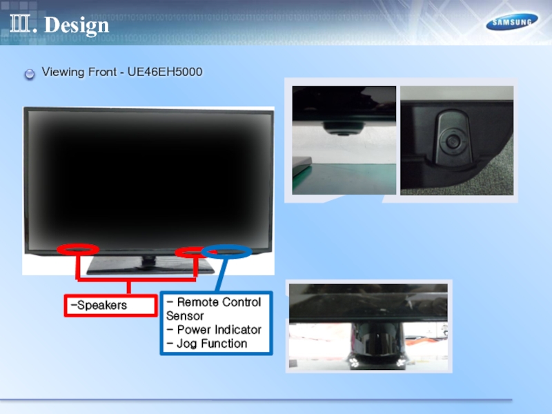
- 23. Ⅲ. Design Viewing Front - UE46EH5000
- 24. Ⅲ. Design Rear - UE46EH5000
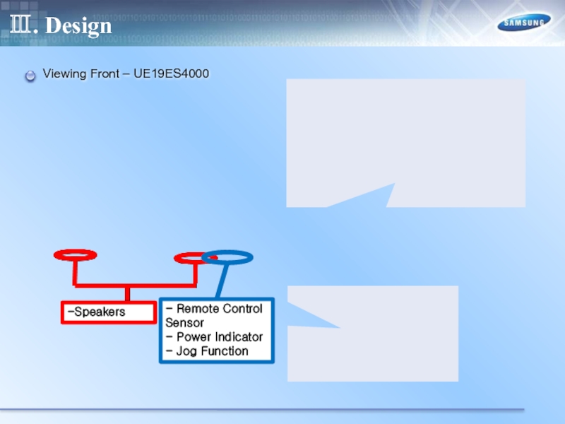
- 25. Ⅲ. Design Viewing Front – UE19ES4000
- 26. Ⅲ. Design Rear – UE19ES4000
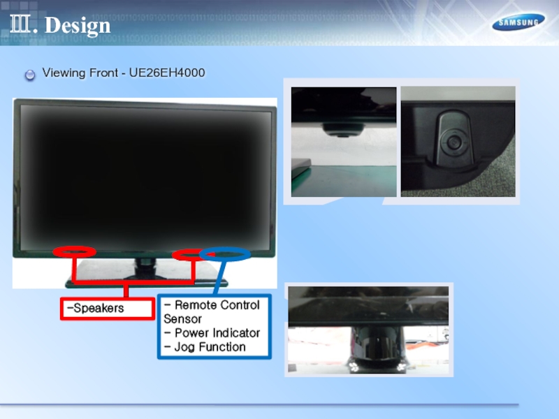
- 27. Ⅲ. Design Viewing Front - UE26EH4000
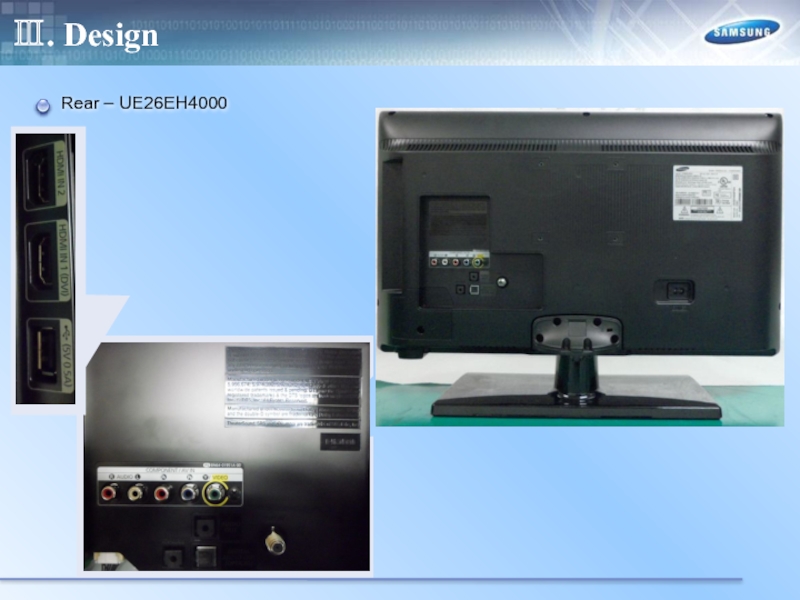
- 28. Ⅲ. Design Rear – UE26EH4000
- 29. Ⅲ. Design Viewing Front - UE32EH4000 -
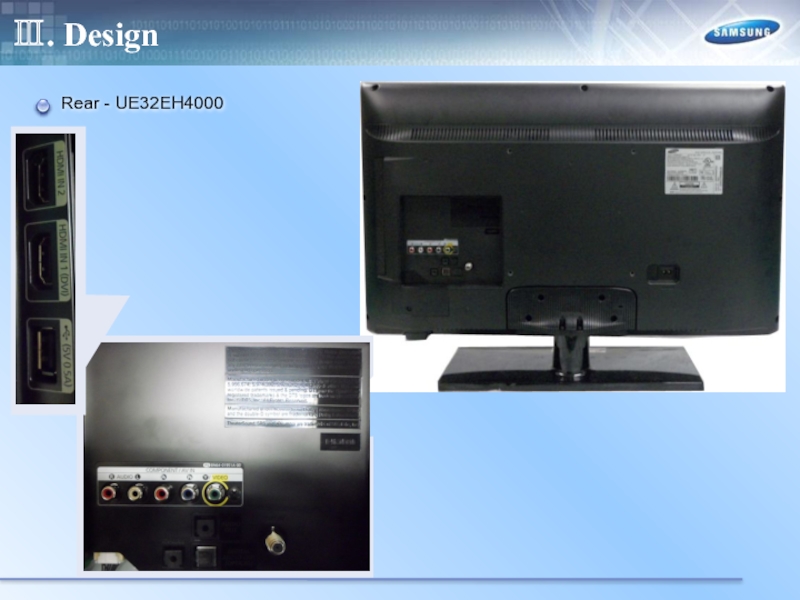
- 30. Ⅲ. Design Rear - UE32EH4000
- 31. Ⅳ. Inner Feature LAY OUT – UE19ES5000
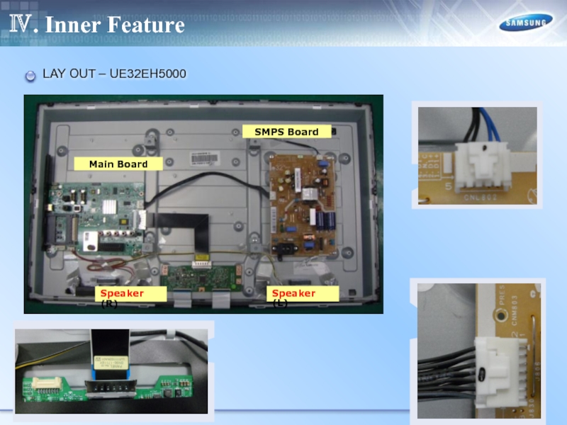
- 32. Ⅳ. Inner Feature LAY OUT – UE32EH5000
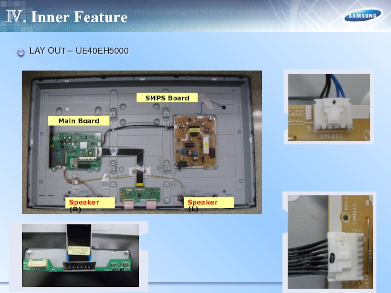
- 33. Ⅳ. Inner Feature LAY OUT – UE40EH5000
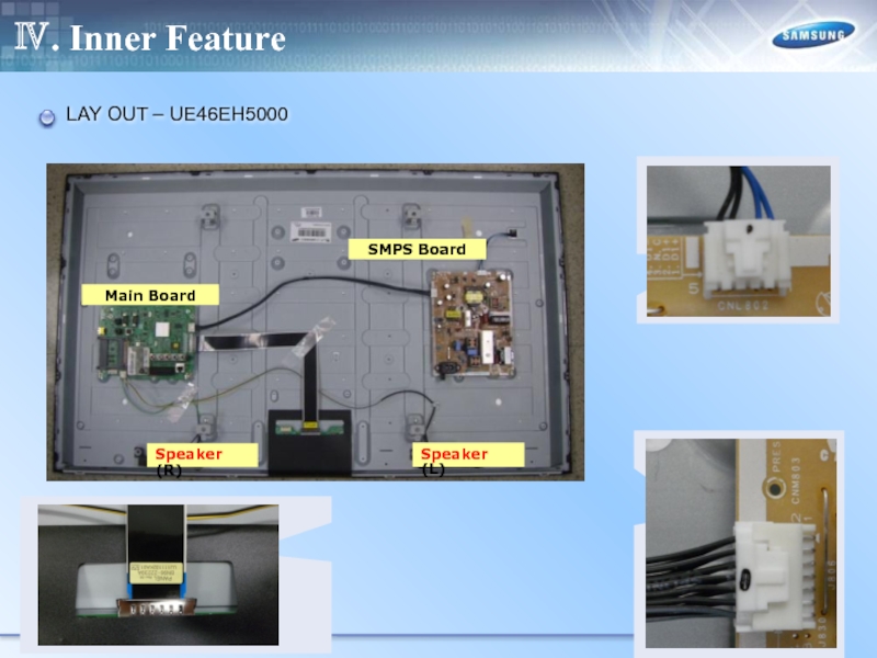
- 34. Ⅳ. Inner Feature LAY OUT – UE46EH5000
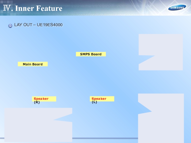
- 35. Ⅳ. Inner Feature LAY OUT – UE19ES4000
- 36. Ⅳ. Inner Feature Main Board SMPS Board
- 37. Main Board SMPS Board Speaker (R) Speaker
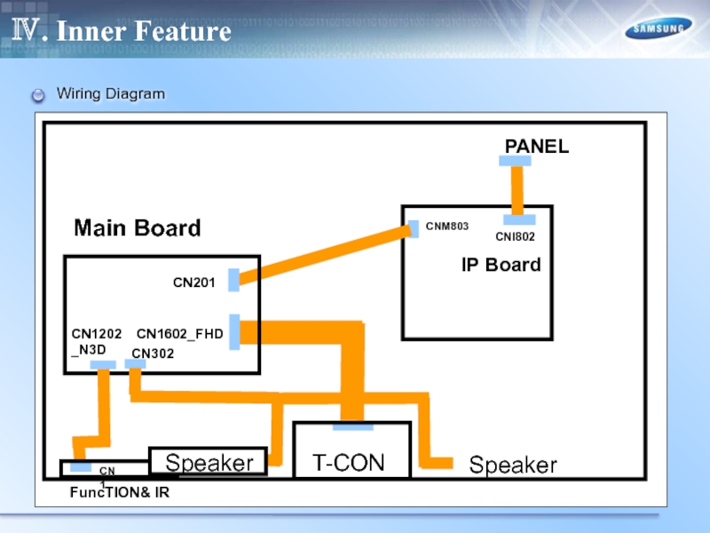
- 38. Ⅳ. Inner Feature Wiring Diagram
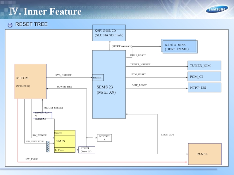
- 39. Ⅳ. Inner Feature RESET TREE
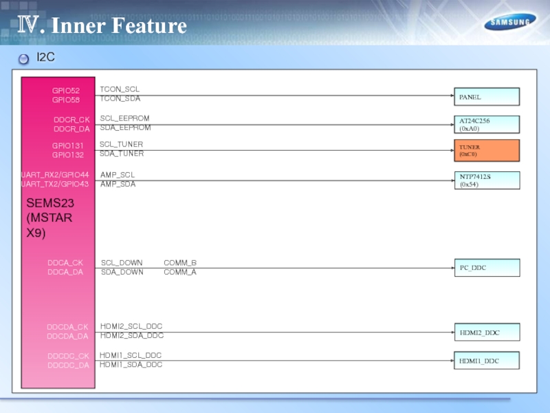
- 40. Ⅳ. Inner Feature I2C SEMS23 (MSTAR
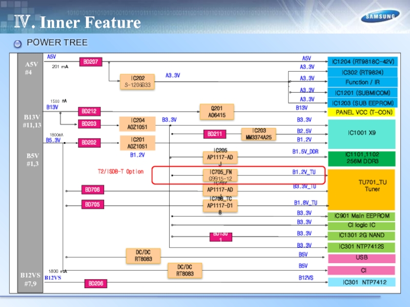
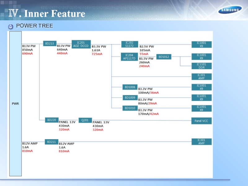
- 41. Ⅳ. Inner Feature POWER TREE
- 42. Ⅳ. Inner Feature POWER TREE
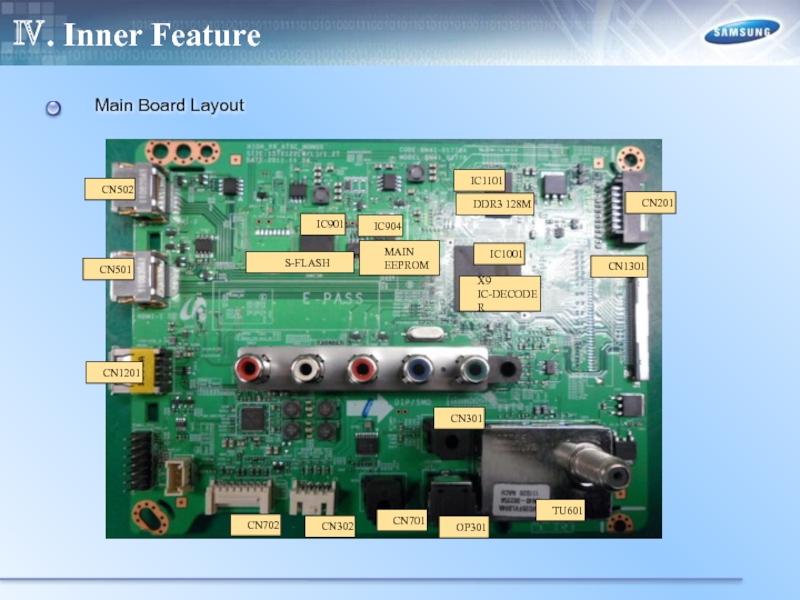
- 43. Ⅳ. Inner Feature Main Board Layout
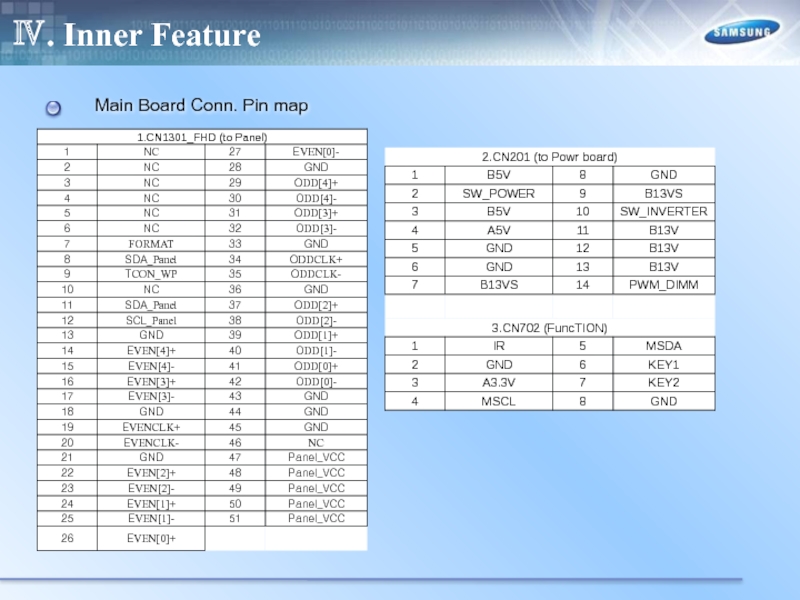
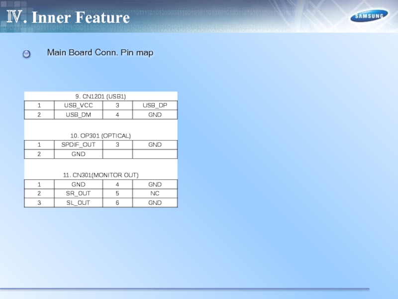
- 44. Ⅳ. Inner Feature Main Board Conn. Pin map
- 45. Ⅳ. Inner Feature Main Board Conn. Pin map
- 46. Ⅳ. Inner Feature Main Board Conn. Pin map
- 47. Ⅳ. Inner Feature Main Board Conn. Pin map
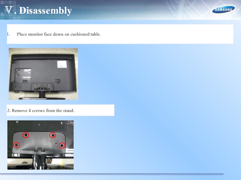
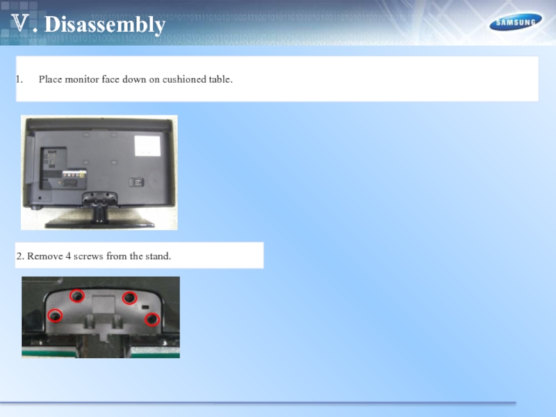
- 48. Ⅴ. Disassembly Place monitor face
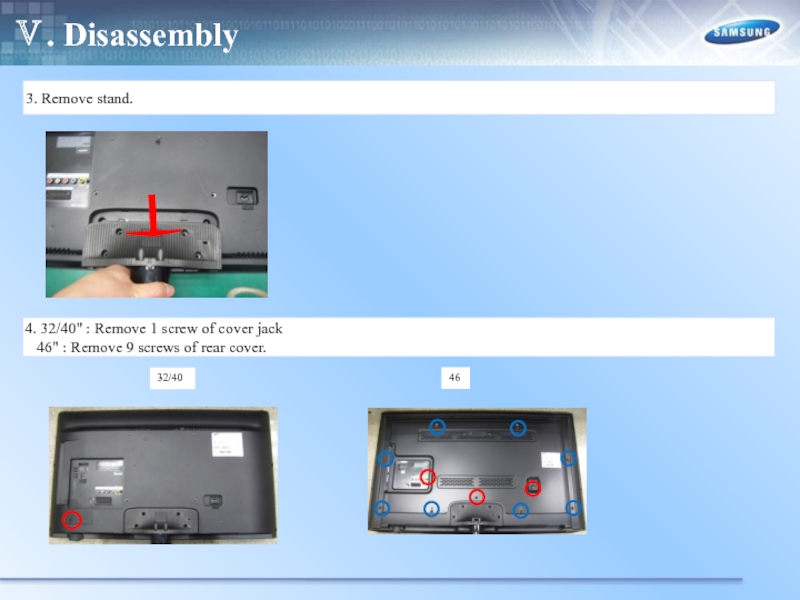
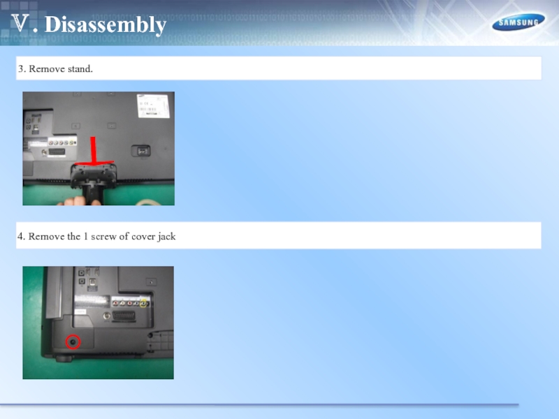
- 49. Ⅴ. Disassembly 3. Remove stand.
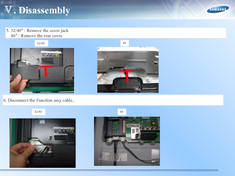
- 50. Ⅴ. Disassembly 5. 32/40" :
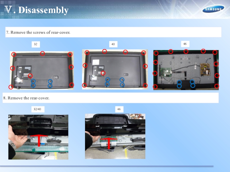
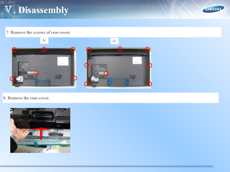
- 51. Ⅴ. Disassembly 7. Remove the
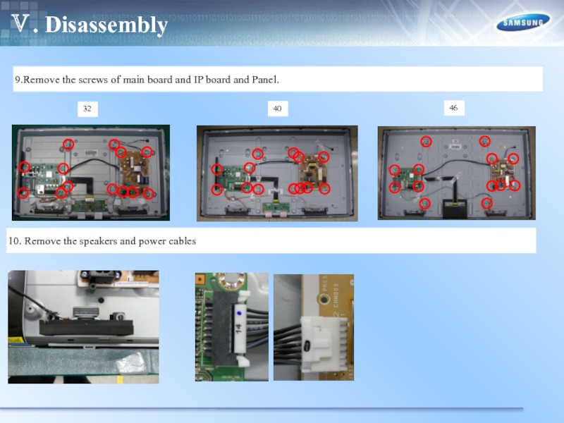
- 52. Ⅴ. Disassembly 9.Remove the screws
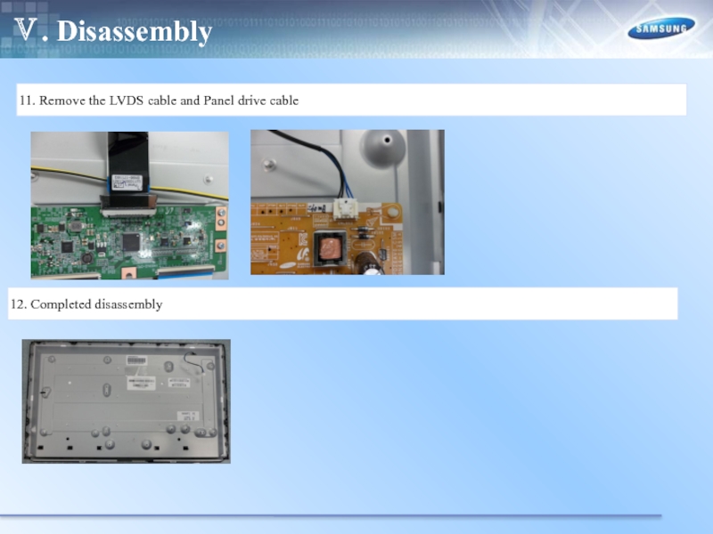
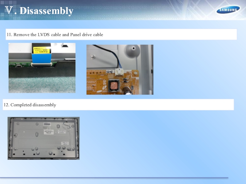
- 53. Ⅴ. Disassembly 11. Remove the
- 54. Ⅴ. Disassembly Place monitor face
- 55. Ⅴ. Disassembly 3. Remove stand. 4. Remove the 1 screw of cover jack
- 56. Ⅴ. Disassembly 5. Remove the cover jack. 6. Disconnect the function assy cable..
- 57. Ⅴ. Disassembly 7. Remove the
- 58. Ⅴ. Disassembly 9.Remove the screws
- 59. Ⅴ. Disassembly 11. Remove the
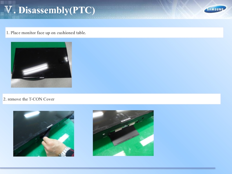
- 60. Ⅴ. Disassembly(PTC) 1. Place monitor
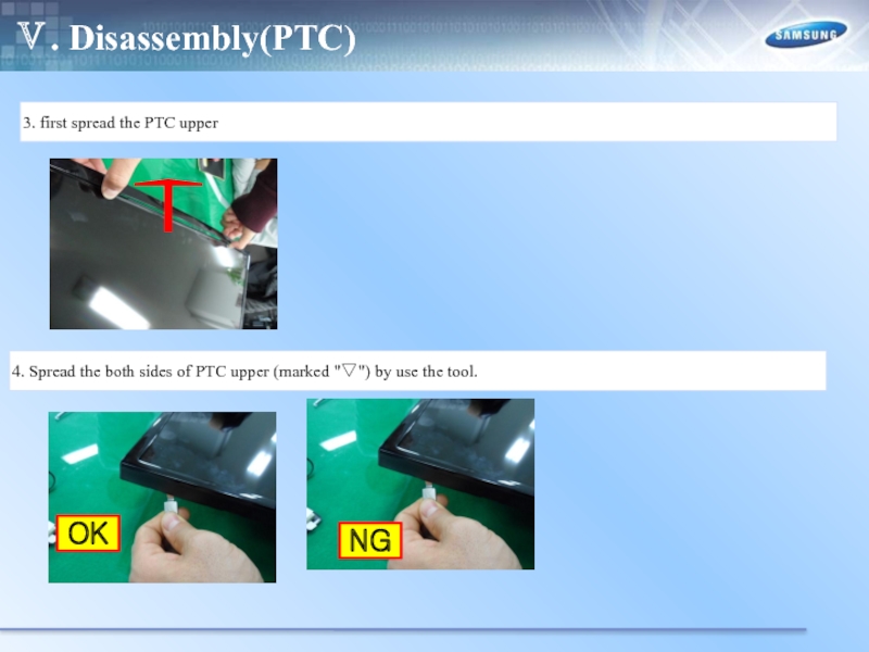
- 61. Ⅴ. Disassembly(PTC) 3. first spread
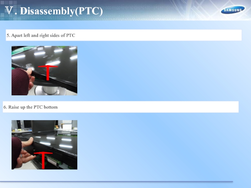
- 62. Ⅴ. Disassembly(PTC) 5. Apart left
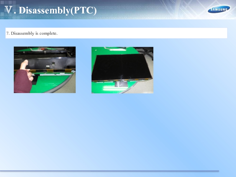
- 63. Ⅴ. Disassembly(PTC) 7. Disassembly is complete.
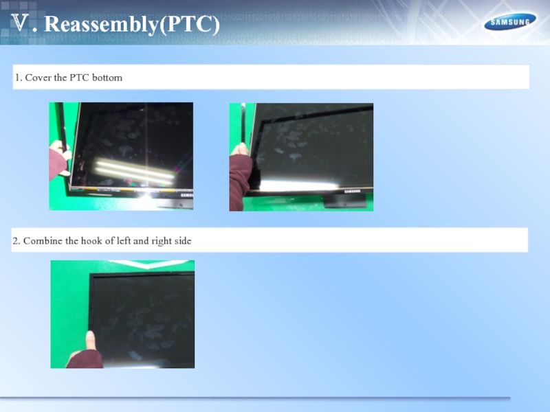
- 64. Ⅴ. Reassembly(PTC) 1. Cover the
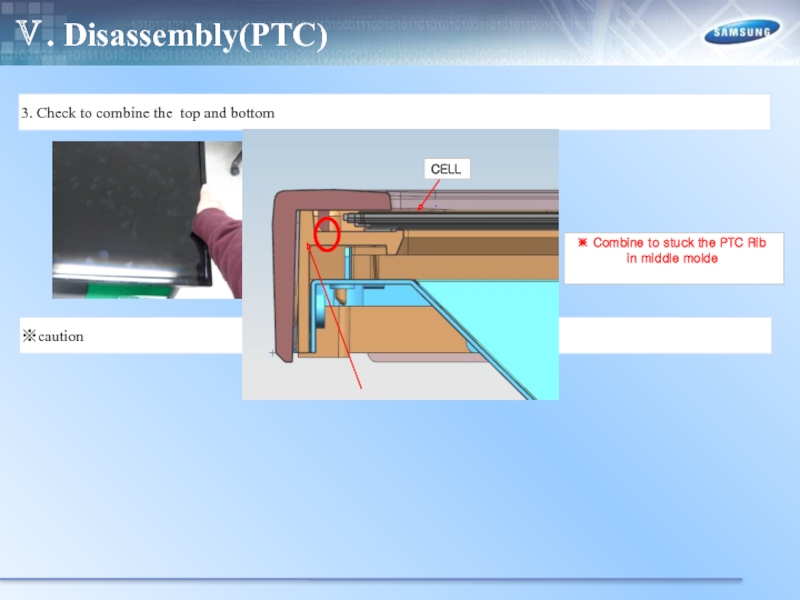
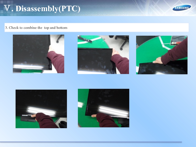
- 65. Ⅴ. Disassembly(PTC) 3. Check to
- 66. Ⅴ. Disassembly(PTC) 3. Check to combine the top and bottom
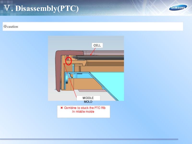
- 67. Ⅴ. Disassembly(PTC) ※caution ※ Combine to stuck the PTC Rib in middle molde
- 68. Ⅴ. Disassembly(PTC) 4. Disassembly is complete.
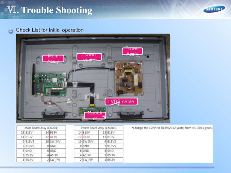
- 69. Ⅵ. Trouble Shooting Check List for Initial operation
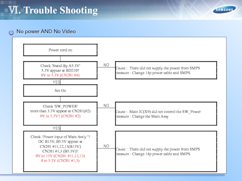
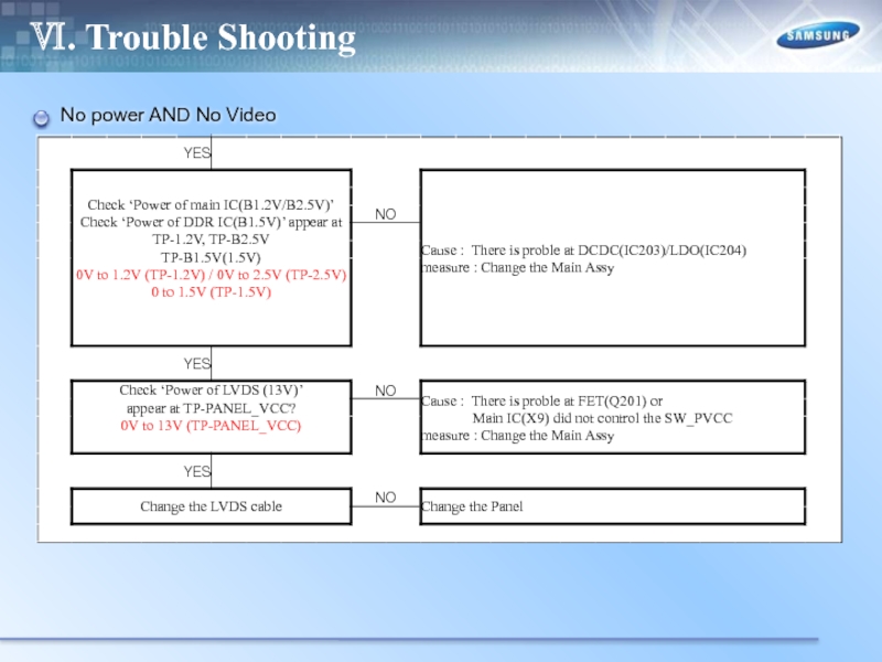
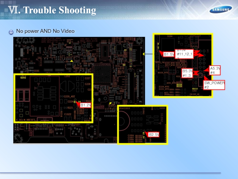
- 70. Ⅵ. Trouble Shooting No power AND No Video
- 71. Ⅵ. Trouble Shooting No power AND No Video
- 72. Ⅵ. Trouble Shooting No power AND No Video
- 73. Ⅵ. Trouble Shooting RS232C code
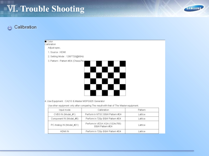
- 74. Ⅵ. Trouble Shooting Calibration
- 75. Ⅵ. Trouble Shooting Calibration
- 76. Ⅵ. Trouble Shooting White Balance
- 77. Ⅵ. Trouble Shooting How to check the SW version
- 78. Ⅵ. Trouble Shooting How to check the SW version
- 79. Ⅵ. Trouble Shooting USB Download
- 80. Ⅵ. Trouble Shooting USB Download
- 81. Ⅵ. Trouble Shooting USB Download
- 82. Ⅵ. Trouble Shooting USB Download
Слайд 1UE22ES5000****
UE**EH50******
UE**EH52******
UE19ES4000W***
UE**EH4000W***
Training Manual
For LED TV UE4,5
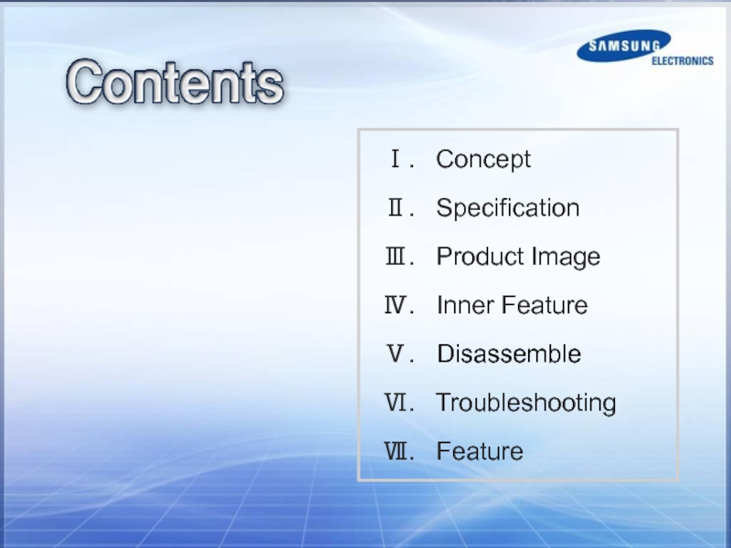
Слайд 2Ⅰ. Concept
Ⅱ. Specification
Ⅲ. Product Image
Ⅳ. Inner
Ⅴ. Disassemble
Ⅵ. Troubleshooting
Ⅶ. Feature
Слайд 3Ⅰ. Product Concept
“The Most Affordable LED TV ever”
Picture Quality
Design : Narrow Bezel
Experience : USB 2.0 Movie
Energy Saving : Low power consumption up to 40% of LCD TV
Слайд 17Ⅲ. Design
Viewing Front – UE22ES5000
-Speakers
- Remote Control Sensor
- Power Indicator
- Jog
Слайд 19Ⅲ. Design
Viewing Front - UE32EH5000
-Speakers
- Remote Control Sensor
- Power Indicator
- Jog
Слайд 21Ⅲ. Design
Viewing Front - UE40EH5000
- Speakers
- Remote Control Sensor
- Power
- Jog Function
Слайд 23Ⅲ. Design
Viewing Front - UE46EH5000
-Speakers
- Remote Control Sensor
- Power Indicator
-
Слайд 25Ⅲ. Design
Viewing Front – UE19ES4000
-Speakers
- Remote Control Sensor
- Power Indicator
-
Слайд 27Ⅲ. Design
Viewing Front - UE26EH4000
-Speakers
- Remote Control Sensor
- Power Indicator
-
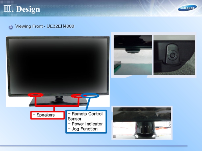
Слайд 29Ⅲ. Design
Viewing Front - UE32EH4000
- Speakers
- Remote Control Sensor
- Power Indicator
-
Слайд 39
Ⅳ. Inner Feature
RESET TREE
SEMS 23
(Mstar X9)
SMPS
Standby
B+ Power
SW_POWER
POWER_DET
SW_PVCC
MICOM
(WT61P802)
SW_INVERTER
RT9824
(Reset IC)
MICOM_nRESET
SYS_HRESET
RT9818_42PV
(Reset IC)
HRESET
NTP7412S
AMP_RESET
LVDS_OUT
PCM_RESET
K4B1G1646E
(DDR3 128MB)
DDR3_RESET
TUNER_NIM
TUNER_NRESET
PCM_CI
NTP7412S
K9F1G08U0D
(SLC NAND Flash)
(RESET command)
Слайд 40
Ⅳ. Inner Feature
I2C
SEMS23
(MSTAR X9)
UART_RX2/GPIO44 UART_TX2/GPIO43
DDCR_CK DDCR_DA
AT24C256
(0xA0)
SCL_EEPROM SDA_EEPROM
TUNER
(0xC0)
SCL_TUNER SDA_TUNER
TCON_SCL
PANEL
NTP7412S
(0x54)
AMP_SCL AMP_SDA
PC_DDC
HDMI2_DDC
HDMI2_SCL_DDC HDMI2_SDA_DDC
HDMI1_DDC
SCL_DOWN SDA_DOWN
HDMI1_SCL_DDC HDMI1_SDA_DDC
GPIO52 GPIO58
GPIO131 GPIO132
DDCA_CK DDCA_DA
DDCDA_CK DDCDA_DA
DDCDC_CK DDCDC_DA
COMM_B COMM_A
Слайд 48Ⅴ. Disassembly
Place monitor face down on cushioned table.
2. Remove 4
Слайд 49Ⅴ. Disassembly
3. Remove stand.
4. 32/40" : Remove 1 screw of
46" : Remove 9 screws of rear cover.
46
32/40
Слайд 50Ⅴ. Disassembly
5. 32/40" : Remove the cover jack
46"
6. Disconnect the Function assy cable..
46
32/40
46
32/40
Слайд 52Ⅴ. Disassembly
9.Remove the screws of main board and IP board
10. Remove the speakers and power cables
40
32
46
Слайд 54Ⅴ. Disassembly
Place monitor face down on cushioned table.
2. Remove 4
Слайд 58Ⅴ. Disassembly
9.Remove the screws of main board and IP board
10. Remove the speakers and power cables.
32
26
Слайд 61Ⅴ. Disassembly(PTC)
3. first spread the PTC upper
4. Spread the both
NG
OK
