- Главная
- Разное
- Дизайн
- Бизнес и предпринимательство
- Аналитика
- Образование
- Развлечения
- Красота и здоровье
- Финансы
- Государство
- Путешествия
- Спорт
- Недвижимость
- Армия
- Графика
- Культурология
- Еда и кулинария
- Лингвистика
- Английский язык
- Астрономия
- Алгебра
- Биология
- География
- Детские презентации
- Информатика
- История
- Литература
- Маркетинг
- Математика
- Медицина
- Менеджмент
- Музыка
- МХК
- Немецкий язык
- ОБЖ
- Обществознание
- Окружающий мир
- Педагогика
- Русский язык
- Технология
- Физика
- Философия
- Химия
- Шаблоны, картинки для презентаций
- Экология
- Экономика
- Юриспруденция
Revision history презентация
Содержание
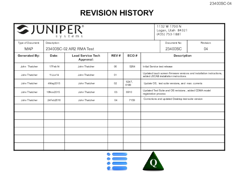
- 1. Revision history
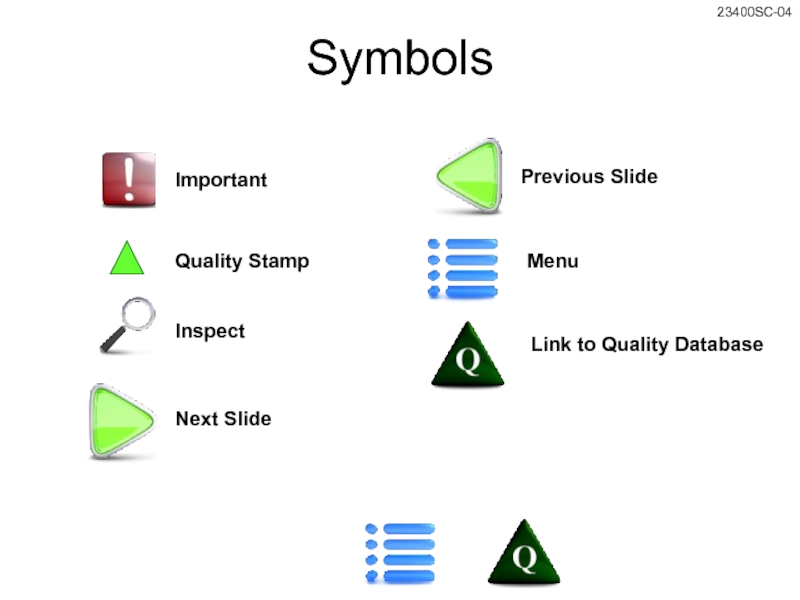
- 2. Symbols Important Inspect Next Slide Previous Slide Menu Link to Quality Database Quality Stamp
- 3. SELECT MODEL TO BE TESTED MENU AR2
- 4. Set Wireless Test Configuration Insert Archer
- 5. Equipment Required – GC Items are
- 6. Equipment Required – GBC Items are
- 7. Equipment Required – Std & Geo
- 8. Equipment Required - GB Items are
- 9. Test Instructions Attach one banana jack
- 10. Test Instructions Attach AR2 emulator to
- 11. Test Instructions Attach AR2 emulator to
- 12. Test Instructions Press the Max button
- 13. Test Instructions Press the Max button
- 14. Test Instructions Attach one banana jack
- 15. Test Instructions Attach AR2 emulator to
- 16. Test Instructions Press the Max button
- 17. Test Instructions Press the Max button
- 18. Test Instructions Attach AR2 emulator to
- 19. Test Suite, OS, Bootloader, & Firmware
- 20. Std, G, & GC Preliminary Inspection
- 21. GB & GBC Preliminary Inspection
- 22. Std, G, & GC - Preliminary
- 23. GC & GCB - Preliminary Inspection,
- 24. Test Instructions If OK is selected
- 25. Test Instructions Perform on new PCBAs prior to burn-in. Install Wi-Fi Calibration
- 26. Test Instructions When the unit restarts,
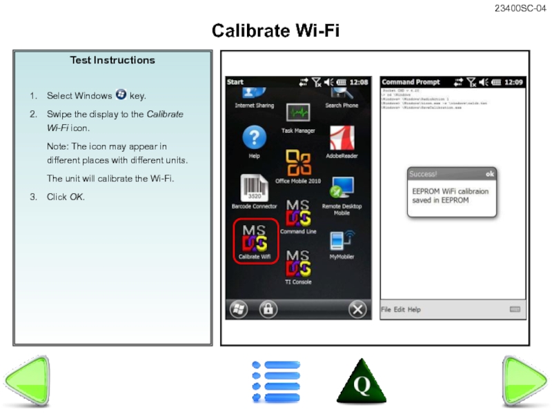
- 27. Test Instructions Calibrate Wi-Fi
- 28. Test Instructions Suspend the UUT. Note:
- 29. Test Instructions Attach battery door using
- 30. Test Instructions Place the unit in
- 31. Test Instructions Insert the Chamber Test
- 32. Assembly Instructions DETERMINATION OF NOMINAL BENCHMARKS IS
- 33. Test Instructions Note: When installing the
- 34. Test Instructions If OK is selected
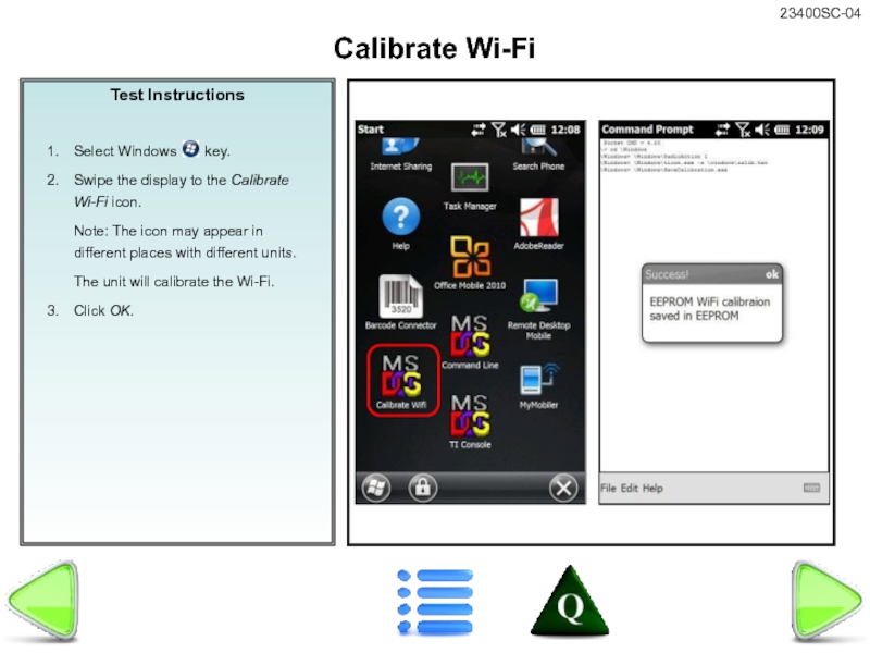
- 35. Test Instructions Calibrate Wi-Fi
- 36. Install your USB Test drive.
- 37. Bar Code Test Press ESC to return
- 38. To Update Serial Number: Install
- 39. Tap on the Speaker button
- 40. Plug the dock’s USB cable
- 41. Tap on the Speaker button
- 42. Perform Wi-Fi configuration & Model
- 43. Tap Save. Wait for “Saved”
- 44. Verify that OS, bootloader, and
- 45. The 306a, 301a, & 300w
- 46. Confirm that cell modem & SIM
- 48. Burn new Serial number and run
- 49. Burn Serial Number on New PCBA -
- 50. If unit fails manual tests, use
- 51. Ref: 12333-** Bubble-Test.TST.doc Perform leak test
- 52. Verify product label is correct.
- 53. Final Inspection Remove all test
- 54. WMDC Connection Test
- 55. Assembly Instructions 1. Copy all files in
- 56. Assembly Instructions This is to have
- 57. Assembly Instructions This is to have
- 58. Assembly Instructions This is to have
- 59. Assembly Instructions This is to have
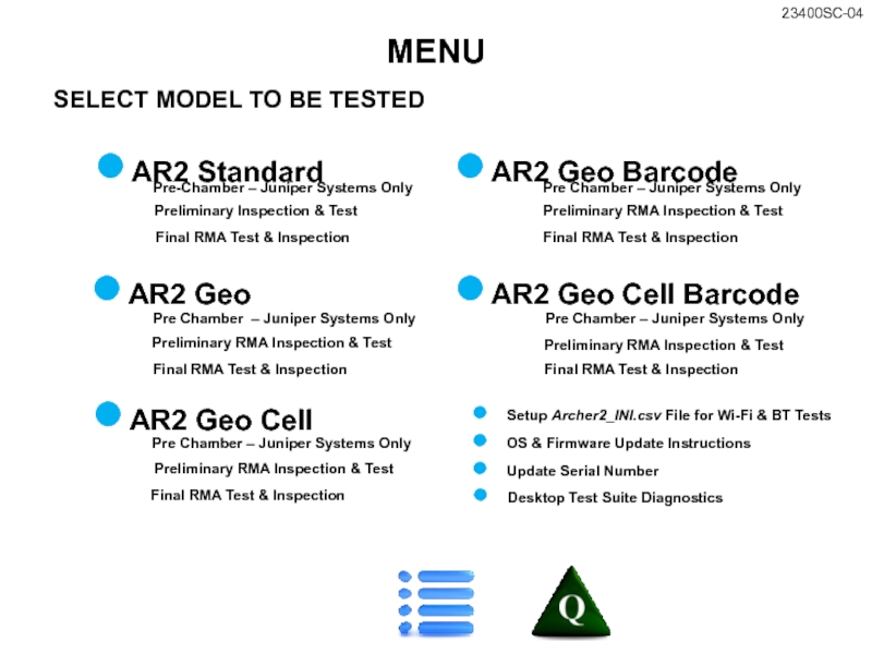
Слайд 3SELECT MODEL TO BE TESTED
MENU
AR2 Standard
AR2 Geo
AR2 Geo Cell
AR2 Geo Cell
AR2 Geo Barcode
Pre-Chamber – Juniper Systems Only
Preliminary Inspection & Test
Pre Chamber – Juniper Systems Only
Preliminary RMA Inspection & Test
Pre Chamber – Juniper Systems Only
Preliminary RMA Inspection & Test
Pre Chamber – Juniper Systems Only
Preliminary RMA Inspection & Test
Pre Chamber – Juniper Systems Only
Preliminary RMA Inspection & Test
Setup Archer2_INI.csv File for Wi-Fi & BT Tests
OS & Firmware Update Instructions
Final RMA Test & Inspection
Final RMA Test & Inspection
Final RMA Test & Inspection
Final RMA Test & Inspection
Final RMA Test & Inspection
Desktop Test Suite Diagnostics
Update Serial Number
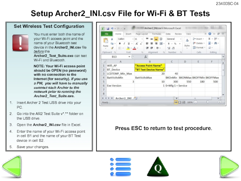
Слайд 4Set Wireless Test Configuration
Insert Archer 2 Test USB drive into your
Go into the AR2 Test Suite v*.** folder on the USB drive.
Open the Archer2_INI.csv file in Excel.
Enter the name of your Wi-Fi access point in cell B1 and the name of your BT Test device in cell B2.
Save your changes.
Setup Archer2_INI.csv File for Wi-Fi & BT Tests
You must enter both the name of your Wi-Fi access point and the name of your Bluetooth test device in the Archer2_INI.csv file before the Archer2_Test_Suite.exe can test Wi-Fi and Bluetooth.
NOTE: Your Wi-Fi access point should be OPEN (no password) with no connection to the Internet (for security). If you use a PW, you will have to manually connect each Archer to the network prior to running the Archer2_Test_Suite.exe.
Press ESC to return to test procedure.
Слайд 5
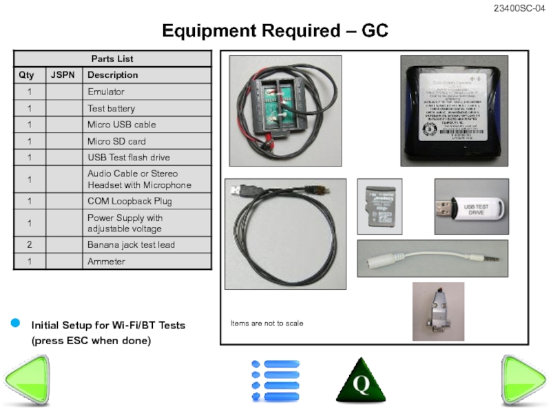
Equipment Required – GC
Items are not to scale
Initial Setup for Wi-Fi/BT
Слайд 6
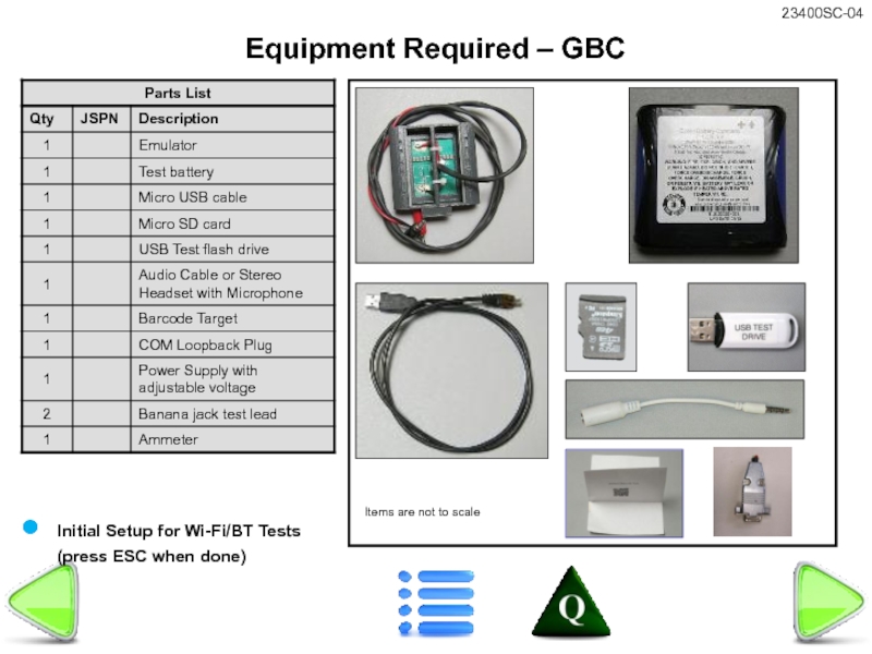
Equipment Required – GBC
Items are not to scale
Initial Setup for Wi-Fi/BT
Слайд 7
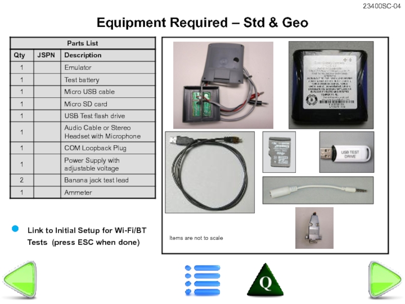
Equipment Required – Std & Geo
Items are not to scale
Link to
Слайд 8
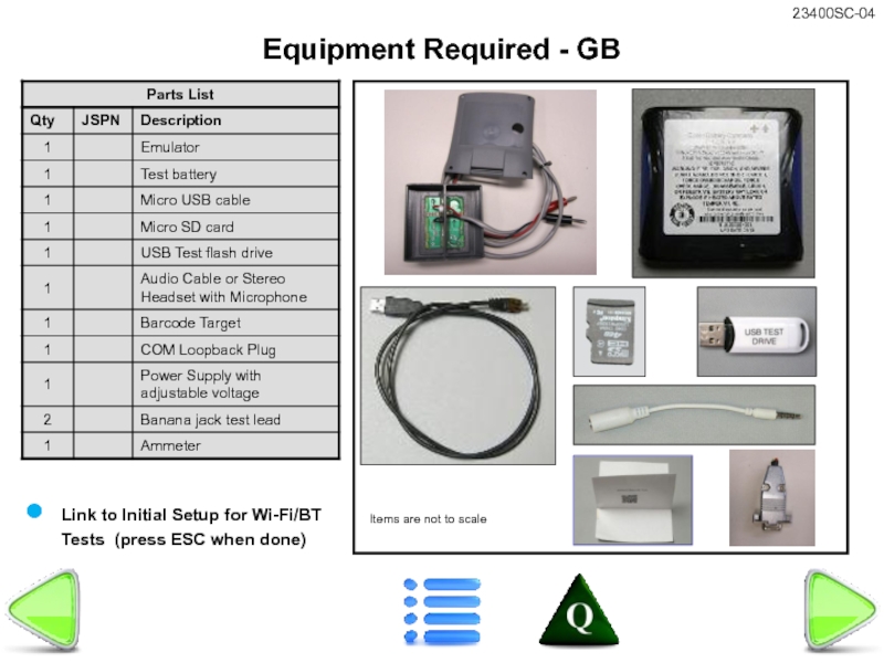
Equipment Required - GB
Items are not to scale
Link to Initial Setup
Слайд 9Test Instructions
Attach one banana jack test lead to the positive (red)
Attach the other end of this lead to the V Ω Cap input of the meter.
Attach one banana jack test lead to the negative (black) terminal on the power supply.
Attach the other end of this lead to the Common input of the meter.
Turn the meter dial to the VDC setting.
Turn on power supply.
Set power supply to 3.65 +/- .5 volts.
Remove the banana jack lead from the power supply positive terminal and meter.
Set up Power Supply for Preliminary Inspection
Слайд 10Test Instructions
Attach AR2 emulator to power supply and ammeter as follows:
Red
Black plug on emulator to 10A input of ammeter
Banana jack test lead from COM input of ammeter to negative terminal of power supply (should still be there from voltage setting)
Set ammeter to the A/mA setting
Remove battery door from Unit Under Test (UUT).
Attach emulator to UUT with the red wire on the emulator UP (toward the top of the handheld).
Secure the emulator with the test door, torqueing two diagonal screws to 2 in/lbs.
Install Battery Emulator – Preliminary Inspection All Models
Слайд 11Test Instructions
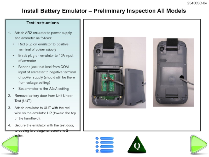
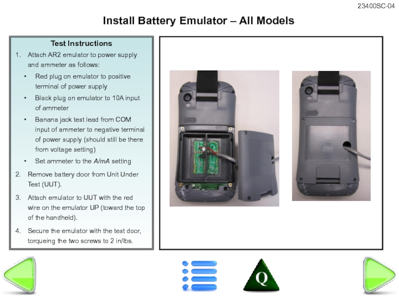
Attach AR2 emulator to power supply and ammeter as follows:
Red
Black plug on emulator to 10A input of ammeter
Banana jack test lead from COM input of ammeter to negative terminal of power supply (should still be there from voltage setting)
Set ammeter to the A/mA setting
Remove battery door from Unit Under Test (UUT).
Attach emulator to UUT with the red wire on the emulator UP (toward the top of the handheld).
Secure the emulator with the test door, torqueing the two screws to 2 in/lbs.
Install Battery Emulator – All Models
Слайд 12Test Instructions
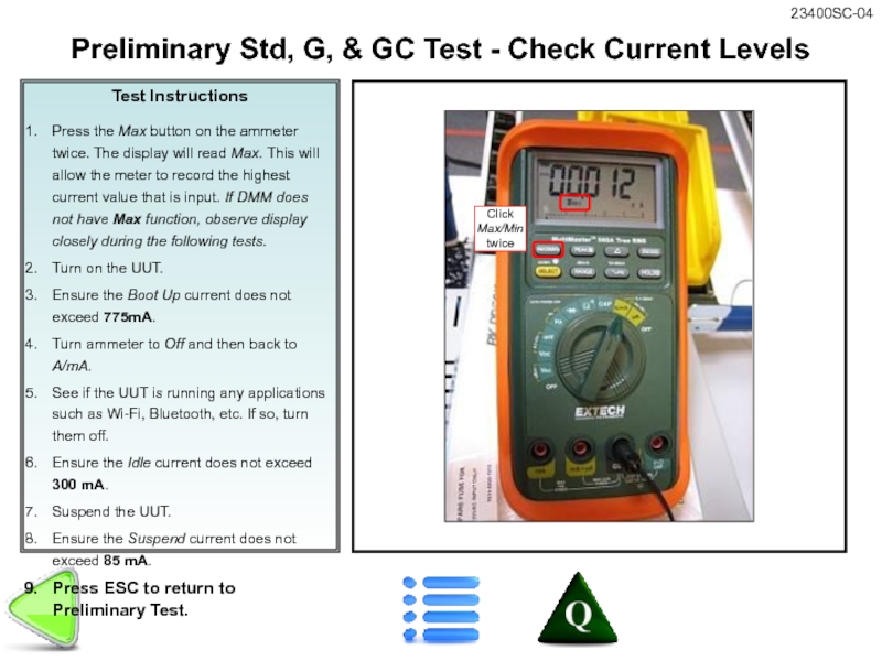
Press the Max button on the ammeter twice. The display
Turn on the UUT.
Ensure the Boot Up current does not exceed 775mA.
Turn ammeter to Off and then back to A/mA.
See if the UUT is running any applications such as Wi-Fi, Bluetooth, etc. If so, turn them off.
Ensure the Idle current does not exceed 300 mA.
Suspend the UUT.
Ensure the Suspend current does not exceed 85 mA.
Press ESC to return to Preliminary Test.
Preliminary Std, G, & GC Test - Check Current Levels
Слайд 13Test Instructions
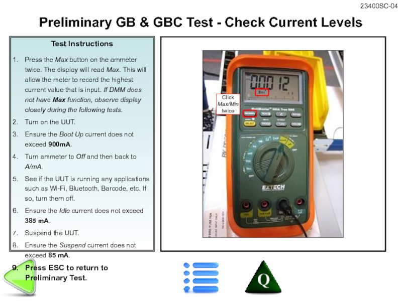
Press the Max button on the ammeter twice. The display
Turn on the UUT.
Ensure the Boot Up current does not exceed 900mA.
Turn ammeter to Off and then back to A/mA.
See if the UUT is running any applications such as Wi-Fi, Bluetooth, Barcode, etc. If so, turn them off.
Ensure the Idle current does not exceed 385 mA.
Suspend the UUT.
Ensure the Suspend current does not exceed 85 mA.
Press ESC to return to Preliminary Test.
Preliminary GB & GBC Test - Check Current Levels
Слайд 14Test Instructions
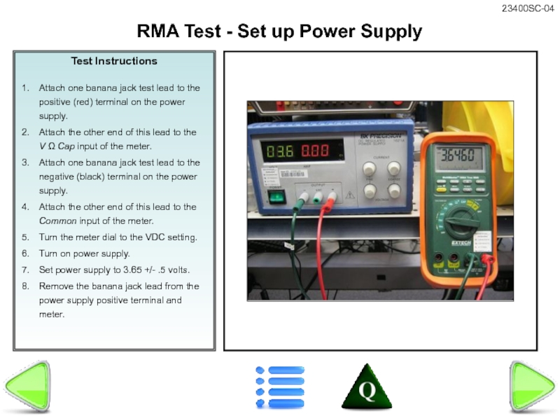
Attach one banana jack test lead to the positive (red)
Attach the other end of this lead to the V Ω Cap input of the meter.
Attach one banana jack test lead to the negative (black) terminal on the power supply.
Attach the other end of this lead to the Common input of the meter.
Turn the meter dial to the VDC setting.
Turn on power supply.
Set power supply to 3.65 +/- .5 volts.
Remove the banana jack lead from the power supply positive terminal and meter.
RMA Test - Set up Power Supply
Слайд 15Test Instructions
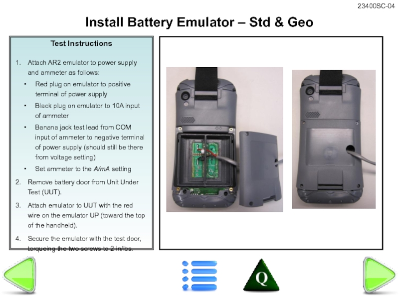
Attach AR2 emulator to power supply and ammeter as follows:
Red
Black plug on emulator to 10A input of ammeter
Banana jack test lead from COM input of ammeter to negative terminal of power supply (should still be there from voltage setting)
Set ammeter to the A/mA setting
Remove battery door from Unit Under Test (UUT).
Attach emulator to UUT with the red wire on the emulator UP (toward the top of the handheld).
Secure the emulator with the test door, torqueing the two screws to 2 in/lbs.
Install Battery Emulator – Std & Geo
Слайд 16Test Instructions
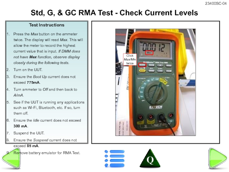
Press the Max button on the ammeter twice. The display
Turn on the UUT.
Ensure the Boot Up current does not exceed 775mA.
Turn ammeter to Off and then back to A/mA.
See if the UUT is running any applications such as Wi-Fi, Bluetooth, etc. If so, turn them off.
Ensure the Idle current does not exceed 300 mA.
Suspend the UUT.
Ensure the Suspend current does not exceed 85 mA.
Remove battery emulator for RMA Test.
Std, G, & GC RMA Test - Check Current Levels
Слайд 17Test Instructions
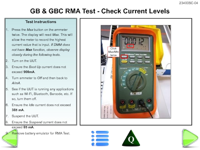
Press the Max button on the ammeter twice. The display
Turn on the UUT.
Ensure the Boot Up current does not exceed 900mA.
Turn ammeter to Off and then back to A/mA.
See if the UUT is running any applications such as Wi-Fi, Bluetooth, Barcode, etc. If so, turn them off.
Ensure the Idle current does not exceed 385 mA.
Suspend the UUT.
Ensure the Suspend current does not exceed 85 mA.
Remove battery emulator for RMA Test.
GB & GBC RMA Test - Check Current Levels
Слайд 18Test Instructions
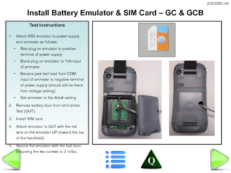
Attach AR2 emulator to power supply and ammeter as follows:
Red
Black plug on emulator to 10A input of ammeter
Banana jack test lead from COM input of ammeter to negative terminal of power supply (should still be there from voltage setting)
Set ammeter to the A/mA setting
Remove battery door from Unit Under Test (UUT).
Install SIM card.
Attach emulator to UUT with the red wire on the emulator UP (toward the top of the handheld).
Secure the emulator with the test door, torqueing the two screws to 2 in/lbs.
Install Battery Emulator & SIM Card – GC & GCB
Слайд 19
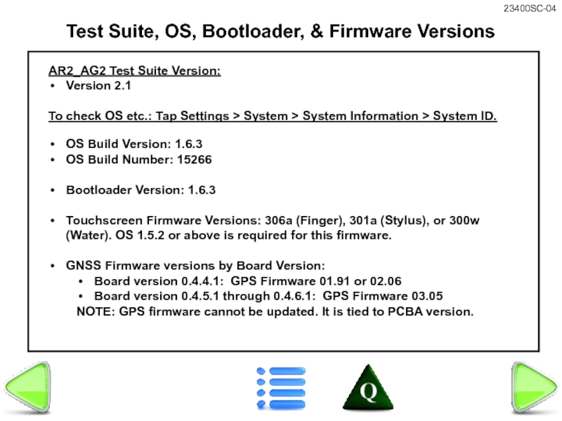
Test Suite, OS, Bootloader, & Firmware Versions
AR2_AG2 Test Suite Version:
Version 2.1
To
OS Build Version: 1.6.3
OS Build Number: 15266
Bootloader Version: 1.6.3
Touchscreen Firmware Versions: 306a (Finger), 301a (Stylus), or 300w (Water). OS 1.5.2 or above is required for this firmware.
GNSS Firmware versions by Board Version:
Board version 0.4.4.1: GPS Firmware 01.91 or 02.06
Board version 0.4.5.1 through 0.4.6.1: GPS Firmware 03.05
NOTE: GPS firmware cannot be updated. It is tied to PCBA version.
Слайд 20
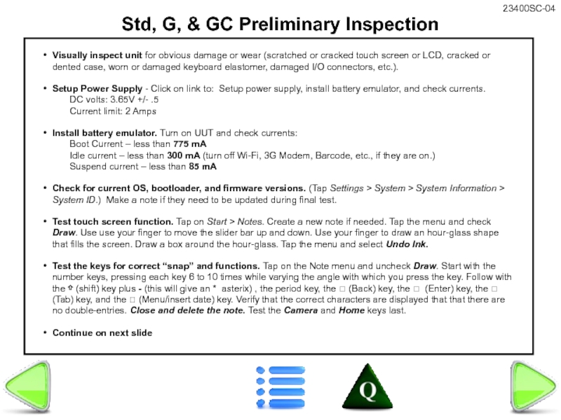
Std, G, & GC Preliminary Inspection
Visually inspect unit for obvious damage
Setup Power Supply - Click on link to: Setup power supply, install battery emulator, and check currents.
DC volts: 3.65V +/- .5
Current limit: 2 Amps
Install battery emulator. Turn on UUT and check currents:
Boot Current – less than 775 mA
Idle current – less than 300 mA (turn off Wi-Fi, 3G Modem, Barcode, etc., if they are on.)
Suspend current – less than 85 mA
Check for current OS, bootloader, and firmware versions. (Tap Settings > System > System Information > System ID.) Make a note if they need to be updated during final test.
Test touch screen function. Tap on Start > Notes. Create a new note if needed. Tap the menu and check Draw. Use use your finger to move the slider bar up and down. Use your finger to draw an hour-glass shape that fills the screen. Draw a box around the hour-glass. Tap the menu and select Undo Ink.
Test the keys for correct “snap” and functions. Tap on the Note menu and uncheck Draw. Start with the number keys, pressing each key 6 to 10 times while varying the angle with which you press the key. Follow with the ⇧ (shift) key plus - (this will give an * asterix) , the period key, the ⮪ (Back) key, the ⮠ (Enter) key, the ⭲ (Tab) key, and the ? (Menu/insert date) key. Verify that the correct characters are displayed that that there are no double-entries. Close and delete the note. Test the Camera and Home keys last.
Continue on next slide
Слайд 21
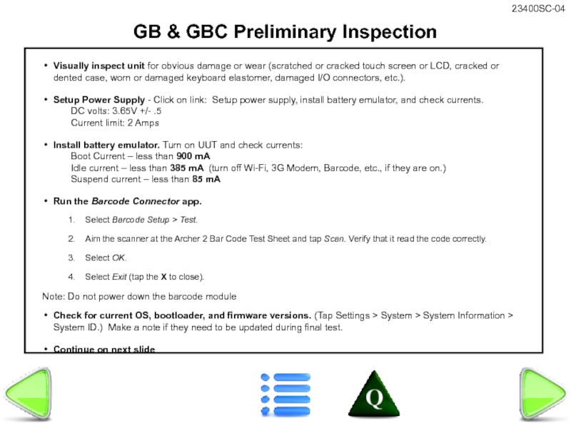
GB & GBC Preliminary Inspection
Visually inspect unit for obvious damage or
Setup Power Supply - Click on link: Setup power supply, install battery emulator, and check currents.
DC volts: 3.65V +/- .5
Current limit: 2 Amps
Install battery emulator. Turn on UUT and check currents:
Boot Current – less than 900 mA
Idle current – less than 385 mA (turn off Wi-Fi, 3G Modem, Barcode, etc., if they are on.)
Suspend current – less than 85 mA
Run the Barcode Connector app.
Select Barcode Setup > Test.
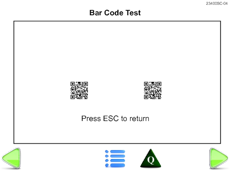
Aim the scanner at the Archer 2 Bar Code Test Sheet and tap Scan. Verify that it read the code correctly.
Select OK.
Select Exit (tap the X to close).
Note: Do not power down the barcode module
Check for current OS, bootloader, and firmware versions. (Tap Settings > System > System Information > System ID.) Make a note if they need to be updated during final test.
Continue on next slide
Слайд 22
Std, G, & GC - Preliminary Inspection, continued
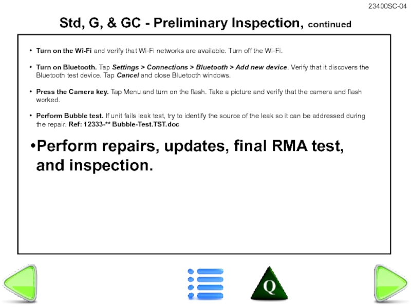
Turn on the Wi-Fi
Turn on Bluetooth. Tap Settings > Connections > Bluetooth > Add new device. Verify that it discovers the Bluetooth test device. Tap Cancel and close Bluetooth windows.
Press the Camera key. Tap Menu and turn on the flash. Take a picture and verify that the camera and flash worked.
Perform Bubble test. If unit fails leak test, try to identify the source of the leak so it can be addressed during the repair. Ref: 12333-** Bubble-Test.TST.doc
Perform repairs, updates, final RMA test, and inspection.
Слайд 23
GC & GCB - Preliminary Inspection, continued
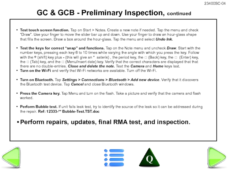
Test touch screen function. Tap
Test the keys for correct “snap” and functions. Tap on the Note menu and uncheck Draw. Start with the number keys, pressing each key 6 to 10 times while varying the angle with which you press the key. Follow with the ⇧ (shift) key plus - (this will give an * asterix) , the period key, the ⮪ (Back) key, the ⮠ (Enter) key, the ⭲ (Tab) key, and the ? (Menu/insert date) key. Verify that the correct characters are displayed that that there are no double-entries. Close and delete the note. Test the Camera and Home keys last.
Turn on the Wi-Fi and verify that Wi-Fi networks are available. Turn off the Wi-Fi.
Turn on Bluetooth. Tap Settings > Connections > Bluetooth > Add new device. Verify that it discovers the Bluetooth test device. Tap Cancel and close Bluetooth windows.
Press the Camera key. Tap Menu and turn on the flash. Take a picture and verify that the camera and flash worked.
Perform Bubble test. If unit fails leak test, try to identify the source of the leak so it can be addressed during the repair. Ref: 12333-** Bubble-Test.TST.doc
Perform repairs, updates, final RMA test, and inspection.
Слайд 24Test Instructions
If OK is selected after the Wi-Fi calibration, the unit
Attach 12 volts external power.
Install Wi-Fi Calibration flash drive.
Select Device and Install.
Do not select OK.
Hold down power key long enough to get the reset menu.
Select Reset.
Remove the flash drive.
Install Wi-Fi Calibration
Слайд 26Test Instructions
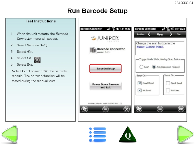
When the unit restarts, the Barcode Connector menu will appear.
Select Barcode Setup.
Select Aim.
Select OK.
Select Exit.
Note: Do not power down the barcode module. The barcode function will be tested during the manual tests.
Run Barcode Setup
Слайд 28Test Instructions
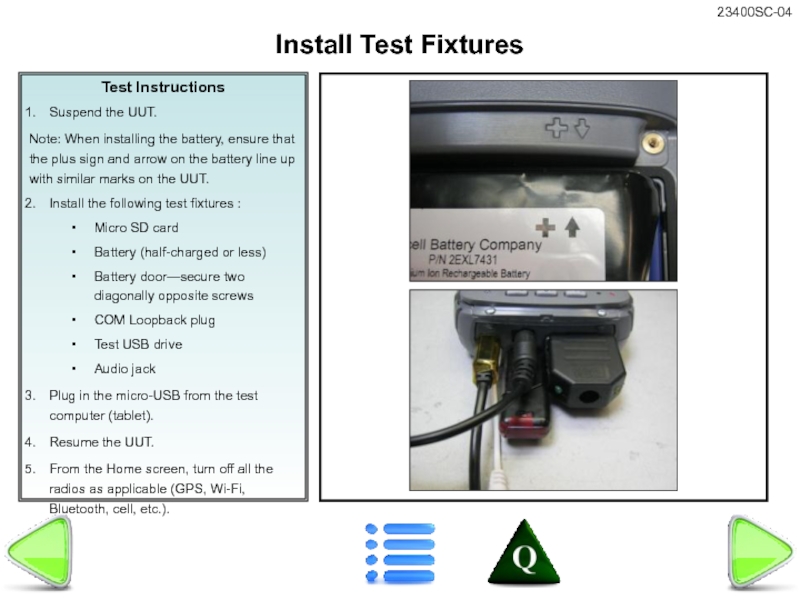
Suspend the UUT.
Note: When installing the battery, ensure that the
Install the following test fixtures :
Micro SD card
Battery (half-charged or less)
Battery door—secure two diagonally opposite screws
COM Loopback plug
Test USB drive
Audio jack
Plug in the micro-USB from the test computer (tablet).
Resume the UUT.
From the Home screen, turn off all the radios as applicable (GPS, Wi-Fi, Bluetooth, cell, etc.).
Install Test Fixtures
Слайд 29Test Instructions
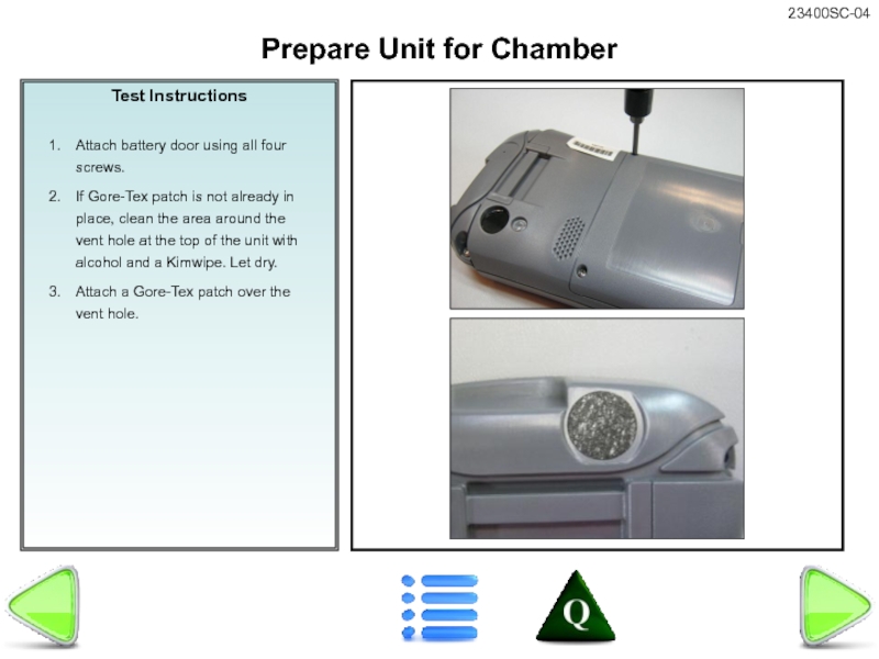
Attach battery door using all four screws.
If Gore-Tex patch is
Attach a Gore-Tex patch over the vent hole.
Prepare Unit for Chamber
Слайд 30Test Instructions
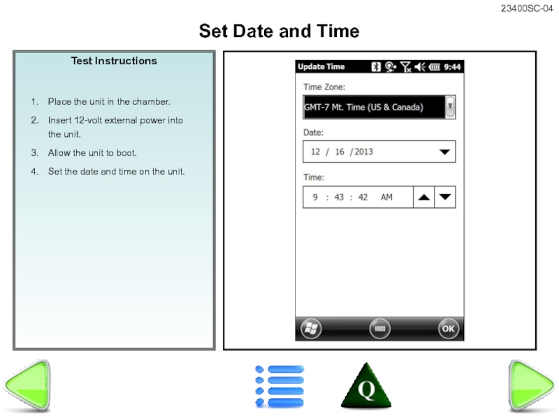
Place the unit in the chamber.
Insert 12-volt external power into
Allow the unit to boot.
Set the date and time on the unit.
Set Date and Time
Слайд 31Test Instructions
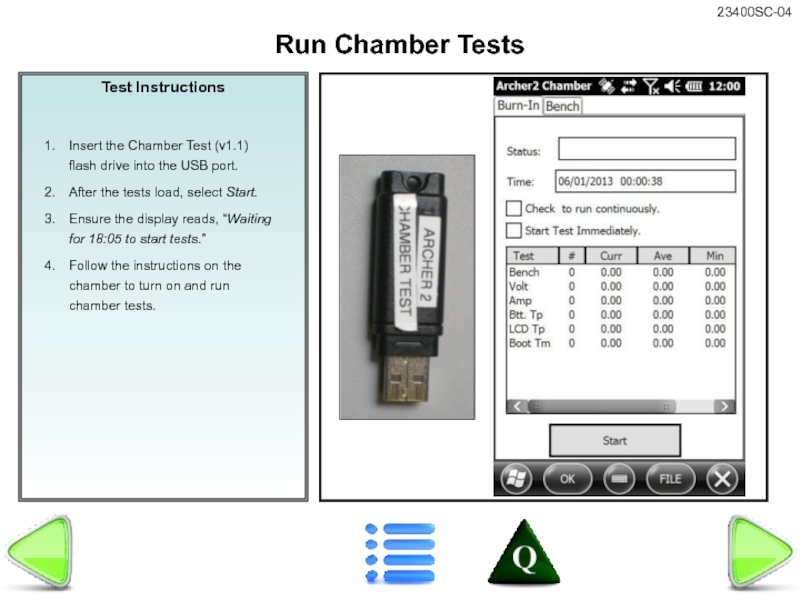
Insert the Chamber Test (v1.1) flash drive into the USB
After the tests load, select Start.
Ensure the display reads, “Waiting for 18:05 to start tests.”
Follow the instructions on the chamber to turn on and run chamber tests.
Run Chamber Tests
Слайд 32Assembly Instructions
DETERMINATION OF NOMINAL BENCHMARKS IS STILL IN PROCESS
Once the unit
Tap on this screen to reveal a dialog box that states that the unit has passed testing.
Remove Unit from Chamber
DETERMINATION OF NOMINAL BENCHMARKS IS STILL IN PROCESS
Слайд 33Test Instructions
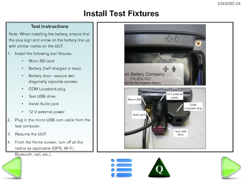
Note: When installing the battery, ensure that the plus sign
Install the following test fixtures:
Micro SD card
Battery (half-charged or less)
Battery door—secure two diagonally opposite screws
COM Loopback plug
Test USB drive
Install Audio jack
12 V external power
Plug in the micro-USB com cable from the test computer.
Resume the UUT.
From the Home screen, turn off all the radios as applicable (GPS, Wi-Fi, Bluetooth, cell, etc.).
Install Test Fixtures
Слайд 34Test Instructions
If OK is selected after the Wi-Fi calibration, the unit
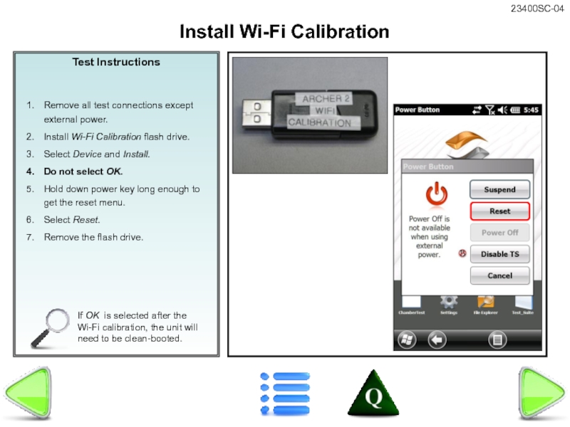
Remove all test connections except external power.
Install Wi-Fi Calibration flash drive.
Select Device and Install.
Do not select OK.
Hold down power key long enough to get the reset menu.
Select Reset.
Remove the flash drive.
Install Wi-Fi Calibration
Слайд 36
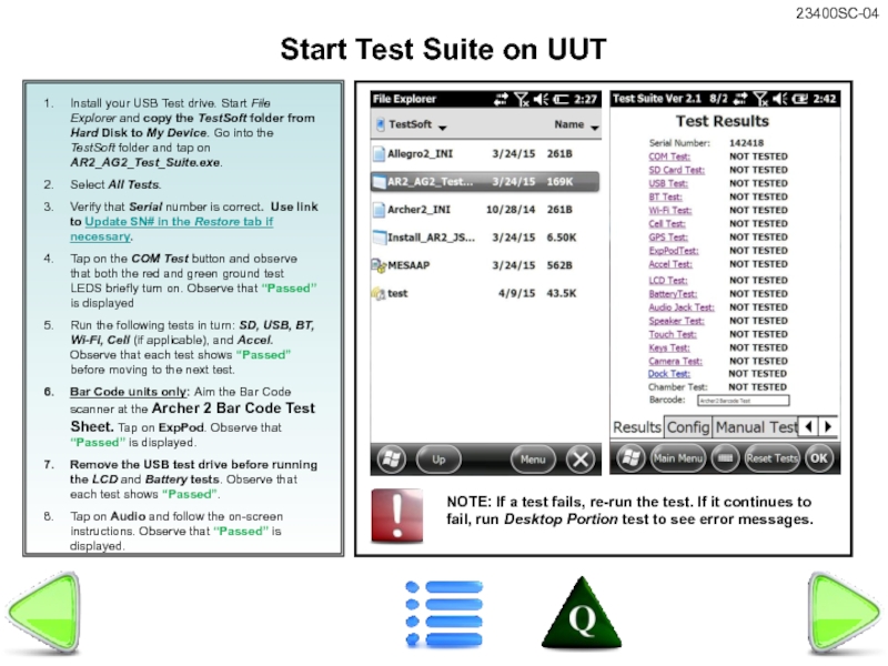
Install your USB Test drive. Start File Explorer and copy the
Select All Tests.
Verify that Serial number is correct. Use link to Update SN# in the Restore tab if necessary.
Tap on the COM Test button and observe that both the red and green ground test LEDS briefly turn on. Observe that “Passed” is displayed
Run the following tests in turn: SD, USB, BT, Wi-Fi, Cell (if applicable), and Accel. Observe that each test shows “Passed” before moving to the next test.
Bar Code units only: Aim the Bar Code scanner at the Archer 2 Bar Code Test Sheet. Tap on ExpPod. Observe that “Passed” is displayed.
Remove the USB test drive before running the LCD and Battery tests. Observe that each test shows “Passed”.
Tap on Audio and follow the on-screen instructions. Observe that “Passed” is displayed.
Start Test Suite on UUT
NOTE: If a test fails, re-run the test. If it continues to fail, run Desktop Portion test to see error messages.
Слайд 38
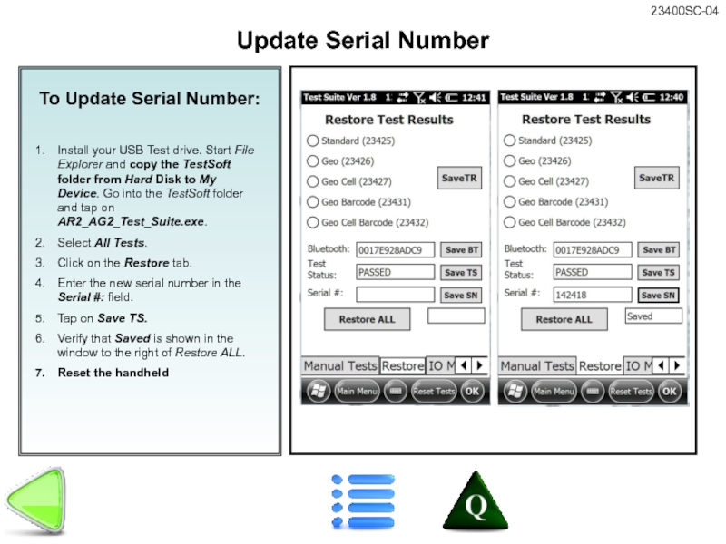
To Update Serial Number:
Install your USB Test drive. Start File Explorer
Select All Tests.
Click on the Restore tab.
Enter the new serial number in the Serial #: field.
Tap on Save TS.
Verify that Saved is shown in the window to the right of Restore ALL.
Reset the handheld
Update Serial Number
Слайд 39
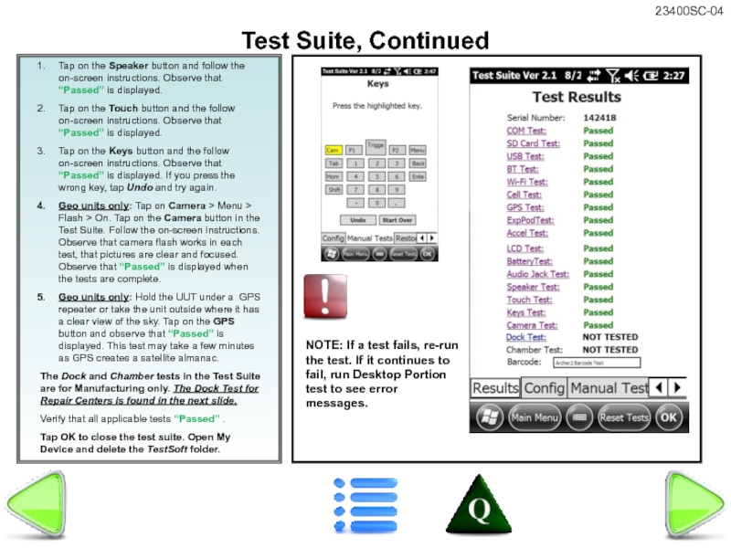
Tap on the Speaker button and follow the on-screen instructions. Observe
Tap on the Touch button and the follow on-screen instructions. Observe that “Passed” is displayed.
Tap on the Keys button and the follow on-screen instructions. Observe that “Passed” is displayed. If you press the wrong key, tap Undo and try again.
Geo units only: Tap on Camera > Menu > Flash > On. Tap on the Camera button in the Test Suite. Follow the on-screen instructions. Observe that camera flash works in each test, that pictures are clear and focused. Observe that “Passed” is displayed when the tests are complete.
Geo units only: Hold the UUT under a GPS repeater or take the unit outside where it has a clear view of the sky. Tap on the GPS button and observe that “Passed” is displayed. This test may take a few minutes as GPS creates a satellite almanac.
The Dock and Chamber tests in the Test Suite are for Manufacturing only. The Dock Test for Repair Centers is found in the next slide.
Verify that all applicable tests “Passed” .
Tap OK to close the test suite. Open My Device and delete the TestSoft folder.
Test Suite, Continued
NOTE: If a test fails, re-run the test. If it continues to fail, run Desktop Portion test to see error messages.
Слайд 40
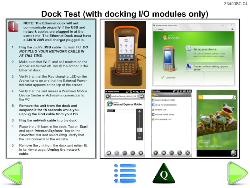
Plug the dock’s USB cable into your PC. DO NOT PLUG
Make sure that Wi-Fi and cell modem on the Archer are turned off. Install the Archer in the Ethernet dock.
Verify that that the Red charging LED on the Archer turns on and that the External Power indicator appears at the top of the screen.
Verify that the unit makes a Windows Mobile Device Center or Activesync connection to the PC.
Remove the unit from the dock and suspend it for 15 seconds while you unplug the USB cable from your PC
Plug the network cable into the dock.
Place the unit back in the dock. Tap on Start and open Internet Explorer. Tap on the Favorites star and select Bing. Verify that the unit connects to the website.
Remove the unit from the dock and return IE to its Home page. Unplug the network cable.
Dock Test (with docking I/O modules only)
NOTE: The Ethernet dock will not communicate properly if the USB and network cables are plugged in at the same time. The Ethernet Dock must have a 24076 20W wall charger plugged in.
Слайд 41
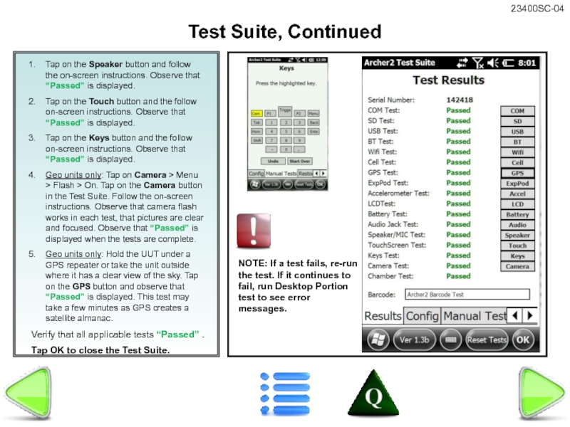
Tap on the Speaker button and follow the on-screen instructions. Observe
Tap on the Touch button and the follow on-screen instructions. Observe that “Passed” is displayed.
Tap on the Keys button and the follow on-screen instructions. Observe that “Passed” is displayed.
Geo units only: Tap on Camera > Menu > Flash > On. Tap on the Camera button in the Test Suite. Follow the on-screen instructions. Observe that camera flash works in each test, that pictures are clear and focused. Observe that “Passed” is displayed when the tests are complete.
Geo units only: Hold the UUT under a GPS repeater or take the unit outside where it has a clear view of the sky. Tap on the GPS button and observe that “Passed” is displayed. This test may take a few minutes as GPS creates a satellite almanac.
Verify that all applicable tests “Passed” .
Tap OK to close the Test Suite.
Test Suite, Continued
NOTE: If a test fails, re-run the test. If it continues to fail, run Desktop Portion test to see error messages.
Слайд 42
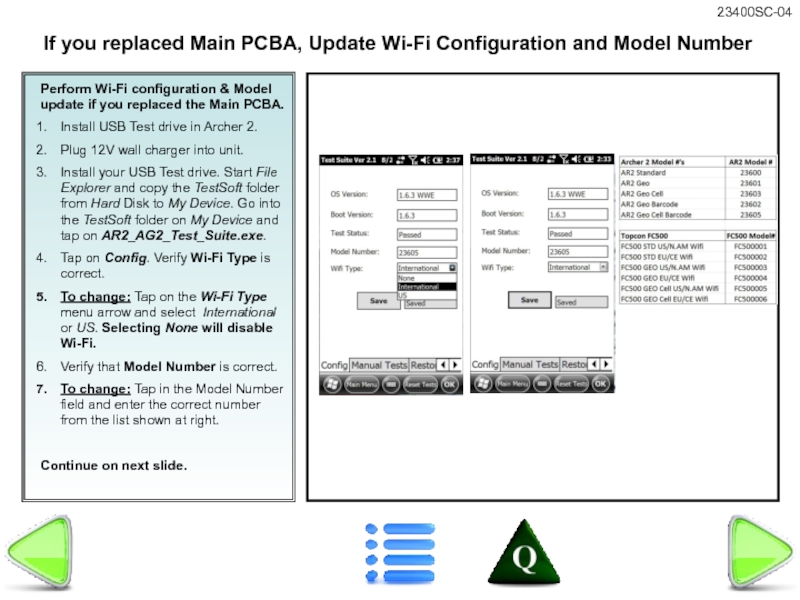
Perform Wi-Fi configuration & Model update if you replaced the Main
Install USB Test drive in Archer 2.
Plug 12V wall charger into unit.
Install your USB Test drive. Start File Explorer and copy the TestSoft folder from Hard Disk to My Device. Go into the TestSoft folder on My Device and tap on AR2_AG2_Test_Suite.exe.
Tap on Config. Verify Wi-Fi Type is correct.
To change: Tap on the Wi-Fi Type menu arrow and select International or US. Selecting None will disable Wi-Fi.
Verify that Model Number is correct.
To change: Tap in the Model Number field and enter the correct number from the list shown at right.
Continue on next slide.
If you replaced Main PCBA, Update Wi-Fi Configuration and Model Number
Слайд 43
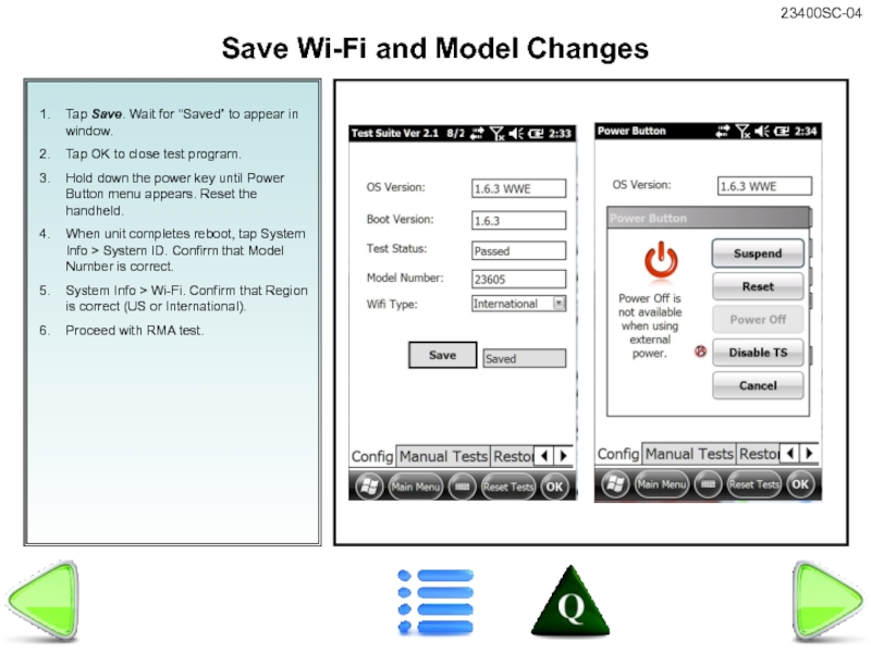
Tap Save. Wait for “Saved” to appear in window.
Tap OK to
Hold down the power key until Power Button menu appears. Reset the handheld.
When unit completes reboot, tap System Info > System ID. Confirm that Model Number is correct.
System Info > Wi-Fi. Confirm that Region is correct (US or International).
Proceed with RMA test.
Save Wi-Fi and Model Changes
Слайд 44
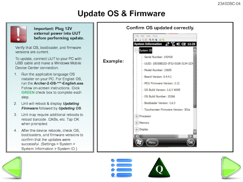
Verify that OS, bootloader, and firmware versions are current.
To update, connect
Run the applicable language OS installer on your PC. For English OS, run the Archer-2-OS-***-English.exe. Follow on-screen instructions. Click GREEN check box to complete each step.
Unit will reboot & display Updating Firmware followed by Updating OS.
Unit may require additional reboots to reload barcode .CABs, etc. Tap OK when prompted.
After the device reboots, check OS, bootloaders, and firmware versions to confirm that the updates were successful. (Settings > System > System Information > System ID.)
Update OS & Firmware
Important: Plug 12V external power into UUT before performing update.
Confirm OS updated correctly.
Example:
Слайд 45
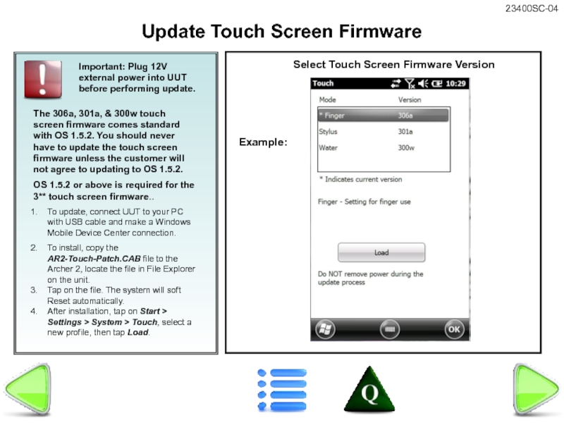
The 306a, 301a, & 300w touch screen firmware comes standard with
OS 1.5.2 or above is required for the 3** touch screen firmware..
To update, connect UUT to your PC with USB cable and make a Windows Mobile Device Center connection.
To install, copy the AR2-Touch-Patch.CAB file to the Archer 2, locate the file in File Explorer on the unit.
Tap on the file. The system will soft Reset automatically.
After installation, tap on Start > Settings > System > Touch, select a new profile, then tap Load.
Update Touch Screen Firmware
Important: Plug 12V external power into UUT before performing update.
Select Touch Screen Firmware Version
Example:
Слайд 46
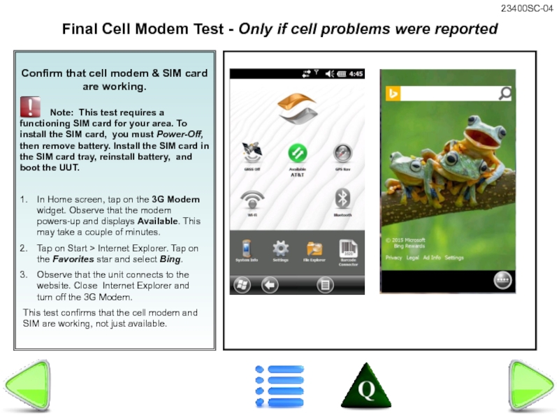
Confirm that cell modem & SIM card are working.
In Home screen, tap on the 3G Modem widget. Observe that the modem powers-up and displays Available. This may take a couple of minutes.
Tap on Start > Internet Explorer. Tap on the Favorites star and select Bing.
Observe that the unit connects to the website. Close Internet Explorer and turn off the 3G Modem.
This test confirms that the cell modem and SIM are working, not just available.
Final Cell Modem Test - Only if cell problems were reported
Слайд 47
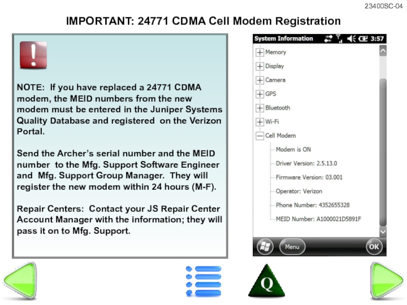
NOTE: If
Send the Archer’s serial number and the MEID number to the Mfg. Support Software Engineer and Mfg. Support Group Manager. They will register the new modem within 24 hours (M-F).
Repair Centers: Contact your JS Repair Center Account Manager with the information; they will pass it on to Mfg. Support.
IMPORTANT: 24771 CDMA Cell Modem Registration
Слайд 48Burn new Serial number and run
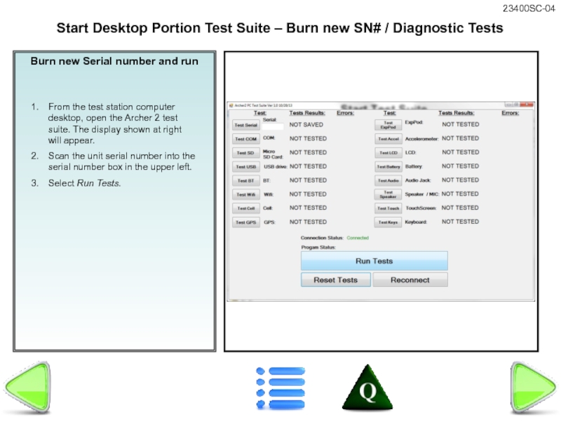
From the test station computer desktop,
Scan the unit serial number into the serial number box in the upper left.
Select Run Tests.
Start Desktop Portion Test Suite – Burn new SN# / Diagnostic Tests
Слайд 49Burn Serial Number on New PCBA -
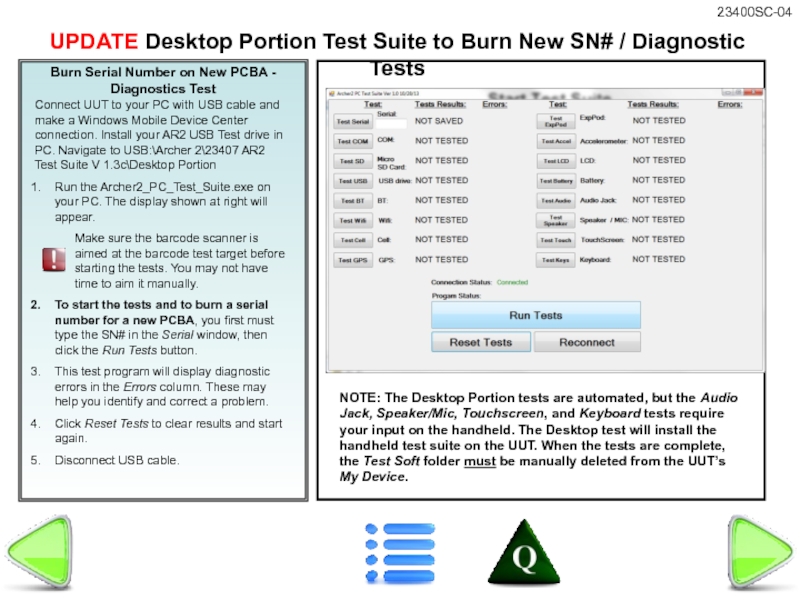
Diagnostics Test
Connect UUT to your
Run the Archer2_PC_Test_Suite.exe on your PC. The display shown at right will appear.
Make sure the barcode scanner is aimed at the barcode test target before starting the tests. You may not have time to aim it manually.
To start the tests and to burn a serial number for a new PCBA, you first must type the SN# in the Serial window, then click the Run Tests button.
This test program will display diagnostic errors in the Errors column. These may help you identify and correct a problem.
Click Reset Tests to clear results and start again.
Disconnect USB cable.
UPDATE Desktop Portion Test Suite to Burn New SN# / Diagnostic Tests
NOTE: The Desktop Portion tests are automated, but the Audio Jack, Speaker/Mic, Touchscreen, and Keyboard tests require your input on the handheld. The Desktop test will install the handheld test suite on the UUT. When the tests are complete, the Test Soft folder must be manually deleted from the UUT’s My Device.
Слайд 50
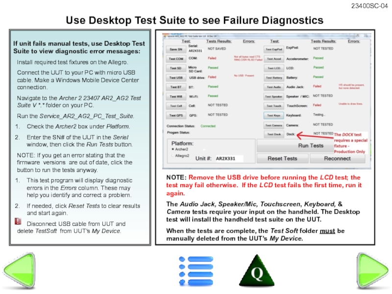
If unit fails manual tests, use Desktop Test Suite to view
Install required test fixtures on the Allegro.
Connect the UUT to your PC with micro USB cable. Make a Windows Mobile Device Center connection.
Navigate to the Archer 2 23407 AR2_AG2 Test Suite V *.* folder on your PC.
Run the Service_AR2_AG2_PC_Test_Suite.
Check the Archer2 box under Platform.
Enter the SN# of the UUT in the Serial window, then click the Run Tests button.
NOTE: If you get an error stating that the firmware versions are out of date, click the button to run the tests anyway.
This test program will display diagnostic errors in the Errors column. These may help you identify and correct a problem.
If needed, click Reset Tests to clear results and start again.
Disconnect USB cable from UUT and delete TestSoft from UUT’s My Device.
Use Desktop Test Suite to see Failure Diagnostics
NOTE: Remove the USB drive before running the LCD test; the test may fail otherwise. If the LCD test fails the first time, run it again.
The Audio Jack, Speaker/Mic, Touchscreen, Keyboard, & Camera tests require your input on the handheld. The Desktop test will install the handheld test suite on the UUT.
When the tests are complete, the Test Soft folder must be manually deleted from the UUT’s My Device.
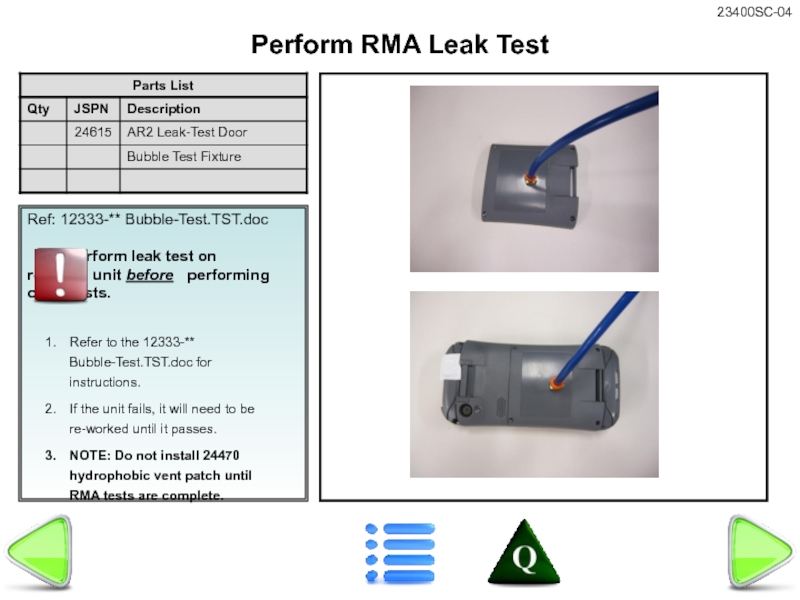
Слайд 51Ref: 12333-** Bubble-Test.TST.doc
Perform leak test on repaired
Refer to the 12333-** Bubble-Test.TST.doc for instructions.
If the unit fails, it will need to be re-worked until it passes.
NOTE: Do not install 24470 hydrophobic vent patch until RMA tests are complete.
Perform RMA Leak Test
Слайд 52
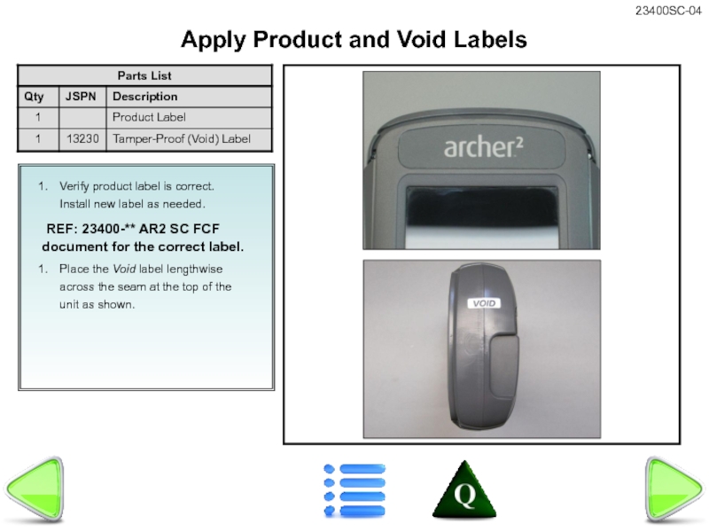
Verify product label is correct. Install new label as needed.
Place the Void label lengthwise across the seam at the top of the unit as shown.
Apply Product and Void Labels
Слайд 53
Final Inspection
Remove all test fixtures. Do not forget test batteries and
Reinstall customer’s cards (if any).
Reinstall customer’s battery and battery door.
Install 24470 Hydrophobic Vent patch.
Install top & bottom bumpers & stylus.
Clean the unit (including bumpers, elastomer, keyboard bezel, and door) with Greased Lightning Multi-Purpose Cleaner, Windex, or mild soap & water.
Inspect unit for any flaws or missing parts, scratches, etc.
Complete RMA paperwork.
Confirm unit is Powered Off.
Confirm that all accessories received with the UUT are in the box before shipping.
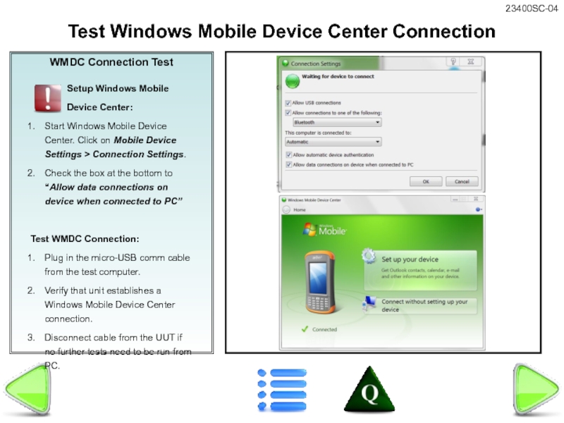
Слайд 54WMDC Connection Test
Setup Windows
Device Center:
Start Windows Mobile Device Center. Click on Mobile Device Settings > Connection Settings.
Check the box at the bottom to “Allow data connections on device when connected to PC”
Test WMDC Connection:
Plug in the micro-USB comm cable from the test computer.
Verify that unit establishes a Windows Mobile Device Center connection.
Disconnect cable from the UUT if no further tests need to be run from PC.
Test Windows Mobile Device Center Connection
Слайд 55Assembly Instructions
1. Copy all files in the FC500 JSCAB Install folder
2. Ensure there are no other files (folders are fine) on the root of the SD card.
3. Install the SD card in the FC-500.
4. Reset the FC-500.
.
FC-500’s ONLY - FC-500 JSCAB Update
If you have replaced the programmed internal microSD card on an FC-500, you must perform the following FC-500.CAB update to install the Topcon splash screens and change the I/O configuration to enable the FC-500 keyboard.
NOTE: A 24618 FC-500 KEYBOARD ASSEMBLY MUST BE INSTALLED BEFORE PERFORMING THIS UPDATE
Слайд 56Assembly Instructions
This is to have the assembler check something after the
Place assembly instructions here.
STEP TITLE
This is to have the assembler check something before the step is done
Слайд 57Assembly Instructions
This is to have the assembler check something after the
Place assembly instructions here.
STEP TITLE
This is to have the assembler check something before the step is done
Слайд 58Assembly Instructions
This is to have the assembler check something after the
Place assembly instructions here.
STEP TITLE
This is to have the assembler check something before the step is done
Слайд 59Assembly Instructions
This is to have the assembler check something after the
Place assembly instructions here.
STEP TITLE
This is to have the assembler check something before the step is done
