Removing 6634 UEPP презентация

Remove the LCD monitor harnesses 4. Disconnect the harnesses, you may leave the video cable connected USB to Touch Screen Light Sensor DC Power Video

Слайд 1Removing 6634 UEPP
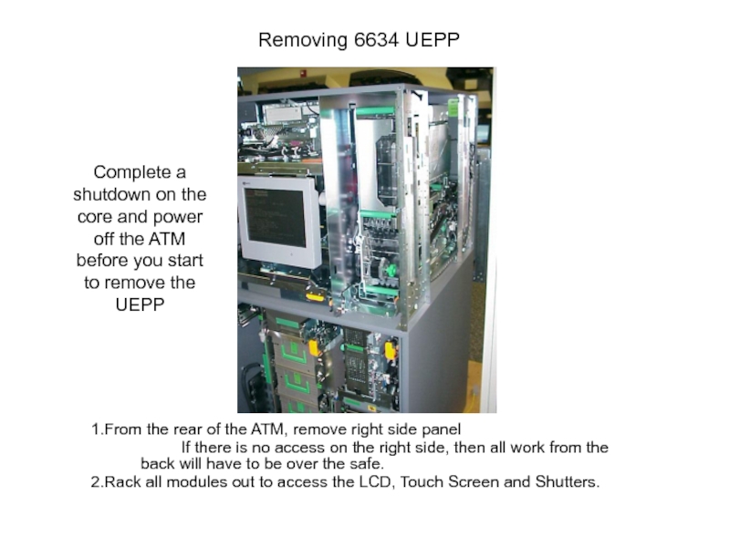
From the rear of the ATM, remove right side

panel
If there is no access on the right side, then all work from the back will have to be over the safe.
Rack all modules out to access the LCD, Touch Screen and Shutters.

Complete a shutdown on the core and power off the ATM before you start to remove the UEPP

Слайд 2Remove the LCD monitor harnesses
4. Disconnect the harnesses, you may leave

the video cable connected


USB to Touch Screen

Light Sensor
DC Power

Video


Слайд 3Remove the LCD Monitor
5. Remove shipping screws, if they are still

present.
6. To disengage the plungers and keep them out, pull plunger out and rotate it 90 degrees
7. Pull the handle upwards and back, place LCD in the area of the Statement printer module. Remember the video harness is still connected.

Handle

Plungers

If the shipping screws are present
There would be one above each Plunger


Plunger


Слайд 4Note the monitor is mounted by two pins on each side.


Plunger


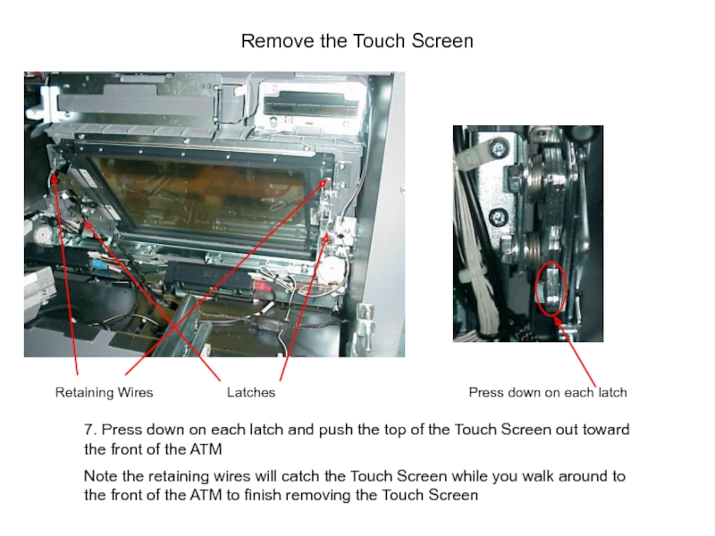
Слайд 5Remove the Touch Screen
Latches
Press down on each latch

7. Press down on

each latch and push the top of the Touch Screen out toward the front of the ATM
Note the retaining wires will catch the Touch Screen while you walk around to the front of the ATM to finish removing the Touch Screen

Retaining Wires


Слайд 6Finish Removing the Touch Screen
8. From the front of the ATM

remove the retaining wire loops off the studs and place the Touch Screen in a safe place


Слайд 7Remove the shutters
9. Disconnect the USB and power harnesses from the

shutters
10. Remove the two screws for each shutter
11. From the view in the picture, remove the right shutter first. Pull up to remove the shutter from the studs. See next page for additional views.


Слайд 8Front view of a shutter
Stud Screws


Слайд 9Remove the keyboard support plate
Note: The picture was taken with the

dispenser shutter still in the ATM. Please remove it first.

12. Remove screw and slide the keyboard support plate back and remove it from the ATM. The keyboard will drop down.
13. Slide keyboard back and out of the ATM, disconnect the harnesses on the keyboard. See next page for additional details.

Screw


Слайд 10Viewed from the front of the ATM
14. Reverse order, for assembly

of components

Keyboard Support Plate

Keyboard slid back


Обратная связь

Если не удалось найти и скачать презентацию, Вы можете заказать его на нашем сайте. Мы постараемся найти нужный Вам материал и отправим по электронной почте. Не стесняйтесь обращаться к нам, если у вас возникли вопросы или пожелания:

Email: Нажмите что бы посмотреть 

Что такое ThePresentation.ru?

Это сайт презентаций, докладов, проектов, шаблонов в формате PowerPoint. Мы помогаем школьникам, студентам, учителям, преподавателям хранить и обмениваться учебными материалами с другими пользователями.


Для правообладателей

Яндекс.Метрика