process technician uses are the following:
Block flow diagram
Process flow diagram
Piping and instrumentation diagram
A block flow diagram (BFD) shows the flow scheme in a simple sequential block form. Not all, but most block flow diagrams show flow from left to right and tend not to cross over lines any more than necessary.
A process flow diagram (PFD) pictorially describe the actual, including the major process equipment, and may provide process variable as well as heat and material balance information. This is one of the first documents developed when initiating tye design of a new plant. The material balance is used in all further flow calculations including main process pumps and compressors, vessels, etc.
A piping and instrumentation diagram (PID) is similar to a PFD but contains no process information but much more detail including instrumentation and the entire control system. These drawings provide the basic mechanical design details and operating philosophy for the plant.
- Главная
- Разное
- Дизайн
- Бизнес и предпринимательство
- Аналитика
- Образование
- Развлечения
- Красота и здоровье
- Финансы
- Государство
- Путешествия
- Спорт
- Недвижимость
- Армия
- Графика
- Культурология
- Еда и кулинария
- Лингвистика
- Английский язык
- Астрономия
- Алгебра
- Биология
- География
- Детские презентации
- Информатика
- История
- Литература
- Маркетинг
- Математика
- Медицина
- Менеджмент
- Музыка
- МХК
- Немецкий язык
- ОБЖ
- Обществознание
- Окружающий мир
- Педагогика
- Русский язык
- Технология
- Физика
- Философия
- Химия
- Шаблоны, картинки для презентаций
- Экология
- Экономика
- Юриспруденция
Process diagram and instrument sketching презентация
Содержание
- 2. Introduction to the Process Diagrams The three
- 3. Block flow diagram (BFD)
- 4. Process flow diagram (PFD)
- 5. Piping and instrumentation diagram (PID)
- 6. All PFDs and P&IDs should have
- 7. ISA Instrument Tag Number An instrument tag
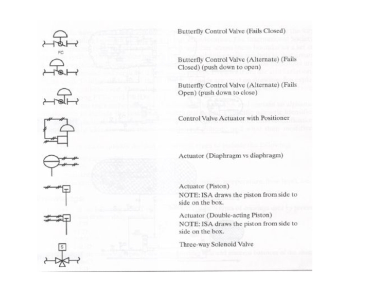
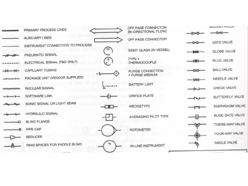
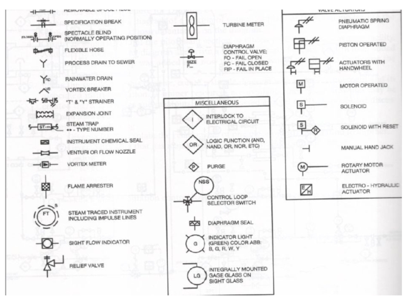
- 10. Basic equipment symbols
- 11. Standard Line symbols
- 12. SYMBOLS In a P&ID, a circle represents
- 13. A hexagon represents computer functions, such as

")
")
")
Слайд 6
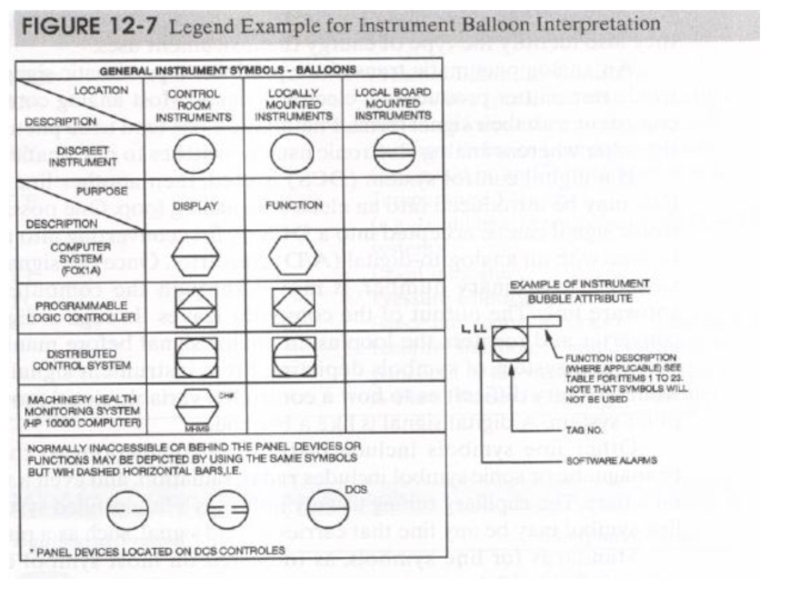
All PFDs and P&IDs should have an associated legend. A legend
is an explanation of what the symbols and codes represent. The legend may be located in a small box or area located in the margin of the drawing or it may be so large that it occupies an entire page.
The PFD primarily illustrates the flow of material through the process. To do this, a PFD must include process equipment and piping symbols. PFDs may also include process flow notations and even some instrumentation. Generally, any piece of equipment that moves fluids or comes in direct contact with the flowing process is on the PFD.
The P&ID by comparison has the most of the items as a PFD with the addition of the control instrumentation and considerable mechanical details. A P&ID shows the entire control loop in proximity to the field instrumentation. Again, this is the a schematic representation of the loop, not drawing. A P&ID does not represent the actual physical placement of the components as they are situated within a plant or unit.

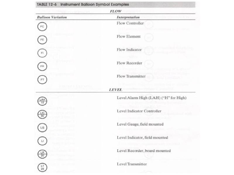
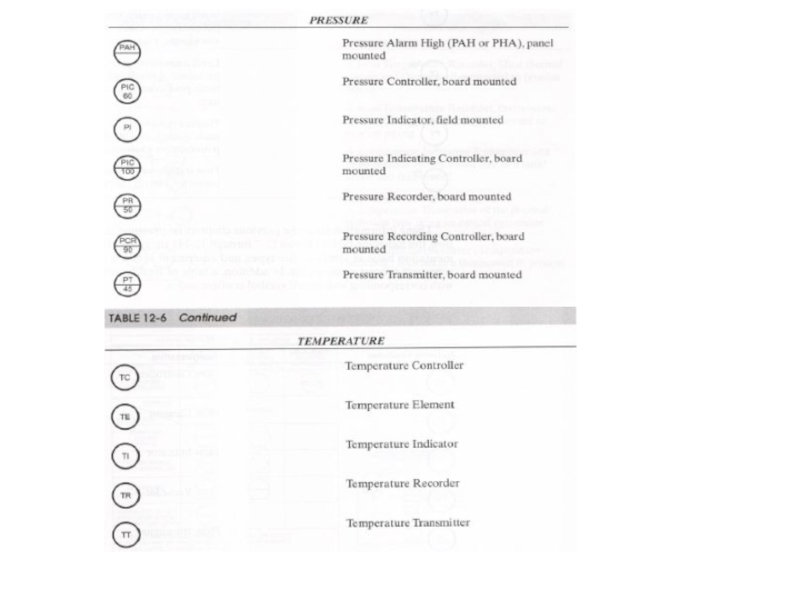
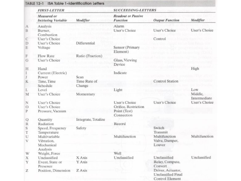
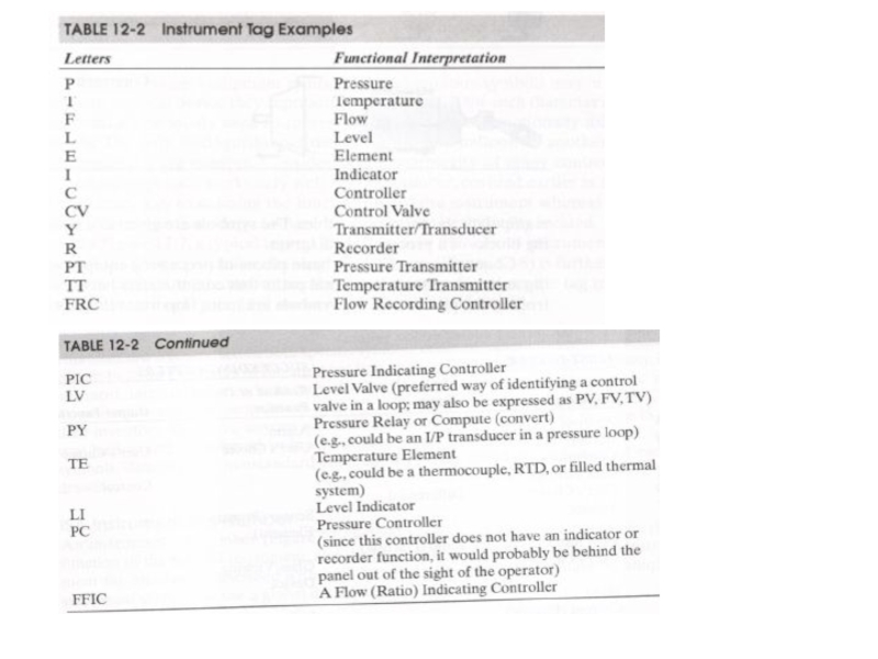
Слайд 7ISA Instrument Tag Number
An instrument tag number should identify the measured
variable, the function of the specific instrument, and the loop number. Accordingly, ISA instrument tag number is described with both letters and numbers and should be unique since most plants now use a global database to identify devices.
The first letter identifies the measured or initiating variable and the following letter describe the function of the instrument. Loop numbers are unique numbers assigned locally by the plant –engineering group. If loop has more than one instrument in the loop with the same functional identification, then suffix is added.
The first letter identifies the measured or initiating variable and the following letter describe the function of the instrument. Loop numbers are unique numbers assigned locally by the plant –engineering group. If loop has more than one instrument in the loop with the same functional identification, then suffix is added.


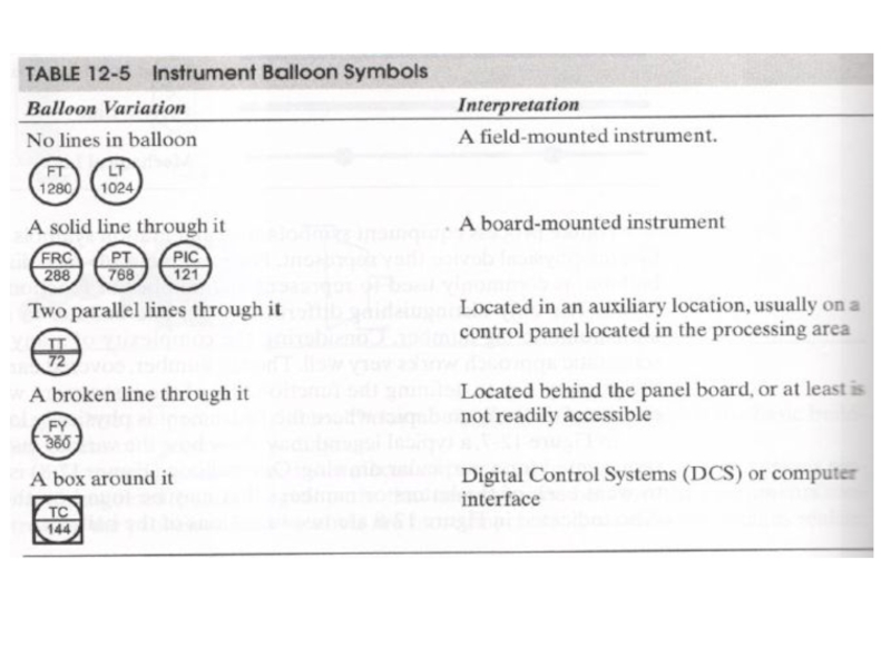
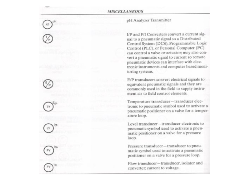
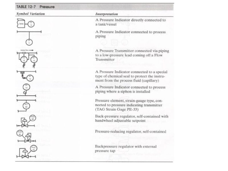
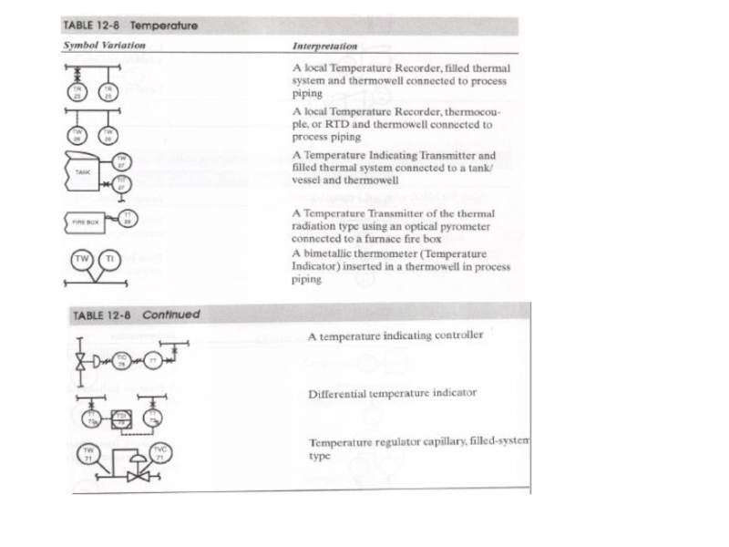
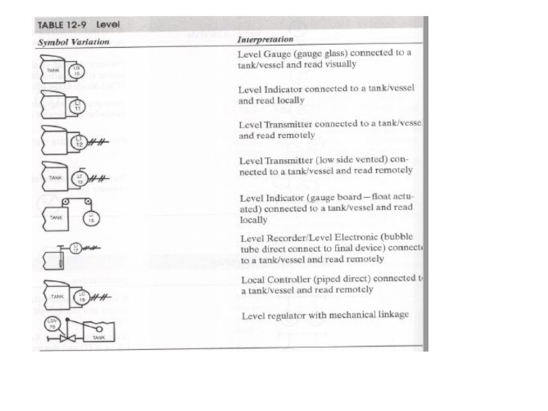
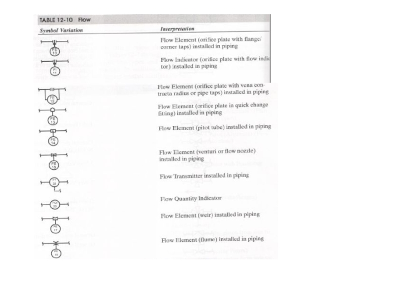
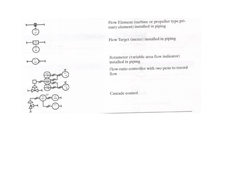
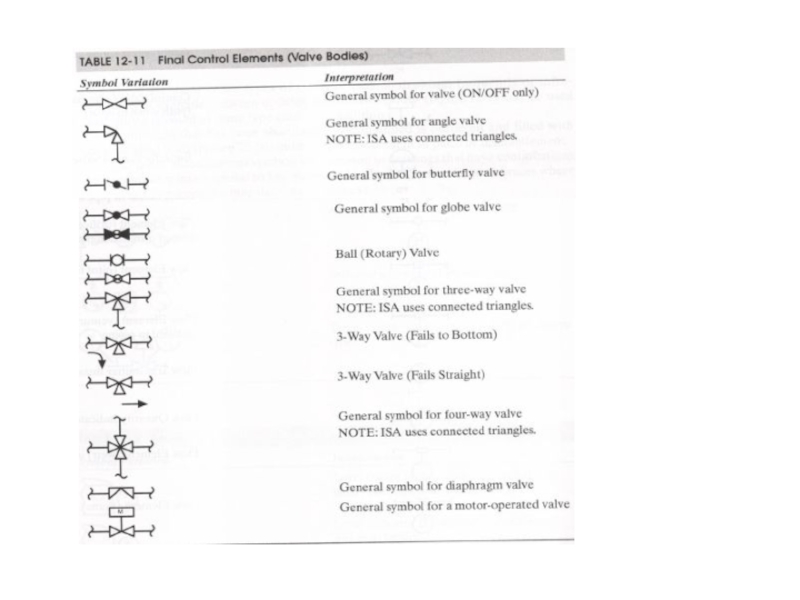
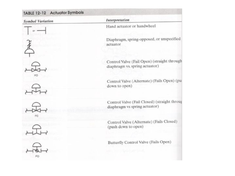
Слайд 12SYMBOLS
In a P&ID, a circle represents individual measurement instruments,
such as transmitters,
sensors, and detectors
A square with a circle inside represents instruments that both display measurement readings and perform some control function

Слайд 13A hexagon represents computer functions, such as those carried out
by a
controller
A square with a diamond inside represents PLCs