- Главная
- Разное
- Дизайн
- Бизнес и предпринимательство
- Аналитика
- Образование
- Развлечения
- Красота и здоровье
- Финансы
- Государство
- Путешествия
- Спорт
- Недвижимость
- Армия
- Графика
- Культурология
- Еда и кулинария
- Лингвистика
- Английский язык
- Астрономия
- Алгебра
- Биология
- География
- Детские презентации
- Информатика
- История
- Литература
- Маркетинг
- Математика
- Медицина
- Менеджмент
- Музыка
- МХК
- Немецкий язык
- ОБЖ
- Обществознание
- Окружающий мир
- Педагогика
- Русский язык
- Технология
- Физика
- Философия
- Химия
- Шаблоны, картинки для презентаций
- Экология
- Экономика
- Юриспруденция
Introduction to Closed Cycle Cooling Systems (for MICE) презентация
Содержание
- 1. Introduction to Closed Cycle Cooling Systems (for MICE)
- 2. Introduction There are alternatives to standard “wet”
- 3. Cryocoolers Cryocoolers are closed cycle cooling
- 4. How do they work ? Displacer/Regenerator
- 5. How do they work? Cool
- 6. How do they work? Regenerator /displacer –
- 7. Regenerator Modern crycoolers can reach low temperatures
- 8. Cryocoolers Cryocoolers can be purchased to operate
- 9. Cryocoolers Cryocoolers can be purchased to operate
- 10. Cryocoolers - examples Cryocoolers are commonly used
- 11. Examples Cryogenics section is building the low
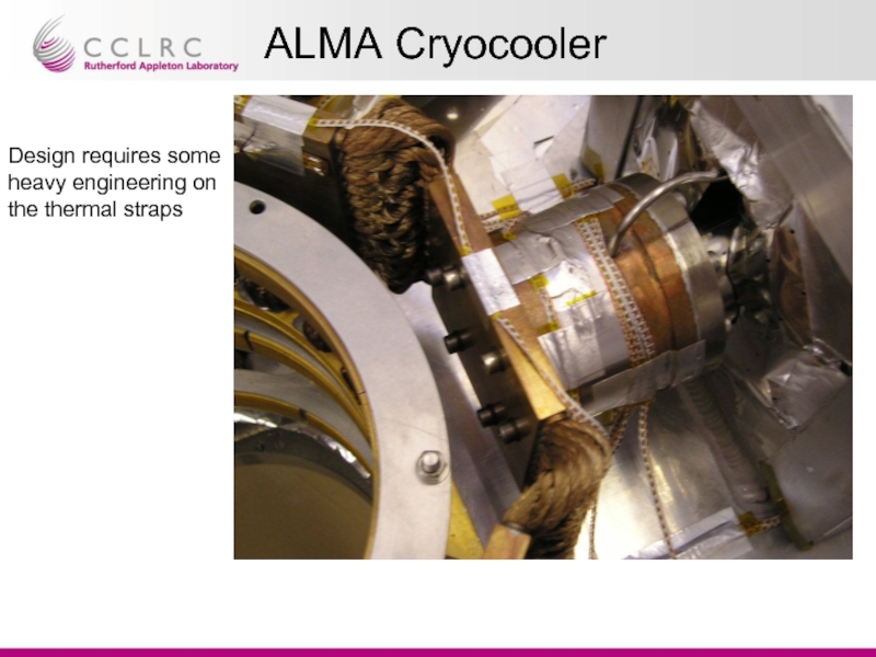
- 12. ALMA Cryocooler Design requires some heavy engineering on the thermal straps
- 13. What do we require ? Need refrigeration
- 14. Magnets These are estimates on the likely
- 15. Relative cost exercise Cryocooler cost 25 k£ Coil Heat
- 16. Absorber The absorber is a special case
- 17. Magnets and Detectors Magnets Magnets aren’t a
- 18. Key Points a) Staging of MICE will
- 19. Summary Proposal: RAL provide only refrigeration for
- 20. Applied Science Division END
Слайд 1Introduction to Closed Cycle Cooling Systems (for MICE)
Tom Bradshaw
Rutherford Appleton Laboratory
MICE
Слайд 2Introduction
There are alternatives to standard “wet” cryogenics that use closed cycle
I was asked to give a short talk on what are cryocoolers, how do they work and their benefits.
There are many types of closed cycle coolers – for MICE we can concentrate on two:
Gifford McMahon or GM cryocooler
Pulse tube refrigerator
Слайд 3Cryocoolers
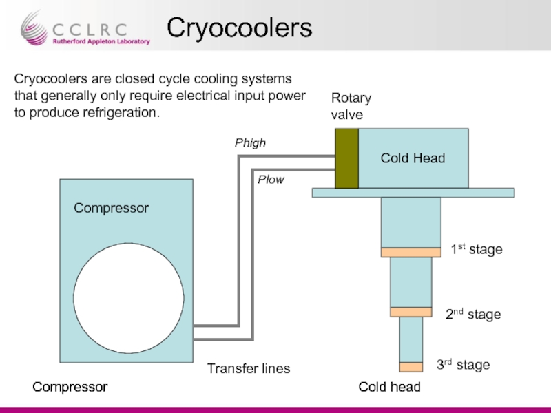
Cryocoolers are closed cycle cooling systems that generally only require
Cold Head
Compressor
Compressor
Compressor
Transfer lines
Cold head
Cold head
1st stage
2nd stage
3rd stage
Rotary valve
Phigh
Plow
Слайд 4How do they work ?
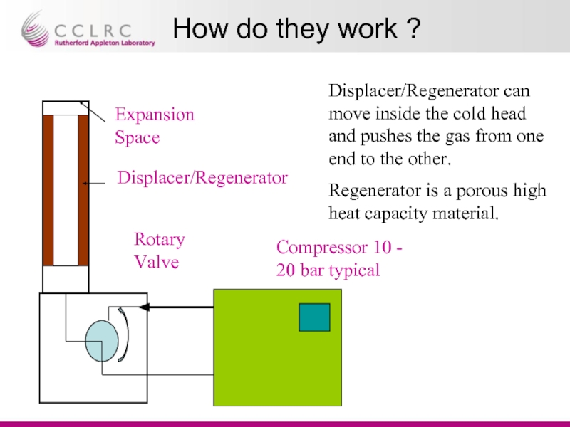
Displacer/Regenerator can move inside the cold head
Regenerator is a porous high heat capacity material.
Compressor 10 - 20 bar typical
Rotary Valve
Displacer/Regenerator
Expansion Space
Слайд 5How do they work?
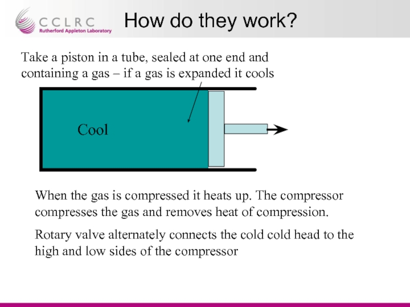
Cool
Take a piston in a tube, sealed at
When the gas is compressed it heats up. The compressor compresses the gas and removes heat of compression.
Rotary valve alternately connects the cold cold head to the high and low sides of the compressor
Слайд 6How do they work?
Regenerator /displacer – this shuttles the gas from
Compressor - The helium is circulated through the compressor where it is compressed and the heat of compression is removed.
The regenerator acts as a “cold store”. After the gas is expanded it passes through the regenerator – exchanges the “cold” with the regenerator material and passes back to the warm end. On the other half of the cycle as the gas goes towards the cold end it is pre-cooled by the regenerator.
The rotary valve switches the cold head from high pressure feed to low pressure
Слайд 7Regenerator
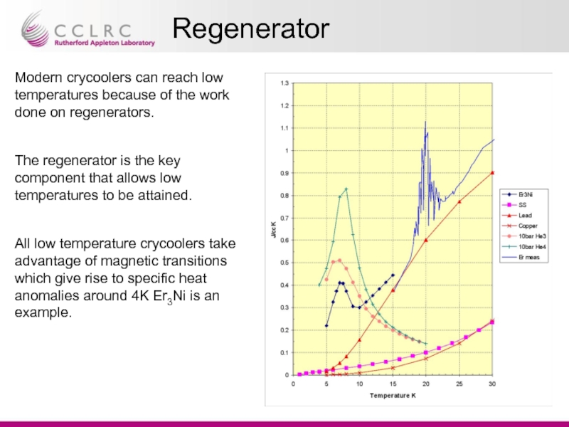
Modern crycoolers can reach low temperatures because of the work done
The regenerator is the key component that allows low temperatures to be attained.
All low temperature crycoolers take advantage of magnetic transitions which give rise to specific heat anomalies around 4K Er3Ni is an example.
Слайд 8Cryocoolers
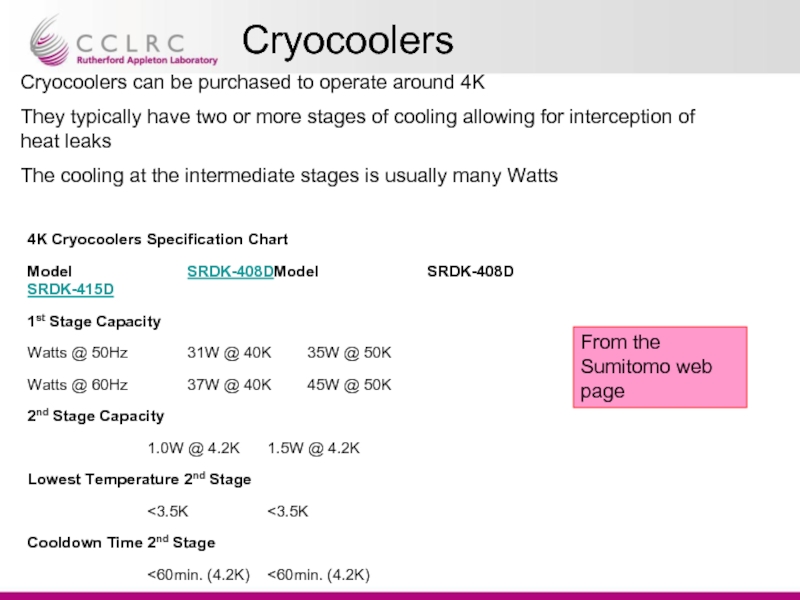
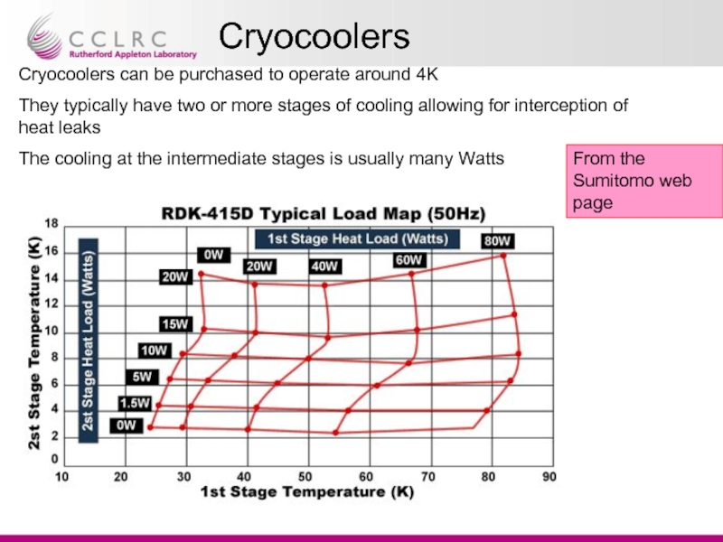
Cryocoolers can be purchased to operate around 4K
They typically have two
The cooling at the intermediate stages is usually many Watts
From the Sumitomo web page
4K Cryocoolers Specification Chart
Model SRDK-408DModel SRDK-408D SRDK-415D
1st Stage Capacity
Watts @ 50Hz 31W @ 40K 35W @ 50K
Watts @ 60Hz 37W @ 40K 45W @ 50K
2nd Stage Capacity
1.0W @ 4.2K 1.5W @ 4.2K
Lowest Temperature 2nd Stage
<3.5K <3.5K
Cooldown Time 2nd Stage
<60min. (4.2K) <60min. (4.2K)
Слайд 9Cryocoolers
Cryocoolers can be purchased to operate around 4K
They typically have two
The cooling at the intermediate stages is usually many Watts
From the Sumitomo web page
Слайд 10Cryocoolers - examples
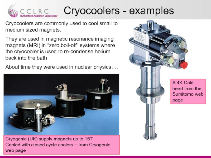
Cryocoolers are commonly used to cool small to medium
They are used in magnetic resonance imaging magnets (MRI) in “zero boil-off” systems where the cryocooler is used to re-condense helium back into the bath
About time they were used in nuclear physics….
A 4K Cold head from the Sumitomo web page
Cryogenic (UK) supply magnets up to 15T
Cooled with closed cycle coolers – from Cryogenic web page
Слайд 11Examples
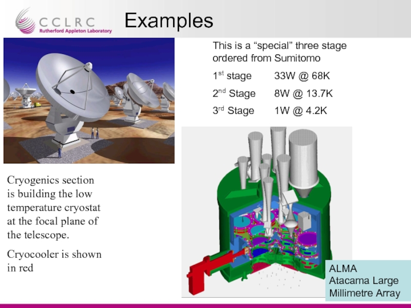
Cryogenics section is building the low temperature cryostat at the focal
Cryocooler is shown in red
This is a “special” three stage ordered from Sumitomo
1st stage 33W @ 68K
2nd Stage 8W @ 13.7K
3rd Stage 1W @ 4.2K
ALMA
Atacama Large Millimetre Array
Слайд 13What do we require ?
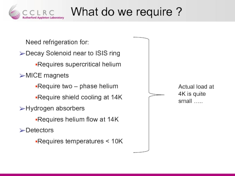
Need refrigeration for:
Decay Solenoid near to ISIS
Requires supercritical helium
MICE magnets
Require two – phase helium
Require shield cooling at 14K
Hydrogen absorbers
Requires helium flow at 14K
Detectors
Requires temperatures < 10K
Actual load at 4K is quite small …..
Слайд 14Magnets
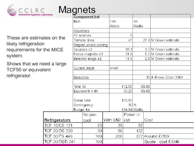
These are estimates on the likely refrigeration requirements for the MICE
Shows that we need a large TCF50 or equivalent refrigerator.
Слайд 15Relative cost exercise
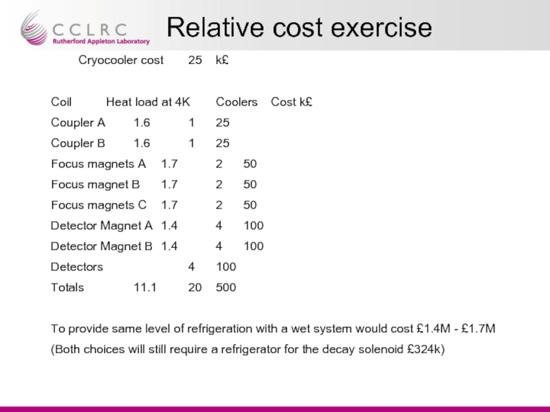
Cryocooler cost 25 k£
Coil Heat load at 4K Coolers Cost k£
Coupler A 1.6 1 25
Coupler B 1.6 1 25
Focus magnets
Focus magnet B 1.7 2 50
Focus magnets C 1.7 2 50
Detector Magnet A 1.4 4 100
Detector Magnet B 1.4 4 100
Detectors 4 100
Totals 11.1 20 500
To provide same level of refrigeration with a wet system would cost £1.4M - £1.7M
(Both choices will still require a refrigerator for the decay solenoid £324k)
Слайд 16Absorber
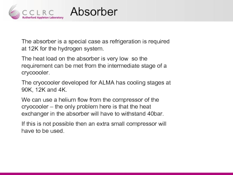
The absorber is a special case as refrigeration is required at
The heat load on the absorber is very low so the requirement can be met from the intermediate stage of a crycoooler.
The cryocooler developed for ALMA has cooling stages at 90K, 12K and 4K.
We can use a helium flow from the compressor of the cryocooler – the only problem here is that the heat exchanger in the absorber will have to withstand 40bar.
If this is not possible then an extra small compressor will have to be used.
Слайд 17Magnets and Detectors
Magnets
Magnets aren’t a particular problem as this is a
Design considerations:
Use of High Tc superconducting leads
Heat intercepts off the intermediate stages
Detectors
These are a prime candidate for the use of cryocoolers and IC are already looking at designs incorporating this technology
Issues
Cool-down time for many of the magnets will be long and we may have to incorporate nitrogen pre-cooling loops.
Testing is easier at the host institution and more thorough characterisation will be possible
The implementation will bring considerable cost savings – in most configurations most of the power is used to cool transfer lines
Слайд 18Key Points
a) Staging of MICE will mean that we will have
b) Cost - At the present the funding profile for MICE in the UK is not certain. There will be a large cost associated with the purchase of the cryogenic system.
c) Testing - If cryocoolers are used then each of the MICE "modules" can be tested independently and verified before shipping to RAL and integration. For example the detector group are keen on the idea.
d) Design - The cryocoolers can provide intermediate stages of cooling at low temperatures e.g. a three stage cooler could provide 3.8K, 14K and 90K. Can use high Tc current leads to minimise heat loads.
e) May be a pre-cooling issue – we will need to cool down the magnets in a day or two.
Слайд 19Summary
Proposal:
RAL provide only refrigeration for the decay solenoid
Providers of MICE modules
RAL will provide facilities for pre-cooling magnets to 80K via Nitrogen cooling
