- Главная
- Разное
- Дизайн
- Бизнес и предпринимательство
- Аналитика
- Образование
- Развлечения
- Красота и здоровье
- Финансы
- Государство
- Путешествия
- Спорт
- Недвижимость
- Армия
- Графика
- Культурология
- Еда и кулинария
- Лингвистика
- Английский язык
- Астрономия
- Алгебра
- Биология
- География
- Детские презентации
- Информатика
- История
- Литература
- Маркетинг
- Математика
- Медицина
- Менеджмент
- Музыка
- МХК
- Немецкий язык
- ОБЖ
- Обществознание
- Окружающий мир
- Педагогика
- Русский язык
- Технология
- Физика
- Философия
- Химия
- Шаблоны, картинки для презентаций
- Экология
- Экономика
- Юриспруденция
Draining Effect of a Tile Line презентация
Содержание
- 1. Draining Effect of a Tile Line
- 2. The class of problems involving flow of
- 3. Tile lines, horizontal galleries, trenches and,
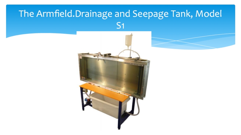
- 4. The Armfield.Drainage and Seepage Tank, Model S1
- 5. Tile drainage is an agriculture practice that removes
- 6. Equipment Diagrams 1)sand tank 2) water inlet
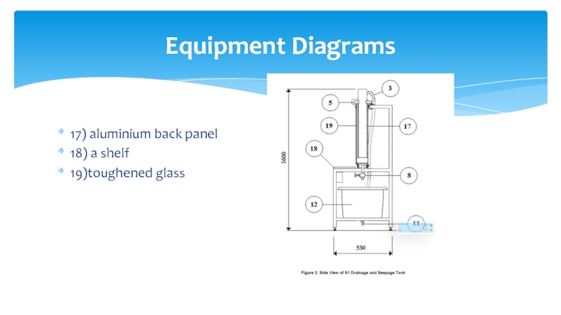
- 7. 17) aluminium back panel 18) a shelf 19)toughened glass Equipment Diagrams
- 8. Theory
- 9. Theory
- 10. Tile drains inserted in any of six
- 11. The space in the tank between the
- 12. Experimental stage
- 13. We have know how to calculate the
- 14. S1 Issue 16 Instruction Manual Flow of fluids throw porous materials R.Kolinz References
- 15. Thanks for attention
Слайд 1Draining Effect of a Tile Line
Made by : Ospanov Nursultan
Supervised
Practice Supervisor: Koldas Asetzhan
Слайд 2The class of problems involving flow of water through permeable media
In the laboratory, we have the advantage of being able to use homogenius materials of known properties. This simplifies the problem and makes it possible toreduce the number of components involved.
Following experiment has been designed to demonstrate the most typical situations that arise in dealing with water as it moves through a permeable medium. The situations described are mostly "engineering" situations. In addition to the water and the medium through which it moves, they usually involve some artificial, or"engineering" element like a wall, a dam, a tile line etc.
Introduction
Слайд 3 Tile lines, horizontal galleries, trenches and, sometimes, vertical wells are
The objective of this experiment is to show, by visualising the flow lines, how a tile line works (ie. how it forces the end-sections of flow lines to concentrate on one point).
Objective
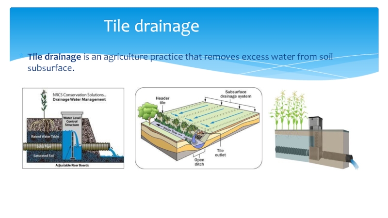
Слайд 5Tile drainage is an agriculture practice that removes excess water from soil
Tile drainage
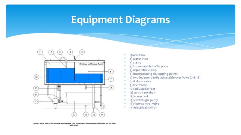
Слайд 6Equipment Diagrams
1)sand tank
2) water inlet
3) clamp
4) impermeable baffle plate
5) adjustable
6) incorporating six tapping points
7) two independently adjustable overflows (7 & 16)
8) A drain valve
9) the frame
10) adjustable feet
11) sump tank drain
12) sump tank
13) centrifugal pump
14) flow control valve
15) electrical switch
Слайд 10Tile drains inserted in any of six locations in the aluminium
The drains are fitted into the tank at two of the six positions. Space around the overflows is kept free by using vertical sheets of perforated metal, which can be supported by the overflow pipes
Experimental stage
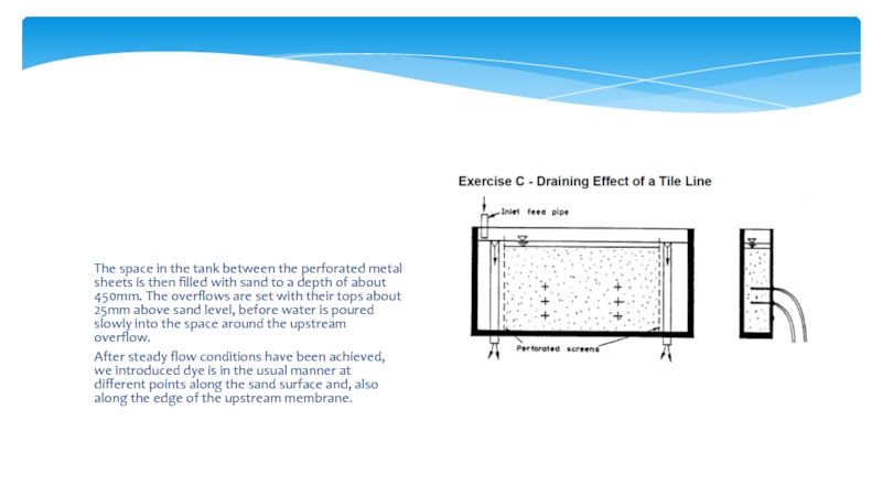
Слайд 11The space in the tank between the perforated metal sheets is
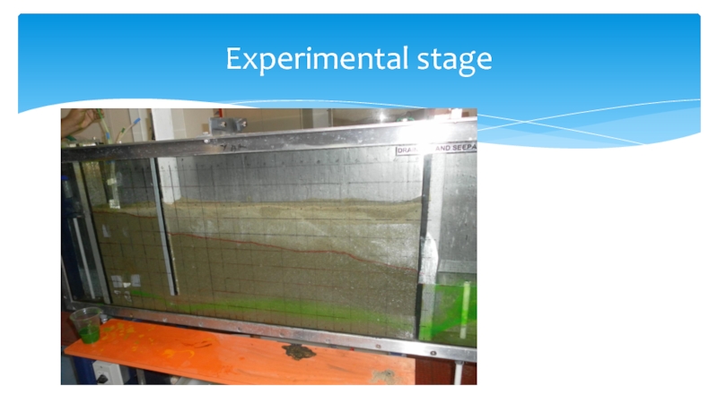
After steady flow conditions have been achieved, we introduced dye is in the usual manner at different points along the sand surface and, also along the edge of the upstream membrane.
Слайд 13We have know how to calculate the K(very interesting physical property
By visualising the flow lines we have seen how tile line works
Conclusion
(What I have learned from this project)
