- Главная
- Разное
- Дизайн
- Бизнес и предпринимательство
- Аналитика
- Образование
- Развлечения
- Красота и здоровье
- Финансы
- Государство
- Путешествия
- Спорт
- Недвижимость
- Армия
- Графика
- Культурология
- Еда и кулинария
- Лингвистика
- Английский язык
- Астрономия
- Алгебра
- Биология
- География
- Детские презентации
- Информатика
- История
- Литература
- Маркетинг
- Математика
- Медицина
- Менеджмент
- Музыка
- МХК
- Немецкий язык
- ОБЖ
- Обществознание
- Окружающий мир
- Педагогика
- Русский язык
- Технология
- Физика
- Философия
- Химия
- Шаблоны, картинки для презентаций
- Экология
- Экономика
- Юриспруденция
AT - A4AF3. Automatic Transaxle презентация
Содержание
- 1. AT - A4AF3. Automatic Transaxle
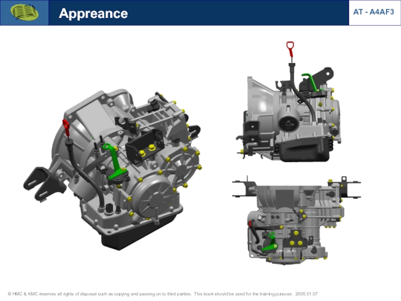
- 2. Appreance AT - A4AF3
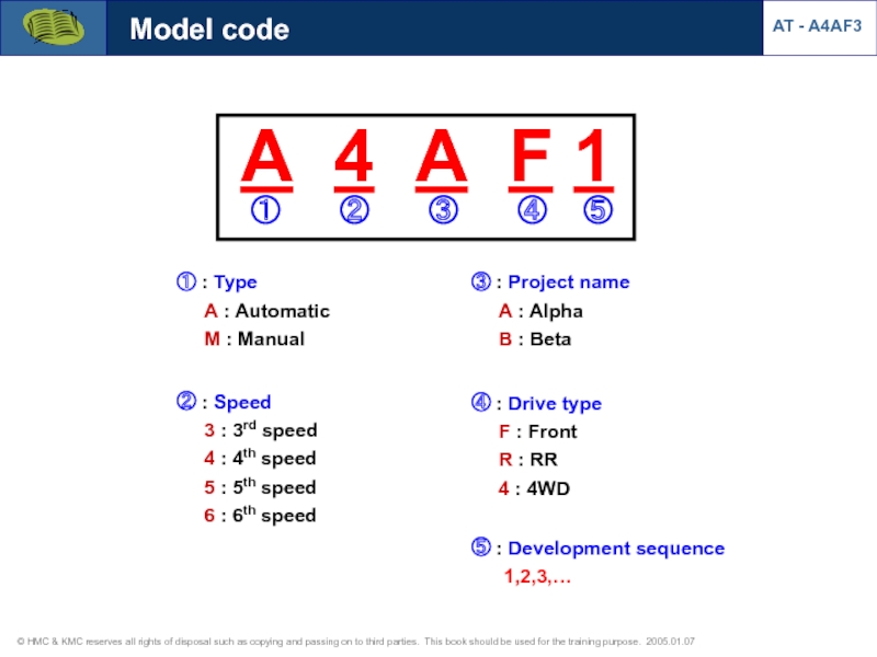
- 3. ③ : Project name
- 4. Location of PCM AT - A4AF3
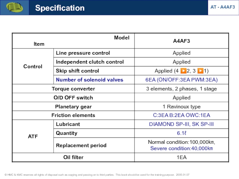
- 5. Specification AT - A4AF3
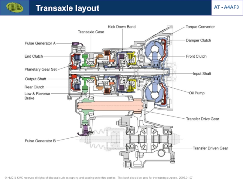
- 6. Transaxle layout AT - A4AF3
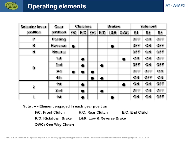
- 7. Note : ● - Element engaged in
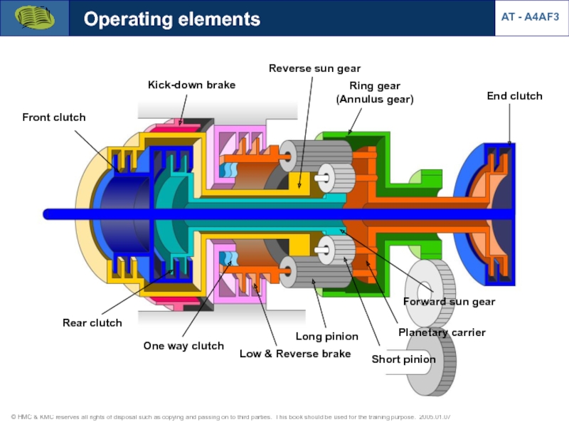
- 8. Short pinion Long pinion Ring gear (Annulus
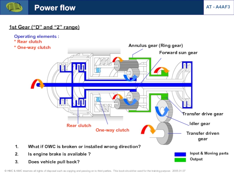
- 9. 1st Gear (“D” and “2” range) Operating
- 10. 1st Gear (“L” range) Operating elements :
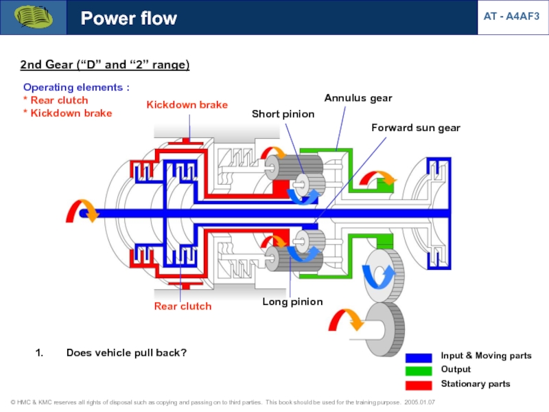
- 11. 2nd Gear (“D” and “2” range) Operating
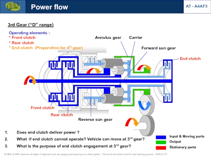
- 12. 3rd Gear (“D” range) Operating elements :
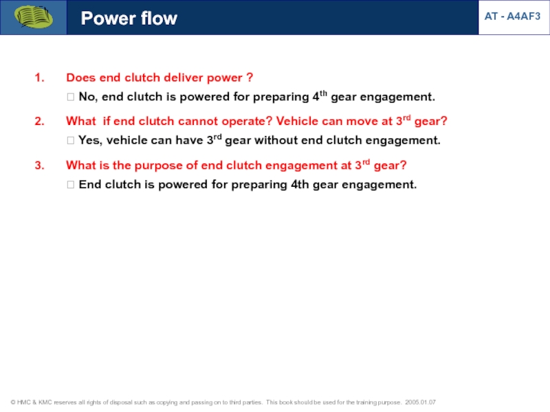
- 13. Does end clutch deliver power ? ?
- 14. 4th Gear (“D” range) Operating elements :
- 15. Reverse range Operating elements : * Front
- 16. AT - A4AF3 Power flow Reverse range
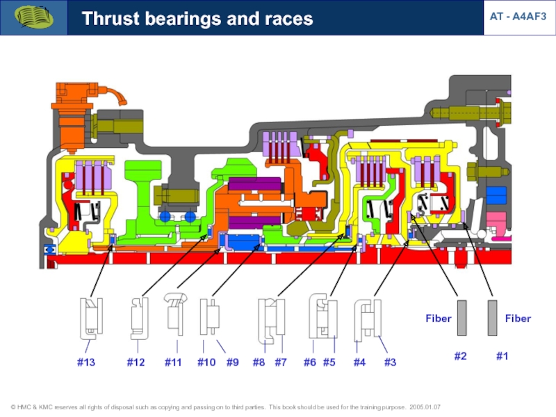
- 17. #1 #2 #13 #12 #11
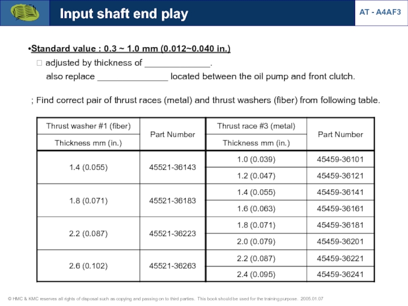
- 18. Input shaft end play Standard value :
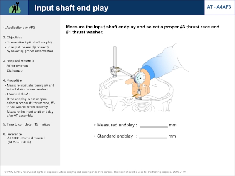
- 19. Measure the input shaft endplay and select
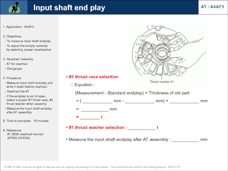
- 20. #3 thrust race selection
- 21. Front clutch Engaged at D3, R
- 22. Input shaft Rear clutch retainer Rear clutch
- 23. End clutch Engaged at D3,4 (powered
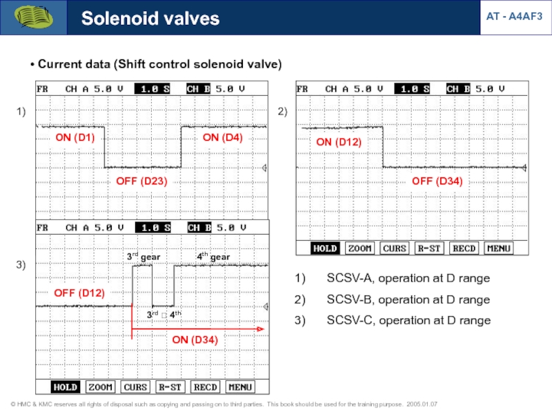
- 24. Kick-down drum Kick-down band Piston rod &
- 25. Kick down brake Kickndown brake servo piston
- 26. ? Service Point Symptom
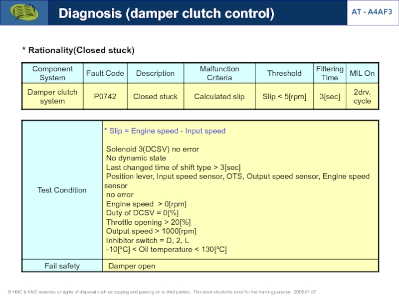
- 27. ① Loosen the adjust screw lock nut
- 28. ③ Tighten the adjust screw (Torque :
- 29. Kick down brake adjustment AT - A4AF3
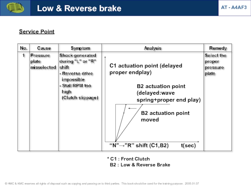
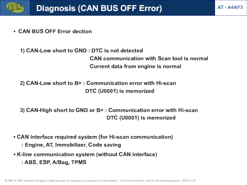
- 30. Low & Reverse brake Engaged
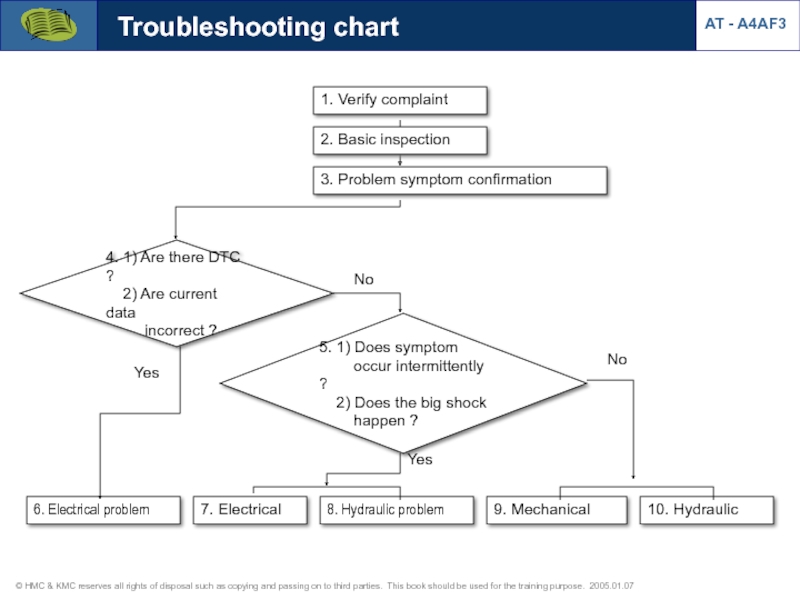
- 31. Service Point “N”→”R” shift (C1,B2)
- 32. Free Lock Outer race
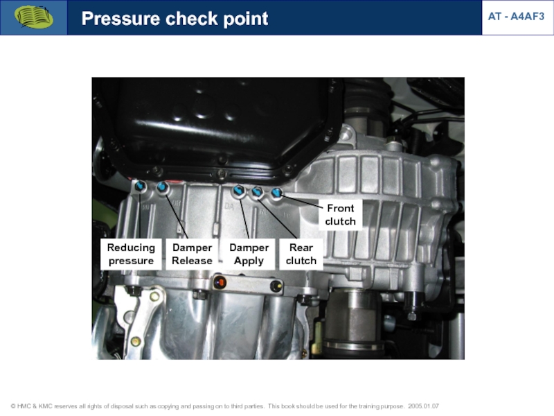
- 33. Pressure check point Reducing pressure Damper Release
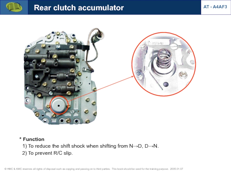
- 34. * Function 1) To reduce the
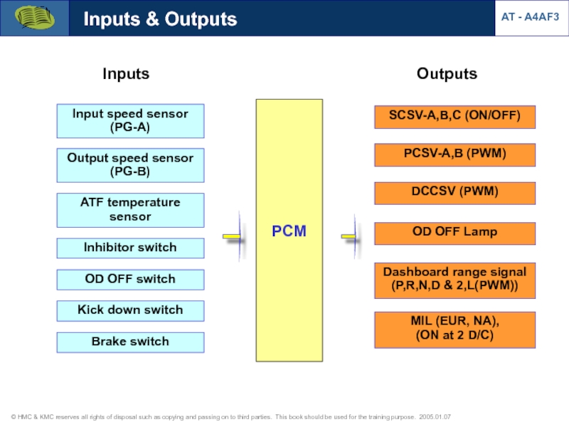
- 35. Outputs Inputs SCSV-A,B,C (ON/OFF) PCSV-A,B
- 36. Input speed sensor (PG-A) PG-A
- 37. Output speed sensor (PG-B) Output speed sensor
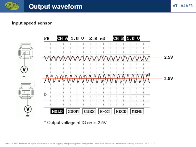
- 38. Output waveform 2.5V 2.5V Input speed sensor
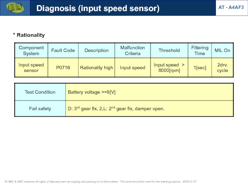
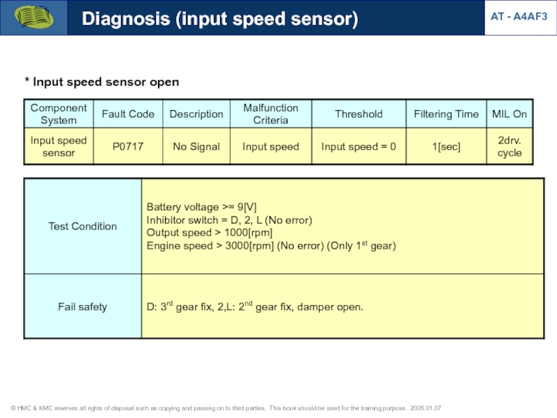
- 39. Diagnosis (input speed sensor) AT - A4AF3 * Rationality
- 40. * Input speed sensor open Diagnosis (input speed sensor) AT - A4AF3
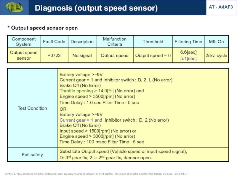
- 41. Diagnosis (output speed sensor) AT - A4AF3 * Output speed sensor open
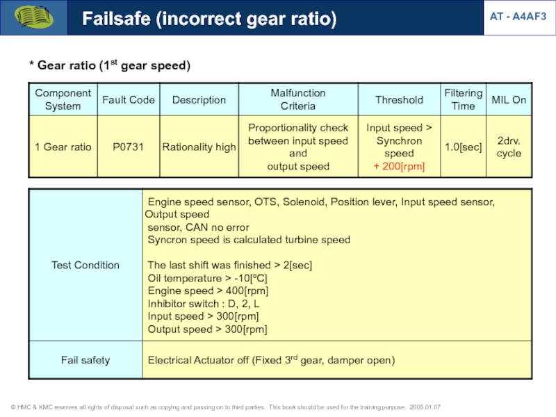
- 42. * Gear ratio (1st gear speed) Failsafe (incorrect gear ratio) AT - A4AF3
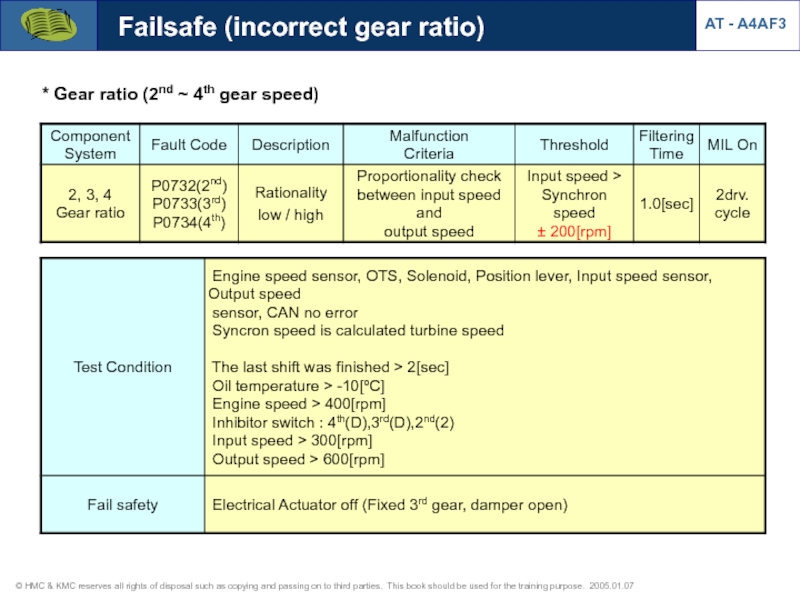
- 43. * Gear ratio (2nd ~ 4th gear speed) Failsafe (incorrect gear ratio) AT - A4AF3
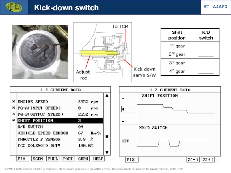
- 44. Kick-down switch AT - A4AF3
- 45. Diagnosis (K/D switch) * K/D switch open
- 46. Brake switch AT - A4AF3 [Brake switch
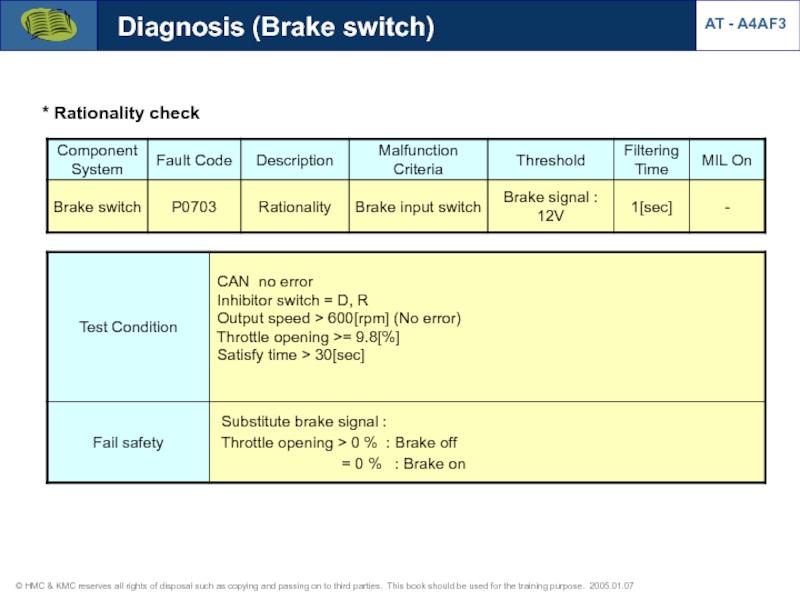
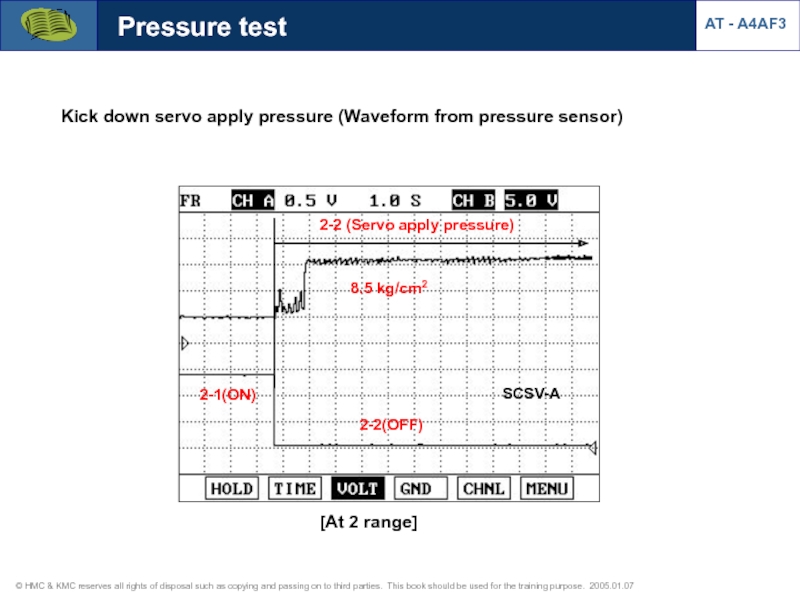
- 47. Diagnosis (Brake switch) AT - A4AF3 * Rationality check
- 48. Oil temperature sensor [Valve body] Oil
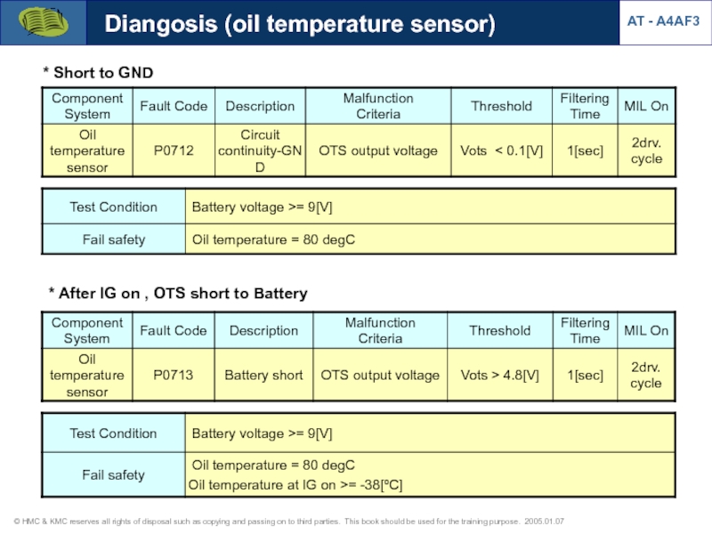
- 49. Diangosis (oil temperature sensor) * Oil temperature
- 50. Diangosis (oil temperature sensor) AT - A4AF3
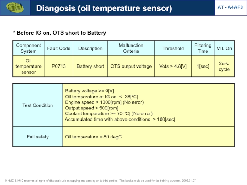
- 51. Diangosis (oil temperature sensor) AT - A4AF3 * Before IG on, OTS short to Battery
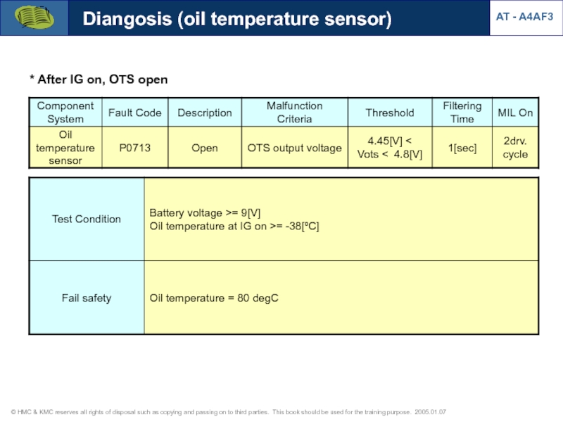
- 52. Diangosis (oil temperature sensor) AT - A4AF3 * After IG on, OTS open
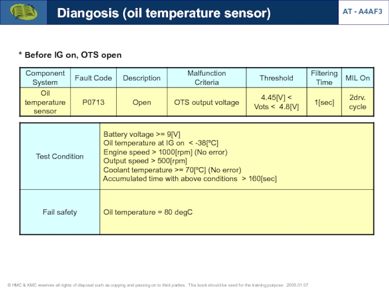
- 53. Diangosis (oil temperature sensor) AT - A4AF3 * Before IG on, OTS open
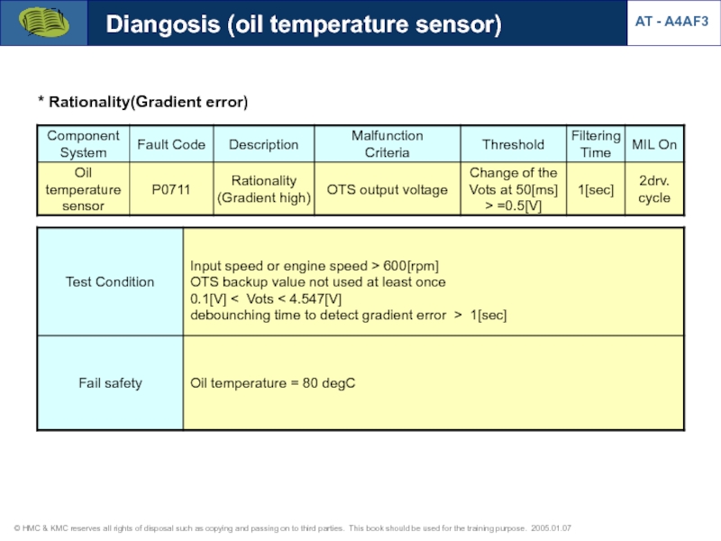
- 54. Diangosis (oil temperature sensor) AT - A4AF3 * Rationality(Gradient error)
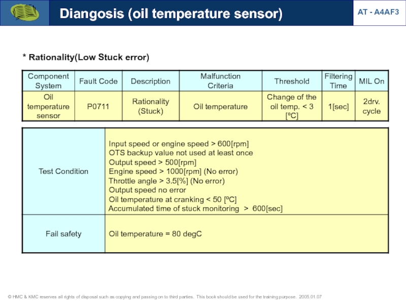
- 55. Diangosis (oil temperature sensor) AT - A4AF3 * Rationality(Low Stuck error)
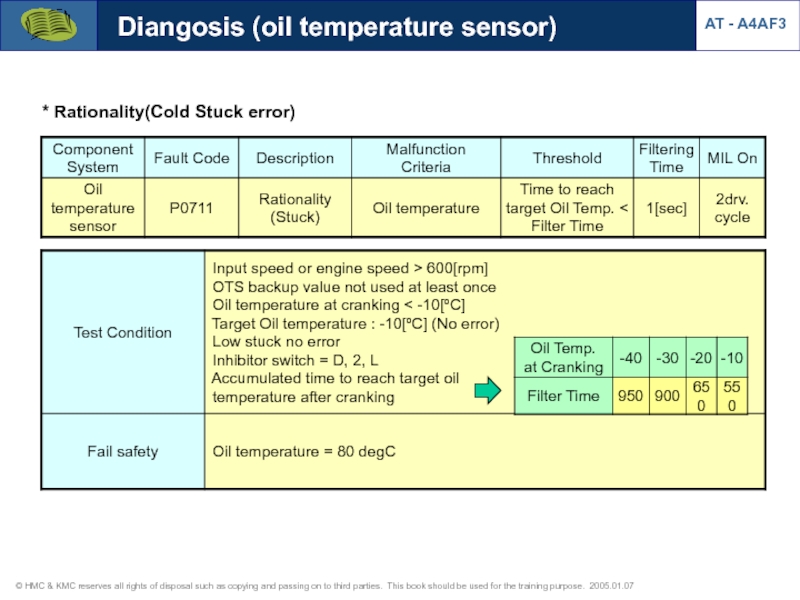
- 56. Diangosis (oil temperature sensor) AT - A4AF3 * Rationality(Cold Stuck error)
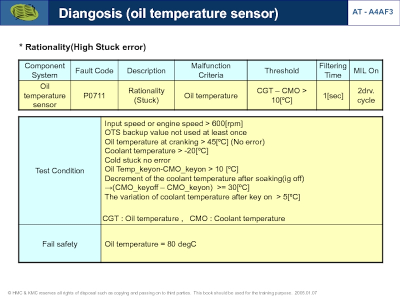
- 57. * Rationality(High Stuck error) Diangosis (oil temperature sensor) AT - A4AF3
- 58. Dashboard range signal AT - A4AF3 Cluster
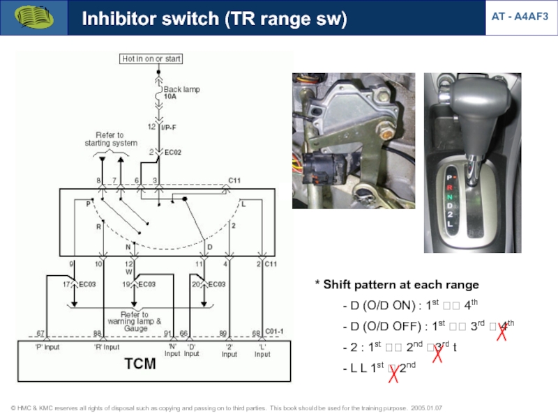
- 59. Inhibitor switch (TR range sw) * Shift
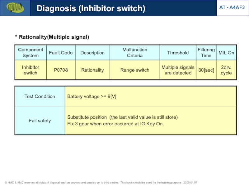
- 60. * Rationality(Multiple signal) Diagnosis (Inhibitor switch) AT - A4AF3
- 61. * Inhibitor switch open Diagnosis (Inhibitor switch) AT - A4AF3
- 62. AT - A4AF3 Diagnosis (Inhibitor switch) 1.
- 63. AT - A4AF3 Diagnosis (Inhibitor switch) 1.
- 64. AT - A4AF3 Diagnosis (Inhibitor switch) 1.
- 65. AT - A4AF3 Diagnosis (Inhibitor switch) 1.
- 66. AT - A4AF3 Diagnosis (Inhibitor switch) 1.
- 67. AT - A4AF3 Diagnosis (Inhibitor switch) 1.
- 68. 1. Type - On/Off control
- 69. Solenoid valves Operation table at D
- 70. Solenoid valves Current data (Damper clutch
- 71. Solenoid valves Current data (Pressure control
- 72. Solenoid valves Current data (Shift control
- 73. Solenoid valves Circuit diagram [DCCSV duty signal] [PCSV-A duty signal-duty 100%] AT - A4AF3
- 74. Diagnosis (solenoid valves) [Failsafe: 3rd gear hold at D,2,L] AT - A4AF3
- 75. Diagnosis (damper clutch control) AT - A4AF3 * Rationality(Closed stuck)
- 76. Diagnosis (damper clutch control) AT - A4AF3 * Rationality(Open stuck)
- 77. Diagnosis (CAN BUS OFF Error) AT - A4AF3 * CAN BUS OFF
- 78. Diagnosis (CAN BUS OFF Error) AT -
- 79. 1. Verify complaint 3. Problem symptom confirmation
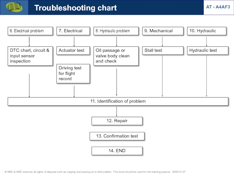
- 80. 6. Electrical problem 7. Electrical 8.
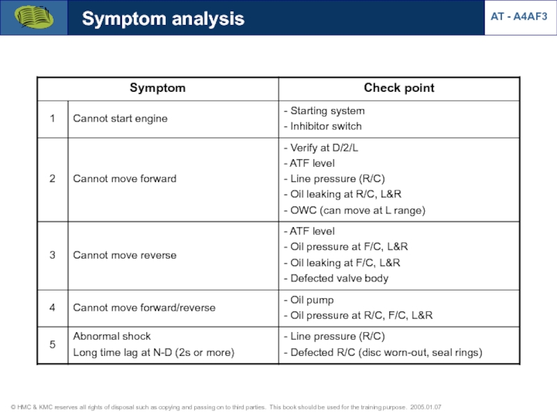
- 81. Symptom analysis AT - A4AF3
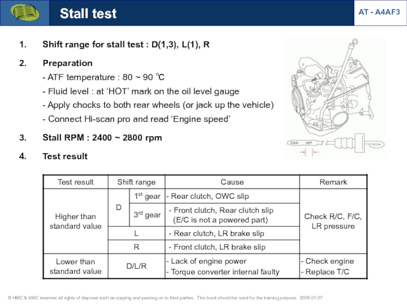
- 82. AT - A4AF3 Stall test Shift range
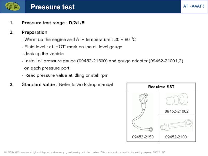
- 83. Pressure test Pressure test range : D/2/L/R
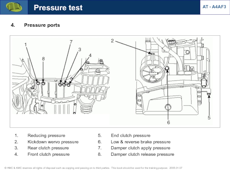
- 84. Pressure test Pressure ports AT - A4AF3
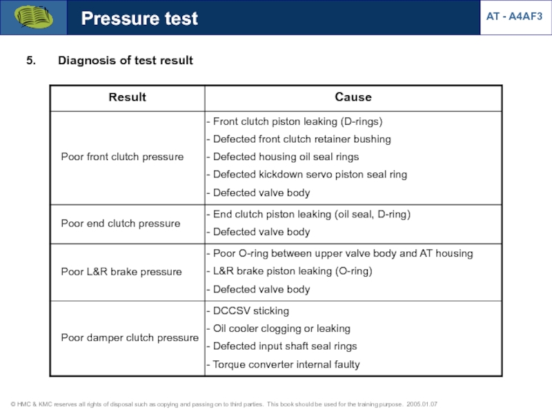
- 85. Pressure test Diagnosis of test result AT - A4AF3
- 86. AT Tester with adapter cables for AT
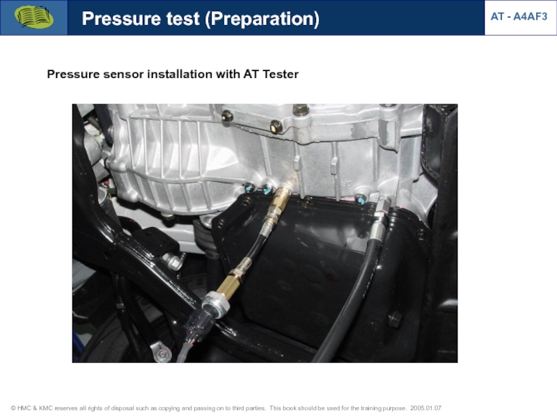
- 87. Pressure sensor installation with AT Tester AT
- 88. Pressure test (Preparation) Pressure sensor installation with AT Tester AT - A4AF3
- 89. [R/C pressure & PCSV-B operation at N?D?N]
- 90. AT - A4AF3 Pressure test 1) Rear
- 91. Pressure test Damper clutch pressure (Waveform from
- 92. Damper clutch pressure Pressure test [At D
- 93. Pressure test [At 2 range] [At L
- 94. Pressure test Kick down servo apply pressure
- 95. Kick down servo apply pressure (Waveform from
- 96. L&R brake pressure (Waveform from pressure sensor)
- 97. L&R brake stall pressure Pressure test [R
Слайд 3③ : Project name
A : Alpha
① : Type
A : Automatic
M : Manual
② : Speed
3 : 3rd speed
4 : 4th speed
5 : 5th speed
6 : 6th speed
④ : Drive type
F : Front
R : RR
4 : 4WD
⑤ : Development sequence
1,2,3,…
Model code
AT - A4AF3
Слайд 7Note : ● - Element engaged in each gear position
Operating elements
AT - A4AF3
Слайд 8Short pinion
Long pinion
Ring gear
(Annulus gear)
Forward sun gear
Reverse sun gear
End clutch
Front clutch
Rear
One way clutch
Kick-down brake
Low & Reverse brake
Operating elements
AT - A4AF3
Planetary carrier
Слайд 91st Gear (“D” and “2” range)
Operating elements :
* Rear clutch
* One-way
Forward sun gear
Transfer drive gear
Idler gear
Transfer driven gear
Rear clutch
One-way clutch
Annulus gear (Ring gear)
Power flow
AT - A4AF3
What if OWC is broken or installed wrong direction?
Is engine brake is available ?
Does vehicle pull back?
Input & Moving parts
Output
Слайд 101st Gear (“L” range)
Operating elements :
* Rear clutch
* Low-reverse brake
Short pinion
Carrier
Forward
Rear clutch
Long pinion
Annulus gear
Low-reverse brake
Power flow
AT - A4AF3
Is engine brake is available ?
Does vehicle pull back?
Input & Moving parts
Output
Stationary parts
Слайд 112nd Gear (“D” and “2” range)
Operating elements :
* Rear clutch
* Kickdown
Short pinion
Forward sun gear
Kickdown brake
Annulus gear
Rear clutch
Long pinion
Power flow
AT - A4AF3
Does vehicle pull back?
Input & Moving parts
Output
Stationary parts
Слайд 123rd Gear (“D” range)
Operating elements :
* Front clutch
* Rear clutch
* End
Forward sun gear
Carrier
End clutch
Annulus gear
Reverse sun gear
Rear clutch
Front clutch
Power flow
AT - A4AF3
Does end clutch deliver power ?
What if end clutch cannot operate? Vehicle can move at 3rd gear?
What is the purpose of end clutch engagement at 3rd gear?
Input & Moving parts
Output
Stationary parts
Слайд 13Does end clutch deliver power ? ? No, end clutch is powered
What if end clutch cannot operate? Vehicle can move at 3rd gear? ? Yes, vehicle can have 3rd gear without end clutch engagement.
What is the purpose of end clutch engagement at 3rd gear? ? End clutch is powered for preparing 4th gear engagement.
Power flow
AT - A4AF3
Слайд 144th Gear (“D” range)
Operating elements :
* Kickdown brake
* End clutch
Kickdown brake
End
Long pinion
Carrier
Annulus gear
Reverse sun gear
Power flow
AT - A4AF3
Input & Moving parts
Output
Stationary parts
Слайд 15Reverse range
Operating elements :
* Front clutch
* Low-reverse brake
Low-reverse brake
Front clutch
Reverse sun
Carrier
Annulus gear
Long pinion
Power flow
AT - A4AF3
Input & Moving parts
Output
Stationary parts
Слайд 16AT - A4AF3
Power flow
Reverse range
Operating elements :
* Front clutch
* Low-reverse brake
Input
Locked
Output
Слайд 18Input shaft end play
Standard value : 0.3 ~ 1.0 mm (0.012~0.040
? adjusted by thickness of _____________. also replace ______________ located between the oil pump and front clutch.
; Find correct pair of thrust races (metal) and thrust washers (fiber) from following table.
AT - A4AF3
Слайд 19Measure the input shaft endplay and select a proper #3 thrust
Measured endplay : ___________ mm
Standard endplay : ___________ mm
1. Application : A4AF3
2. Objectives
- To measure input shaft endplay
- To adjust the endply correctly
by selecting proper race/washer
3. Required materials
- AT for overhaul
- Dial gauge
4. Procedure
- Measure input shaft endplay and
write it down before overhaul.
- Overhaul the AT
- If the endplay is out of spec.,
select a proper #1 thrust race, #3
thrust washer when assemly.
- Measure the input shaft endplay
after AT assembly.
5. Time to complete : 15 minutes
6. Reference
: AT 2005 overhaul manual
(ATMS-EG4DA)
Input shaft end play
AT - A4AF3
Слайд 20 #3 thrust race selection ? Equation :
#1 thrust washer selection : ___________ t
Input shaft end play
AT - A4AF3
Measure the input shaft endplay after AT assembly : ___________ mm
1. Application : A4AF3
2. Objectives
- To measure input shaft endplay
- To adjust the endply correctly
by selecting proper race/washer
3. Required materials
- AT for overhaul
- Dial gauge
4. Procedure
- Measure input shaft endplay and
write it down before overhaul.
- Overhaul the AT
- If the endplay is out of spec.,
select a proper #1 thrust race, #3
thrust washer when assemly.
- Measure the input shaft endplay
after AT assembly.
5. Time to complete : 15 minutes
6. Reference
: AT 2005 overhaul manual
(ATMS-EG4DA)
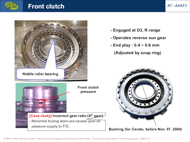
Слайд 21Front clutch
Engaged at D3, R range
Operates reverse sun gear
Bushing (for Cerato, before Nov. 07. 2004)
AT - A4AF3
Niddle roller bearing
[Case study] Incorrect gear ratio (4th gear)
: Abnormal busing worn-out causes poor oil
pressure supply to F/C.
Front clutch pressure
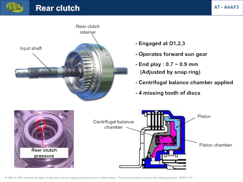
Слайд 22Input shaft
Rear clutch retainer
Rear clutch
Engaged at D1,2,3
Operates forward sun
End play : 0.7 ~ 0.9 mm (Adjusted by snap ring)
Centrifugal balance chamber applied
4 missing tooth of discs
Centrifugal balance chamber
Piston
Piston chamber
AT - A4AF3
Rear clutch pressure
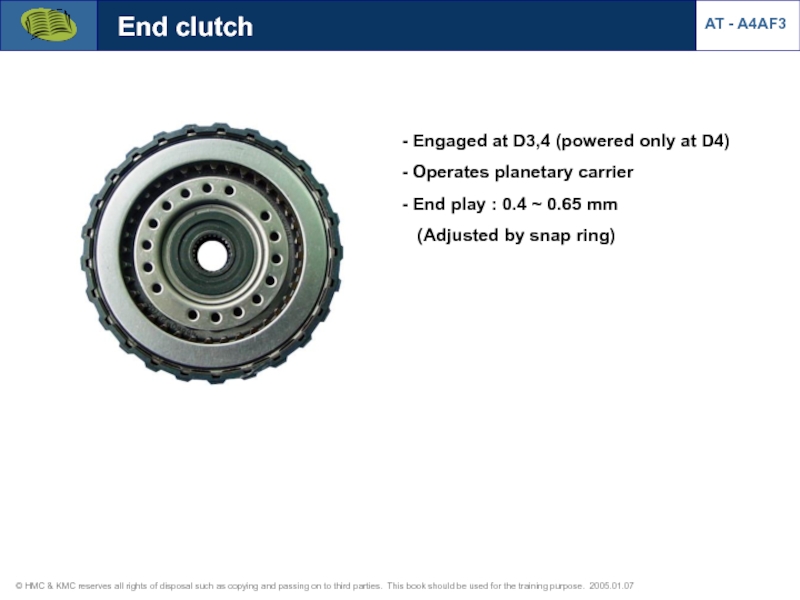
Слайд 23End clutch
Engaged at D3,4 (powered only at D4)
Operates planetary
End play : 0.4 ~ 0.65 mm (Adjusted by snap ring)
AT - A4AF3
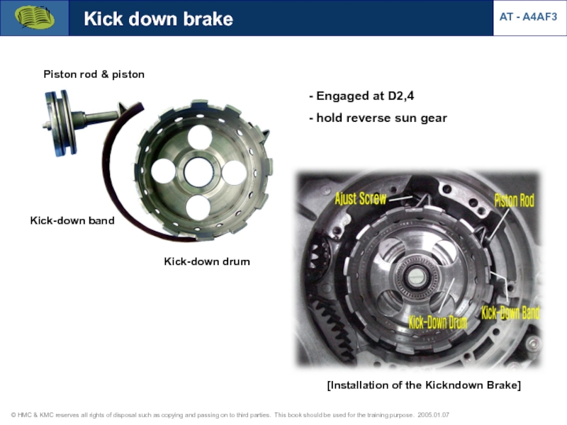
Слайд 24Kick-down drum
Kick-down band
Piston rod & piston
Kick down brake
Engaged at D2,4
hold reverse sun gear
[Installation of the Kickndown Brake]
AT - A4AF3
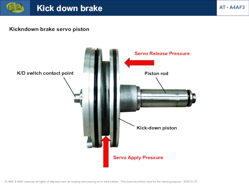
Слайд 25Kick down brake
Kickndown brake servo piston
Servo Release Pressure
Servo Apply Pressure
K/D switch
AT - A4AF3
Kick-down piston
Piston rod
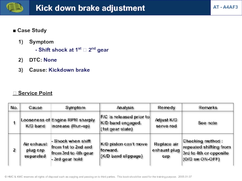
Слайд 26? Service Point
Symptom
- Shift shock at
DTC: None
Cause: Kickdown brake
■ Case Study
Kick down brake adjustment
AT - A4AF3
Слайд 27① Loosen the adjust screw lock nut
Kick down brake adjustment
② Tighten
AT - A4AF3
* Adjustment procedure
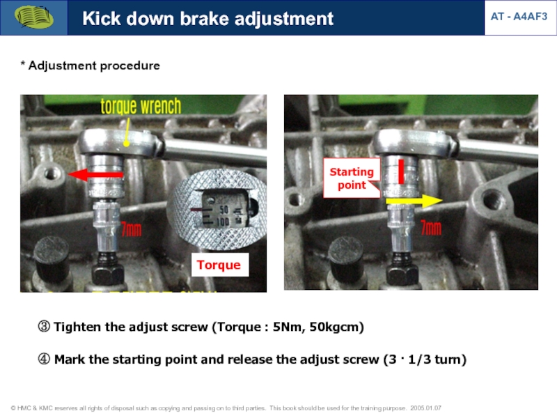
Слайд 28③ Tighten the adjust screw (Torque : 5Nm, 50kgcm)
Torque
④ Mark
Starting point
Kick down brake adjustment
AT - A4AF3
* Adjustment procedure
Слайд 29Kick down brake adjustment
AT - A4AF3
* Adjustment procedure
⑤ Tighten the lock
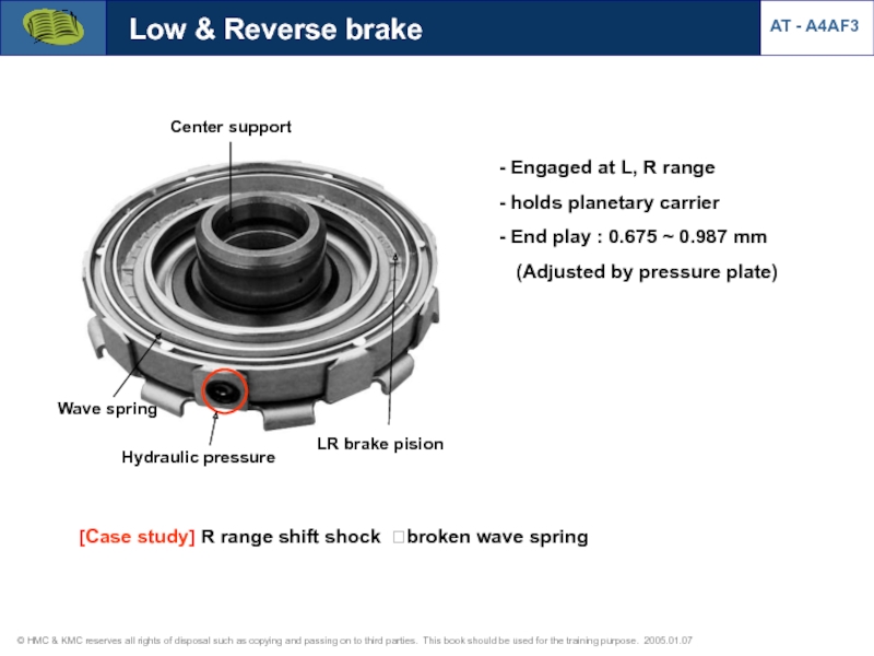
Слайд 30Low & Reverse brake
Engaged at L, R range
holds planetary
End play : 0.675 ~ 0.987 mm (Adjusted by pressure plate)
Hydraulic pressure
LR brake pision
Center support
Wave spring
[Case study] R range shift shock ?broken wave spring
AT - A4AF3
Слайд 31Service Point
“N”→”R” shift (C1,B2) t(sec)
B2 actuation point moved
C1
B2 actuation point (delayed:wave spring+proper end play)
* C1 : Front Clutch
B2 : Low & Reverse Brake
Low & Reverse brake
AT - A4AF3
Слайд 32
Free
Lock
Outer race
(planetary gear carrier)
Inner race
(Center support)
Sprag
Annulus gear
Short pinion
Long pinion
Forward
Carrier
One way clutch
Service Point
AT - A4AF3
Слайд 33Pressure check point
Reducing pressure
Damper Release
Damper Apply
Rear clutch
Front clutch
AT - A4AF3
Слайд 34* Function
1) To reduce the shift shock when shifting from
2) To prevent R/C slip.
Rear clutch accumulator
AT - A4AF3
Слайд 35
Outputs
Inputs
SCSV-A,B,C (ON/OFF)
PCSV-A,B (PWM)
DCCSV (PWM)
Input speed sensor (PG-A)
Output speed sensor
(PG-B)
ATF temperature sensor
Inhibitor
OD OFF switch
Kick down switch
Brake switch
PCM
Inputs & Outputs
AT - A4AF3
OD OFF Lamp
Dashboard range signal
(P,R,N,D & 2,L(PWM))
MIL (EUR, NA),
(ON at 2 D/C)
Слайд 36
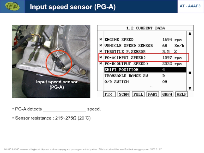
Input speed sensor (PG-A)
PG-A detects _________________ speed.
Sensor resistance :
Input speed sensor
(PG-A)
AT - A4AF3
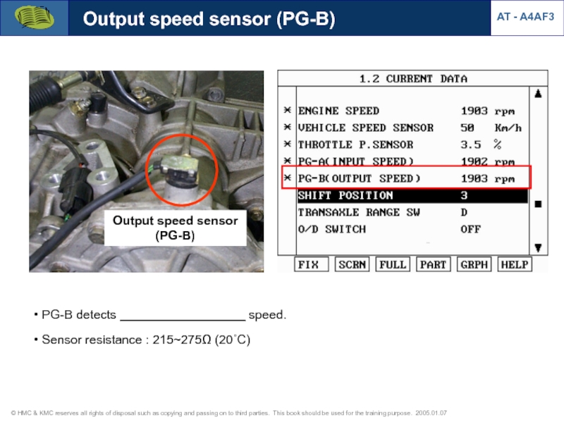
Слайд 37Output speed sensor (PG-B)
Output speed sensor
(PG-B)
PG-B detects __________________
Sensor resistance : 215~275Ω (20˚C)
AT - A4AF3
Слайд 46Brake switch
AT - A4AF3
[Brake switch signal]
Brake applied
High :12V
Low : 0V
Purpose
Damper
Output speed sensor failure detection (stall test detection)
Слайд 48Oil temperature sensor
[Valve body]
Oil temperature sensor
Pressure control
: PCSV
Damper clutch control : damper clutch On/Off control according to ATF temperature
High temperature control : performs different shift pattern when ATF temperature is too high (115 ℃)
AT - A4AF3
Слайд 49Diangosis (oil temperature sensor)
* Oil temperature sensor
AT - A4AF3
[Oil temperature-circuit open]
[DTC-circuit
[Oil temperature-failsafe]
Слайд 50Diangosis (oil temperature sensor)
AT - A4AF3
* Short to GND
* After IG
Слайд 58Dashboard range signal
AT - A4AF3
Cluster
Inhibitor switch
P
R
N
D
PCM
2
L
Dashboard range signal
(2, L, PWM)
[Trip computer
Duty at 2 range : 75 %
Duty at L range : 87 %
Слайд 59Inhibitor switch (TR range sw)
* Shift pattern at each range
- D
AT - A4AF3
Слайд 62AT - A4AF3
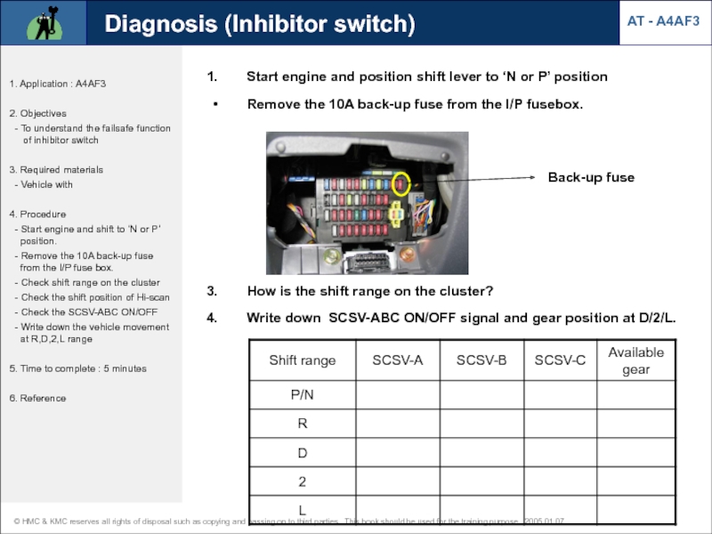
Diagnosis (Inhibitor switch)
1. Application : A4AF3
2. Objectives
- To
3. Required materials
- Vehicle with
4. Procedure
- Start engine and shift to ‘N or P’ position.
- Remove the 10A back-up fuse from the I/P fuse box.
- Check shift range on the cluster
- Check the shift position of Hi-scan
- Check the SCSV-ABC ON/OFF
- Write down the vehicle movement at R,D,2,L range
5. Time to complete : 5 minutes
6. Reference
Start engine and position shift lever to ‘N or P’ position
Remove the 10A back-up fuse from the I/P fusebox.
Back-up fuse
How is the shift range on the cluster?
Write down SCSV-ABC ON/OFF signal and gear position at D/2/L.
Слайд 63AT - A4AF3
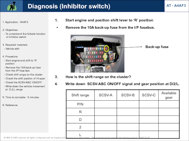
Diagnosis (Inhibitor switch)
1. Application : A4AF3
2. Objectives
- To
3. Required materials
- Vehicle with
4. Procedure
- Start engine and shift to ‘R’ position.
- Remove the 10A back-up fuse from the I/P fuse box.
- Check shift range on the cluster
- Check the shift position of Hi-scan
- Check the SCSV-ABC ON/OFF
- Write down the vehicle movement at D,2,L range
5. Time to complete : 5 minutes
6. Reference
Start engine and position shift lever to ‘R’ position
Remove the 10A back-up fuse from the I/P fusebox.
Back-up fuse
How is the shift range on the cluster?
Write down SCSV-ABC ON/OFF signal and gear position at D/2/L.
Слайд 64AT - A4AF3
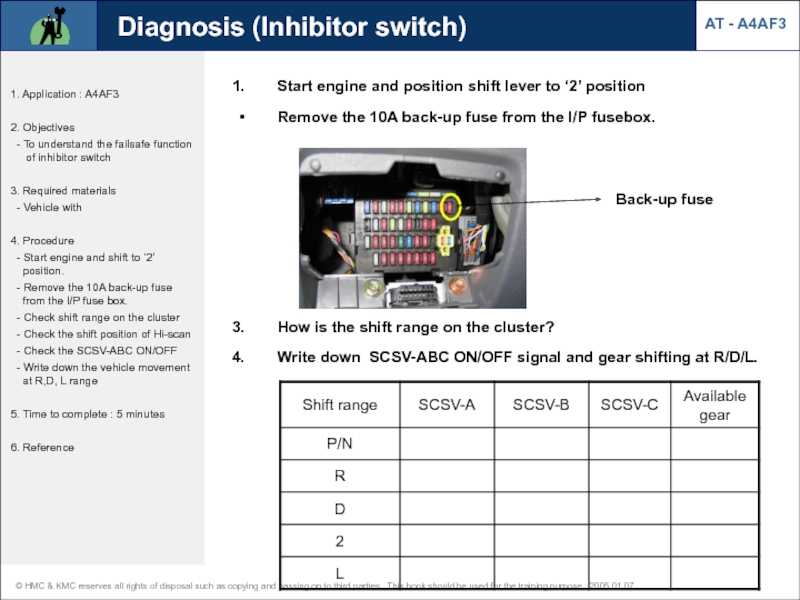
Diagnosis (Inhibitor switch)
1. Application : A4AF3
2. Objectives
- To
3. Required materials
- Vehicle with
4. Procedure
- Start engine and shift to 'D’ position.
- Remove the 10A back-up fuse from the I/P fuse box.
- Check shift range on the cluster
- Check the shift position of Hi-scan
- Check the SCSV-ABC ON/OFF
- Write down the vehicle movement at R,2,L range
5. Time to complete : 5 minutes
6. Reference
Start engine and position shift lever to ‘D’ position
Remove the 10A back-up fuse from the I/P fusebox.
Back-up fuse
How is the shift range on the cluster?
Write down SCSV-ABC ON/OFF signal and gear shifting at R/D/2/L.
Слайд 65AT - A4AF3
Diagnosis (Inhibitor switch)
1. Application : A4AF3
2. Objectives
- To
3. Required materials
- Vehicle with
4. Procedure
- Start engine and shift to ‘2’ position.
- Remove the 10A back-up fuse from the I/P fuse box.
- Check shift range on the cluster
- Check the shift position of Hi-scan
- Check the SCSV-ABC ON/OFF
- Write down the vehicle movement at R,D, L range
5. Time to complete : 5 minutes
6. Reference
Start engine and position shift lever to ‘2’ position
Remove the 10A back-up fuse from the I/P fusebox.
Back-up fuse
How is the shift range on the cluster?
Write down SCSV-ABC ON/OFF signal and gear shifting at R/D/L.
Слайд 66AT - A4AF3
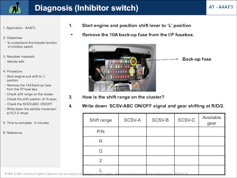
Diagnosis (Inhibitor switch)
1. Application : A4AF3
2. Objectives
- To
3. Required materials
- Vehicle with
4. Procedure
- Start engine and shift to ‘L’ position.
- Remove the 10A back-up fuse from the I/P fuse box.
- Check shift range on the cluster
- Check the shift position of Hi-scan
- Check the SCSV-ABC ON/OFF
- Write down the vehicle movement at R,D,2 range
5. Time to complete : 5 minutes
6. Reference
Start engine and position shift lever to ‘L’ position
Remove the 10A back-up fuse from the I/P fusebox.
Back-up fuse
How is the shift range on the cluster?
Write down SCSV-ABC ON/OFF signal and gear shifting at R/D/2.
Слайд 67AT - A4AF3
Diagnosis (Inhibitor switch)
1. Application : A4AF3
2. Objectives
- To
3. Required materials
- Vehicle with
4. Procedure
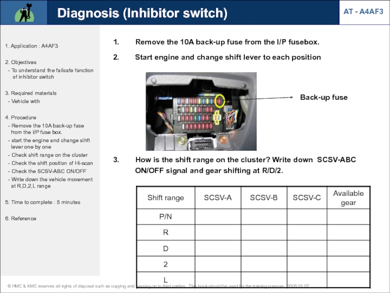
- Remove the 10A back-up fuse from the I/P fuse box.
- start the engine and change sihft lever one by one
- Check shift range on the cluster
- Check the shift position of Hi-scan
- Check the SCSV-ABC ON/OFF
- Write down the vehicle movement at R,D,2,L range
5. Time to complete : 5 minutes
6. Reference
Back-up fuse
How is the shift range on the cluster? Write down SCSV-ABC ON/OFF signal and gear shifting at R/D/2.
Remove the 10A back-up fuse from the I/P fusebox.
Start engine and change shift lever to each position
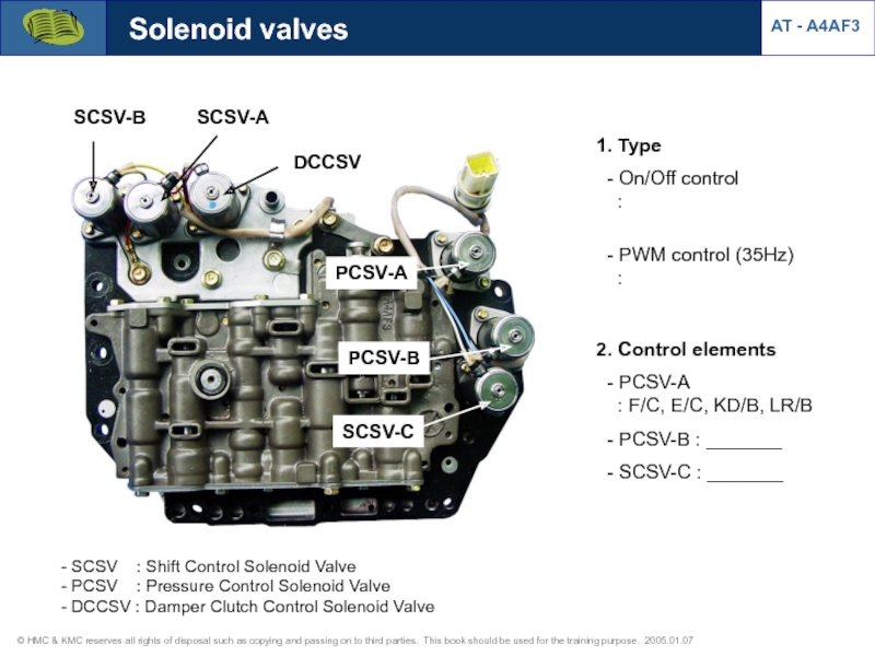
Слайд 681. Type
- On/Off control
:
- PWM control
- PCSV-A : F/C, E/C, KD/B, LR/B
- PCSV-B : _______
- SCSV-C : _______
DCCSV
SCSV-B
SCSV-A
PCSV-A
PCSV-B
SCSV-C
Solenoid valves
SCSV : Shift Control Solenoid Valve
PCSV : Pressure Control Solenoid Valve
DCCSV : Damper Clutch Control Solenoid Valve
AT - A4AF3
Слайд 69Solenoid valves
Operation table at D range (SCSV-A,B,C)
Solenoid resistance
DCCSV
SCSV-B
SCSV-A
PCSV-A
PCSV-B
SCSV-C
AT - A4AF3
Слайд 70Solenoid valves
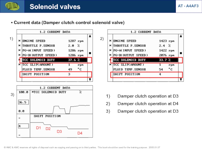
Current data (Damper clutch control solenoid valve)
D1
D2
D3
D4
Damper clutch operation
Damper clutch operation at D4
Damper clutch operation at D3
1)
2)
3)
AT - A4AF3
Слайд 71Solenoid valves
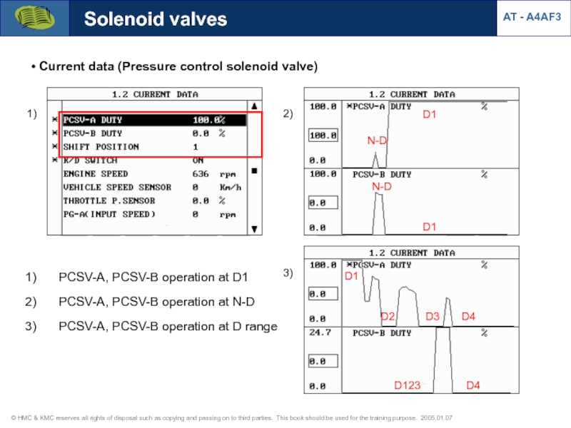
Current data (Pressure control solenoid valve)
N-D
D1
D1
N-D
D1
D2
D3
D4
D4
D123
1)
2)
PCSV-A, PCSV-B operation at
PCSV-A, PCSV-B operation at N-D
PCSV-A, PCSV-B operation at D range
3)
AT - A4AF3
Слайд 72Solenoid valves
Current data (Shift control solenoid valve)
SCSV-A, operation at D
SCSV-B, operation at D range
SCSV-C, operation at D range
1)
2)
3)
AT - A4AF3
ON (D12)
OFF (D34)
ON (D1)
ON (D4)
OFF (D23)
OFF (D12)
ON (D34)
3rd gear
4th gear
3rd ? 4th
Слайд 78Diagnosis (CAN BUS OFF Error)
AT - A4AF3
CAN BUS OFF Error
1) CAN-Low short to GND : DTC is not detected CAN communication with Scan tool is normal Current data from engine is normal
2) CAN-Low short to B+ : Communication error with Hi-scan DTC (U0001) is memorized
3) CAN-High short to GND or B+ : Communication error with Hi-scan DTC (U0001) is memorized
CAN interface required system (for Hi-scan communication) : Engine, AT, Immobilizer, Code saving
K-line communication system (without CAN interface) : ABS, ESP, A/Bag, TPMS
Слайд 791. Verify complaint
3. Problem symptom confirmation
4. 1) Are there DTC ?
incorrect ?
5. 1) Does symptom
occur intermittently ?
2) Does the big shock
happen ?
6. Electrical problem
7. Electrical
8. Hydraulic problem
9. Mechanical
10. Hydraulic
2. Basic inspection
No
Yes
No
Yes
Troubleshooting chart
AT - A4AF3
Слайд 806. Electrical problem
7. Electrical
8. Hydraulic problem
9. Mechanical
10. Hydraulic
DTC chart,
Actuator test
Driving test for flight record
Oil passage or valve body clean and check
Stall test
Hydraulic test
11. Identification of problem
12. Repair
13. Confirmation test
14. END
Troubleshooting chart
AT - A4AF3
Слайд 82AT - A4AF3
Stall test
Shift range for stall test : D(1,3), L(1),
Preparation - ATF temperature : 80 ~ 90 ℃ - Fluid level : at ‘HOT’ mark on the oil level gauge - Apply chocks to both rear wheels (or jack up the vehicle) - Connect Hi-scan pro and read ‘Engine speed’
Stall RPM : 2400 ~ 2800 rpm
Test result
Слайд 83Pressure test
Pressure test range : D/2/L/R
Preparation
- Warm up the engine and
Standard value : Refer to workshop manual
AT - A4AF3
09452-2150
09452-21001
09452-21002
Слайд 84Pressure test
Pressure ports
AT - A4AF3
Reducing pressure
Kickdown wervo pressure
Rear clutch pressure
Front clutch
End clutch pressure
Low & reverse brake pressure
Damper clutch apply pressure
Damper clutch release pressure
Слайд 86AT Tester with adapter cables for AT (F4A**, F4EL-K, AISIN)
Pressure test
AT - A4AF3
Слайд 87Pressure sensor installation with AT Tester
AT - A4AF3
[AT Tester]
[Pressure control box]
[Pressure
Pressure test (Preparation)
Слайд 89[R/C pressure & PCSV-B operation at N?D?N]
Pressure test
1) Rear clutch pressure
Rear
N?D
D?N
Duty controlled
2.7V = 8.2kg/cm2
[R/C pressure & SCSV-A operation at N?D?N]
N?D
D?N
OFF
ON
AT - A4AF3
Слайд 90AT - A4AF3
Pressure test
1) Rear clutch pressure
N?D?2
L range, idle
[R/C pressure at
[R/C pressure at L]
R/C pressure at L
PCSV-A duty control
Слайд 91Pressure test
Damper clutch pressure (Waveform from pressure sensor)
[At P,N range]
[At R
D/R pressure (1.1V=4.5kg/cm2)
D/A pressure (0.95V = 3.5kg/cm2)
D/A: Damper clutch apply
D/R: Damper clutch release
D/R pressure
D/A pressure
During acceleration
AT - A4AF3
Слайд 92Damper clutch pressure
Pressure test
[At D range]
Damper clutch pressure (Waveform from pressure
D/R pressure
D/A pressure
a
b
c
d
* a : D 1,2,3 gear
b: D 3 gear with damper clutch engaged (lock-up)
c: D3-4 up shift (no lock-up)
d: D4 gear with lock-up
d
a
b
c
2~3.5 kg/cm2
AT - A4AF3
Слайд 93Pressure test
[At 2 range]
[At L range]
Damper clutch pressure (Waveform from pressure
D/R pressure
D/A pressure
a
b
D/R pressure
D/A pressure
* a : 2 range 1,2 gear
b: 2 range 2 gear with lock-up
2~3.5 kg/cm2
AT - A4AF3
Слайд 94Pressure test
Kick down servo apply pressure (Waveform from pressure sensor)
[At N-D
D range
N range
[At D range]
Servo apply pressure
D1
6.5 kg/cm2
D4
D3
8.5 kg/cm2
7 kg/cm2
SCSV-A
D1(ON)
D23(OFF)
D4(ON)
D2
AT - A4AF3
Слайд 95Kick down servo apply pressure (Waveform from pressure sensor)
Pressure test
2-2 (Servo
8.5 kg/cm2
SCSV-A
2-1(ON)
2-2(OFF)
[At 2 range]
AT - A4AF3
Слайд 96L&R brake pressure (Waveform from pressure sensor)
Pressure test
[At R range]
N?R
[At L
12 kg/cm2
a: PCSV-A duty control
b: PCSV-A duty 0% (accleration)
a
b
Acceleration
17 kg/cm2
2 ? L
4~6 kg/cm2
Acceleration
PCSV-A duty control (32%)
AT - A4AF3
Слайд 97L&R brake stall pressure
Pressure test
[R range stall pressure]
[At L range stall
N?R
20 kg/cm2
a
a: Stall test range
4~6 kg/cm2
a
AT - A4AF3








![Brake switchAT - A4AF3[Brake switch signal]Brake appliedHigh :12VLow : 0VPurpose Damper cltuch operation (brake applied](/img/tmb/6/513692/01f25eedaa89ab91f46dc4b54210c49c-800x.jpg)
![Oil temperature sensor[Valve body]Oil temperature sensor Pressure control : PCSV duty changes according to](/img/tmb/6/513692/5e671f21512d53dcbb1c875932b60cbc-800x.jpg)
![Diangosis (oil temperature sensor)* Oil temperature sensorAT - A4AF3[Oil temperature-circuit open][DTC-circuit open][Oil temperature-failsafe]](/img/tmb/6/513692/fbb490ca30de5bf8eadccb828e43bac2-800x.jpg)
![Dashboard range signalAT - A4AF3ClusterInhibitor switchPRNDPCM2LDashboard range signal(2, L, PWM)[Trip computer display on the clutster]](/img/tmb/6/513692/9495041aec65b269d77359c1fa1b6b15-800x.jpg)



![Solenoid valves Circuit diagram[DCCSV duty signal][PCSV-A duty signal-duty 100%]AT - A4AF3](/img/tmb/6/513692/559e4f084b2678b8cb5a9135ff16b3f2-800x.jpg)
![Diagnosis (solenoid valves)[Failsafe: 3rd gear hold at D,2,L]AT - A4AF3](/img/tmb/6/513692/f8b8b79bf99b08ce44286378b40661c4-800x.jpg)



![Pressure sensor installation with AT TesterAT - A4AF3[AT Tester][Pressure control box][Pressure sensor & adapter]Pressure test (Preparation)](/img/tmb/6/513692/8e6adfb47373e1be466aa35cfa09a40f-800x.jpg)
![[R/C pressure & PCSV-B operation at N?D?N]Pressure test1) Rear clutch pressureRear clutch pressureN?DD?NDuty controlled2.7V =](/img/tmb/6/513692/6db4fb7c6ed9013b95df95e238a98427-800x.jpg)
![AT - A4AF3Pressure test1) Rear clutch pressureN?D?2L range, idle[R/C pressure at N?D?2?L][R/C pressure at L]R/C](/img/tmb/6/513692/f9eb1741f53cfdb9c679f8ba544f5409-800x.jpg)
![Pressure testDamper clutch pressure (Waveform from pressure sensor)[At P,N range][At R range]D/R pressure (1.1V=4.5kg/cm2)D/A pressure](/img/tmb/6/513692/88488cc238c16ec79a9ad9fd39d3728b-800x.jpg)
![Damper clutch pressurePressure test[At D range]Damper clutch pressure (Waveform from pressure sensor)D/R pressureD/A pressureabcd* a](/img/tmb/6/513692/345a275f7bbafb6f419d50b220678000-800x.jpg)
![Pressure test[At 2 range][At L range]Damper clutch pressure (Waveform from pressure sensor)D/R pressureD/A pressureabD/R pressureD/A](/img/tmb/6/513692/92ef4b794bb69ee3191d46a86a94aec9-800x.jpg)
![Pressure testKick down servo apply pressure (Waveform from pressure sensor)[At N-D control]D rangeN range[At D](/img/tmb/6/513692/cb589671de208a82c7e4b5b85e408183-800x.jpg)
![L&R brake pressure (Waveform from pressure sensor)Pressure test[At R range]N?R[At L range]12 kg/cm2a: PCSV-A duty](/img/tmb/6/513692/40ca799b36218535789d7773f8633437-800x.jpg)
![L&R brake stall pressurePressure test[R range stall pressure][At L range stall pressure]N?R20 kg/cm2aa: Stall test](/img/tmb/6/513692/6f35d5244d1387ce37902817fad0a453-800x.jpg)

