- Главная
- Разное
- Дизайн
- Бизнес и предпринимательство
- Аналитика
- Образование
- Развлечения
- Красота и здоровье
- Финансы
- Государство
- Путешествия
- Спорт
- Недвижимость
- Армия
- Графика
- Культурология
- Еда и кулинария
- Лингвистика
- Английский язык
- Астрономия
- Алгебра
- Биология
- География
- Детские презентации
- Информатика
- История
- Литература
- Маркетинг
- Математика
- Медицина
- Менеджмент
- Музыка
- МХК
- Немецкий язык
- ОБЖ
- Обществознание
- Окружающий мир
- Педагогика
- Русский язык
- Технология
- Физика
- Философия
- Химия
- Шаблоны, картинки для презентаций
- Экология
- Экономика
- Юриспруденция
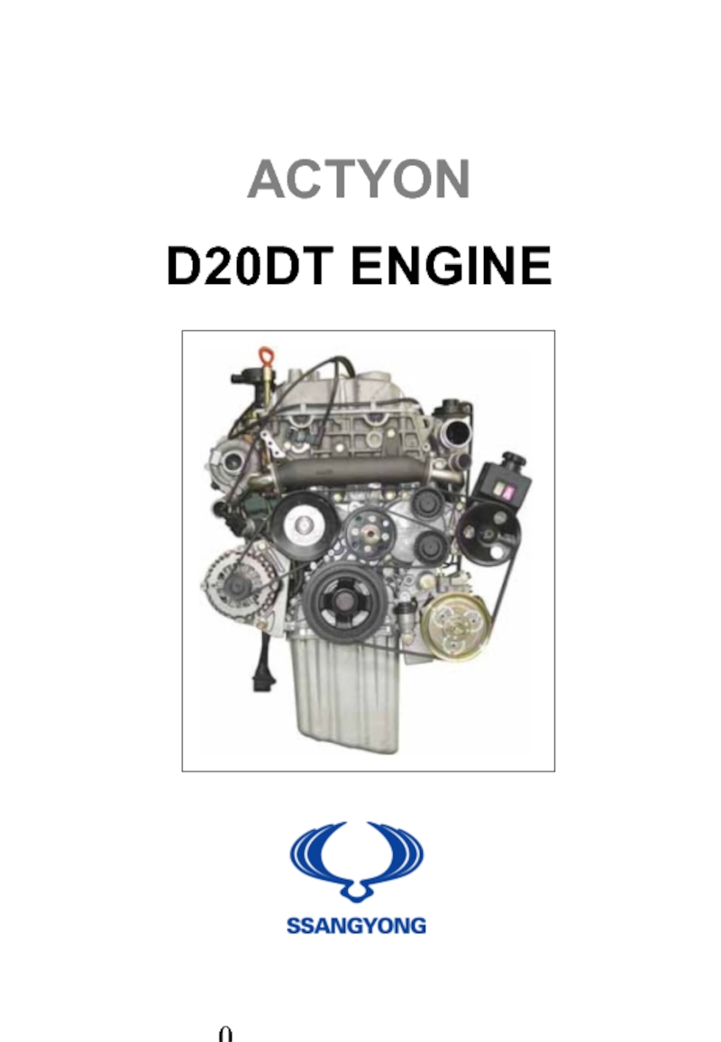
Actyon D20DT Engine презентация
Содержание
- 1. Actyon D20DT Engine
- 3. Contents Chapter 1. D20DT
- 4. 3. VGT Non-Operating Conditions -------------------------------------------------
- 5. Chapter 1 D20DT Engine General
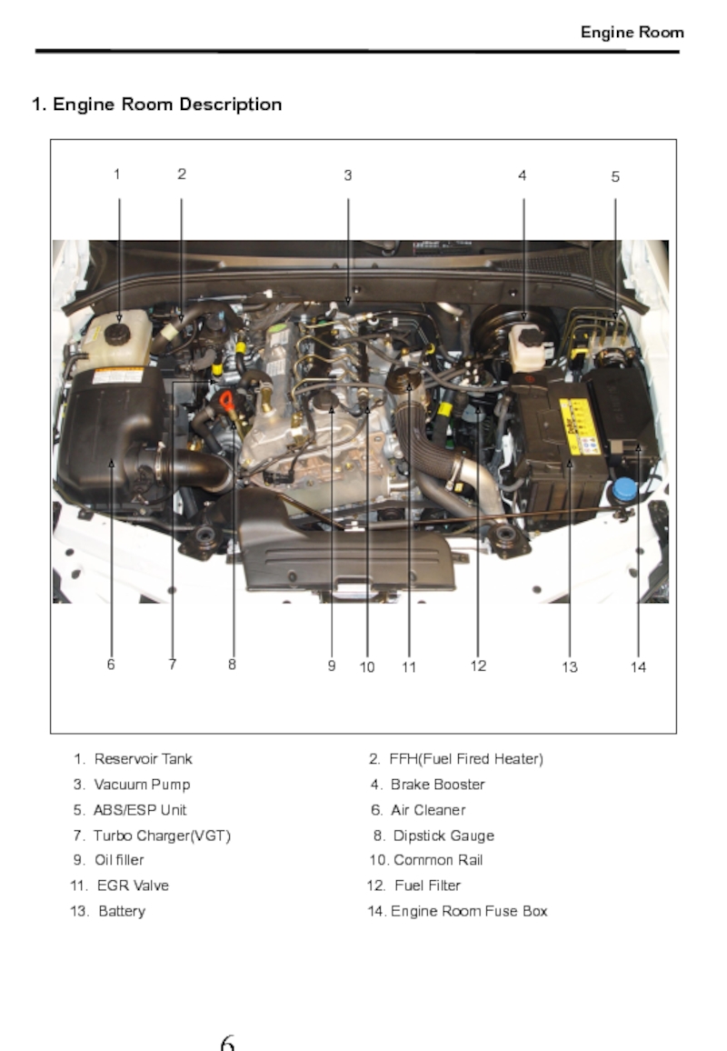
- 7. 1. Engine Room Description 1 2
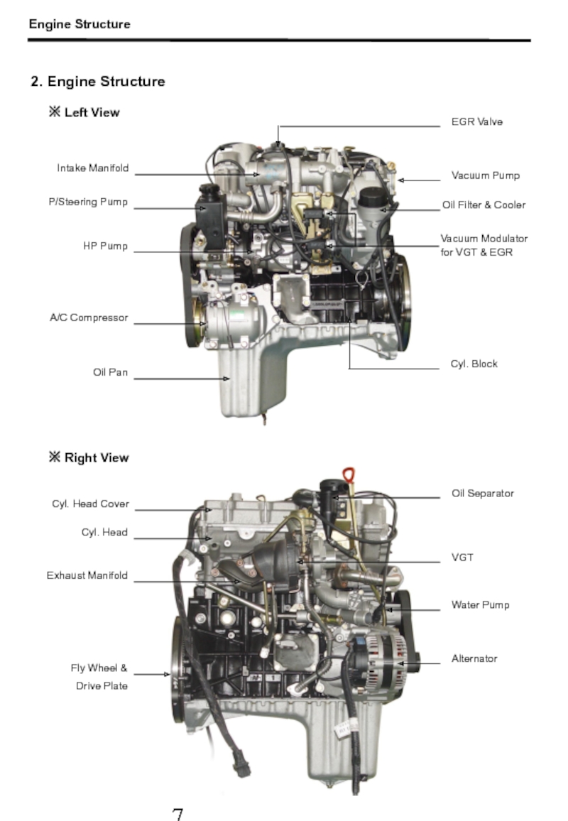
- 8. 2. Engine Structure ※ Left View Intake
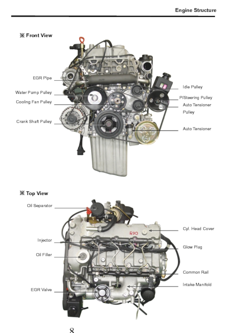
- 9. ※ Front View ※ Top View Oil
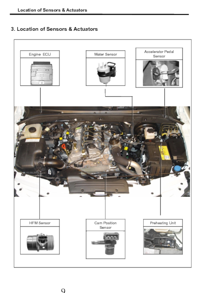
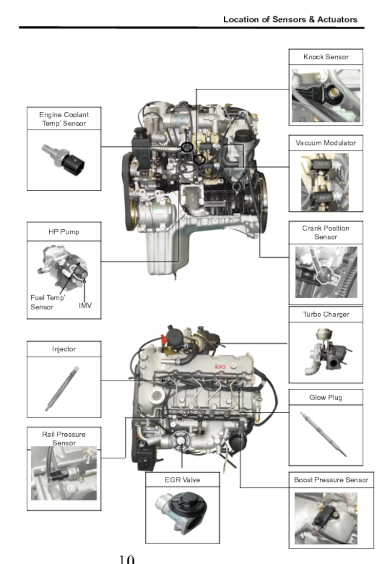
- 10. 3. Location of Sensors & Actuators Location of Sensors & Actuators
- 11. Fuel Temp’ Sensor IMV Location of Sensors & Actuators
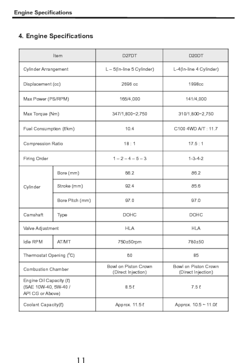
- 12. 4. Engine Specifications Engine Specifications
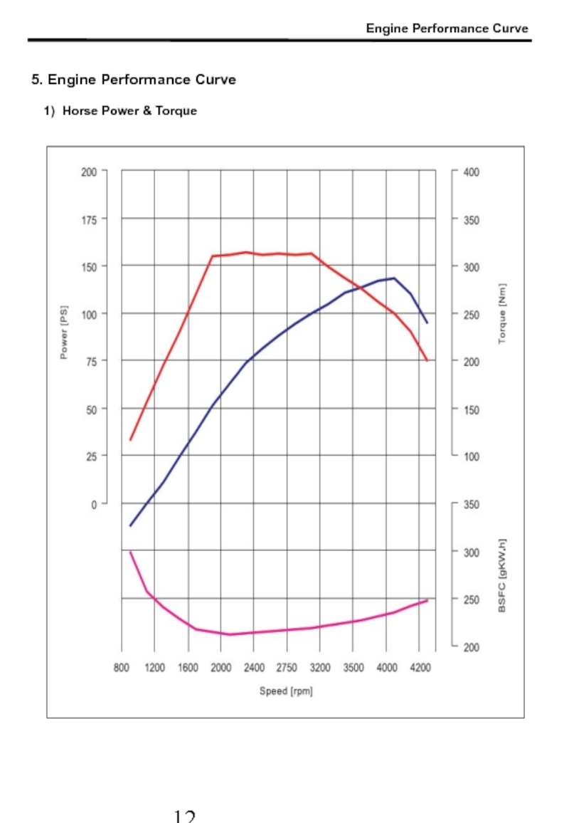
- 13. 5. Engine Performance Curve 1) Horse Power & Torque Engine Performance Curve
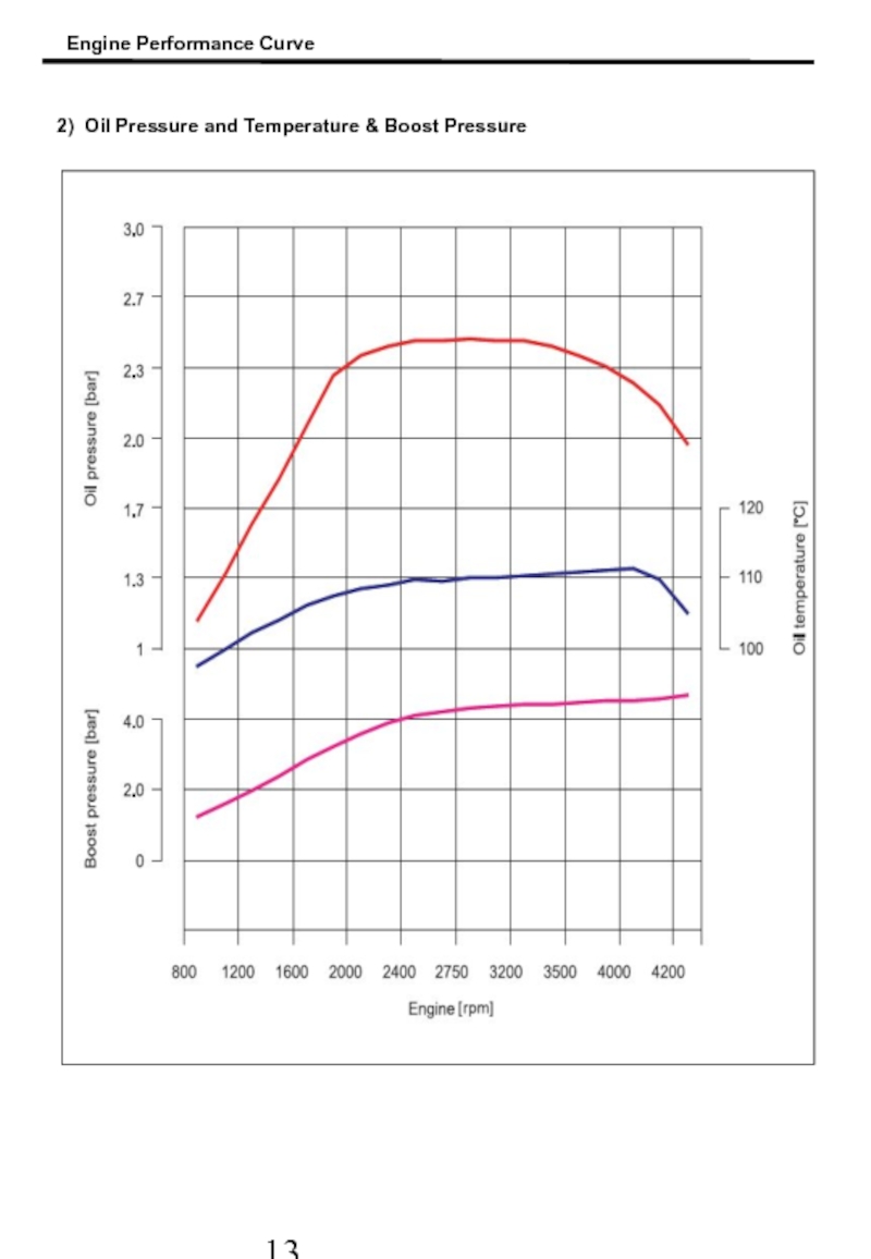
- 14. 2) Oil Pressure and Temperature & Boost Pressure Engine Performance Curve
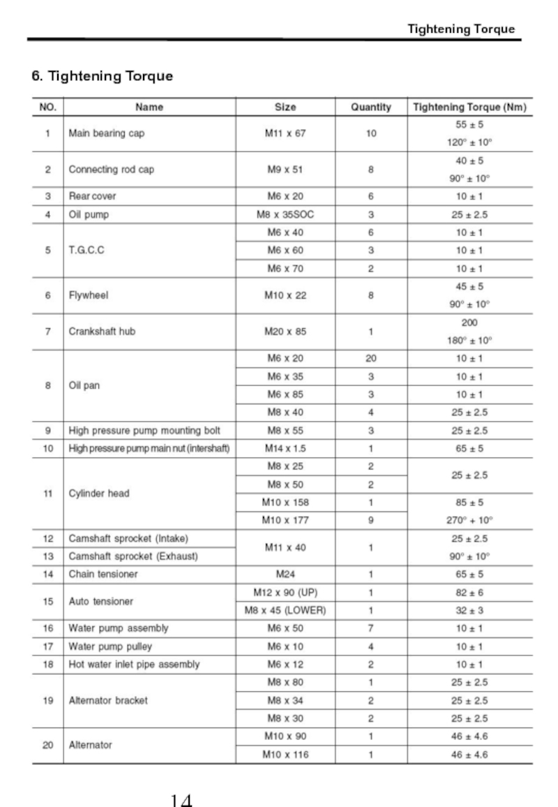
- 15. 6. Tightening Torque Tightening Torque
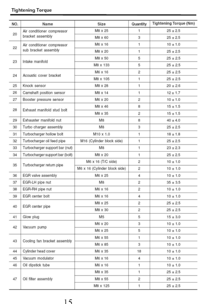
- 16. Tightening Torque
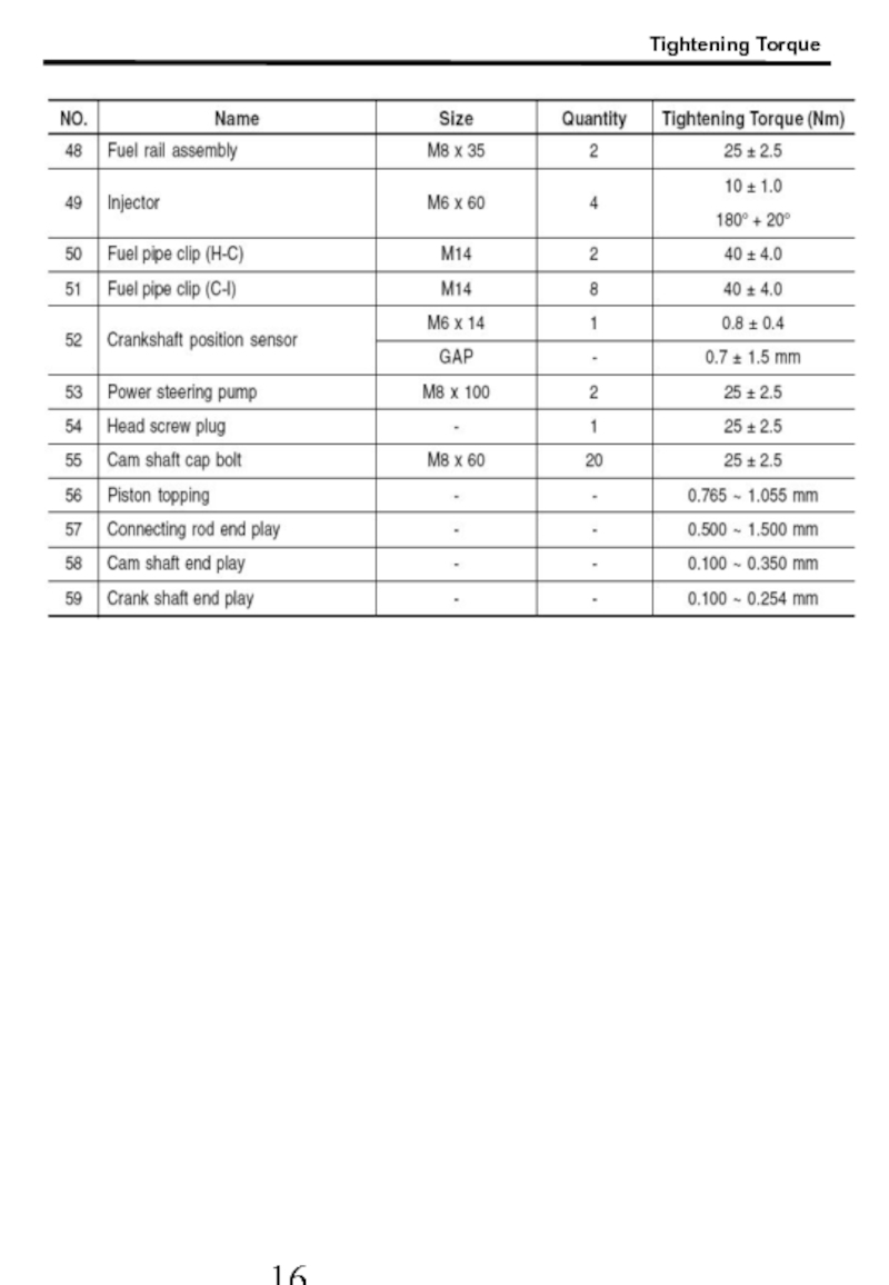
- 17. Tightening Torque
- 18. HP Pipe (Common Rail ? Injector) :
- 19. Tightening Torque 2) HP Pump System Tightening
- 21. Chapter 2 Removal & Installation
- 23. Components and Special Tools 1. Components and Special Tools
- 24. Components and Special Tools
- 25. Components and Special Tools 1. List for Special Tools
- 26. 1. Turn the auto tensioner counterclockwise
- 27. 5. Align the OT mark by rotating
- 28. 9. Slacken three HP pump mounting bolts
- 29. 2. Tighten the HP pump bolts.
- 30. 6. Install auto tensioner and belt pulley.
- 31. ① When installing/removing of chain or sprocket,
- 32. 4. Glow plug distinction When replacing one
- 33. D20DT D27DT
- 34. D20DT D27DT D20DT D27DT #1 #2 #3 #4 #1 #2 #3 #4 #5 Major Difference
- 35. Major Difference Max 7.5L
- 37. Chapter 3 Turbo Charger (VGT)
- 39. Turbo Charger Turbo charger increases the amount
- 40. 2. VGT Principle (Variable Geometry Turbocharger) The
- 41. This represents that how much the ECU
- 42. [ VGT Actuator Duty Value (%) ]
- 43. ① Be sure not to transmit external
- 44. ④ The screw for adjusting of actuator
- 45. 6. Turbo Charger Troubleshooting Turbo charger trouble
- 47. Chapter 4 Diagnosis
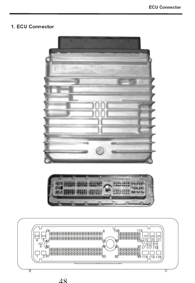
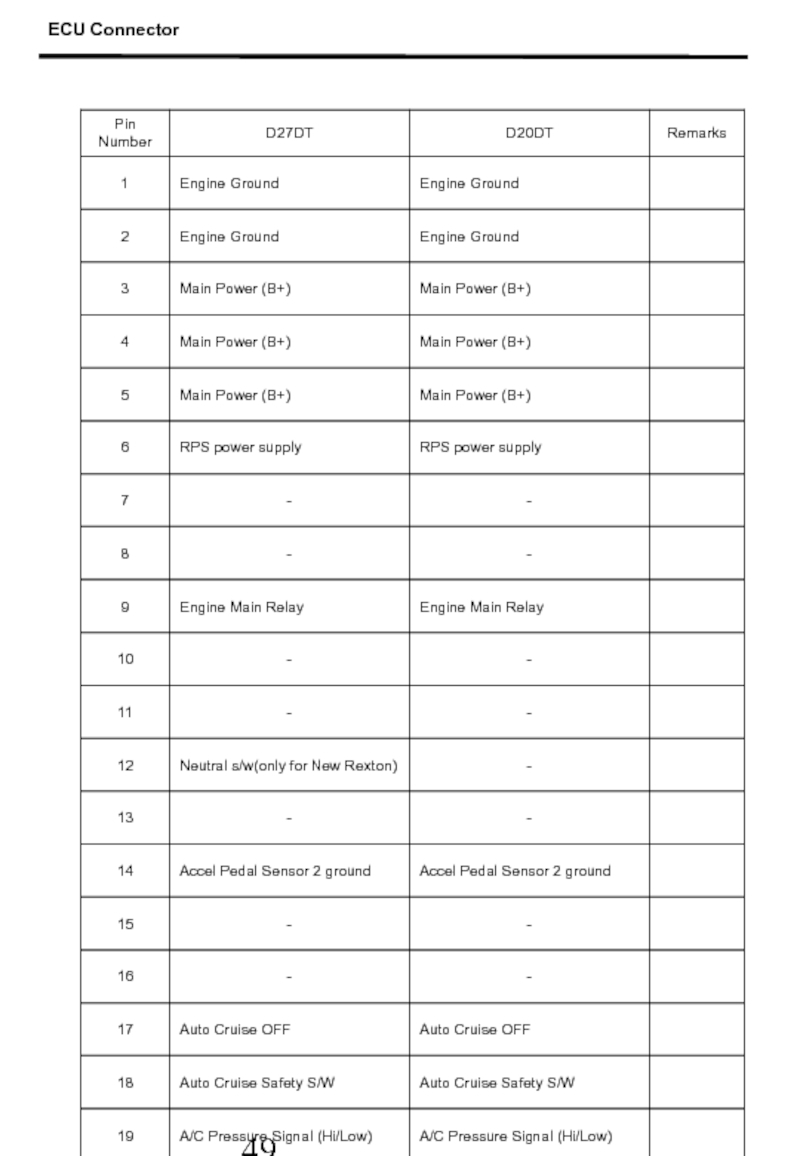
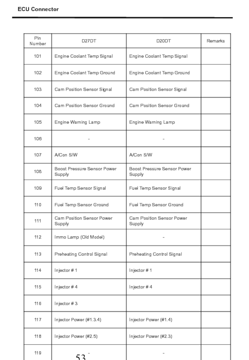
- 49. 1. ECU Connector ECU Connector
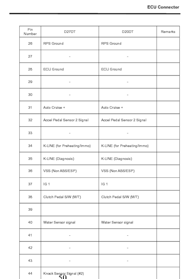
- 50. ECU Connector
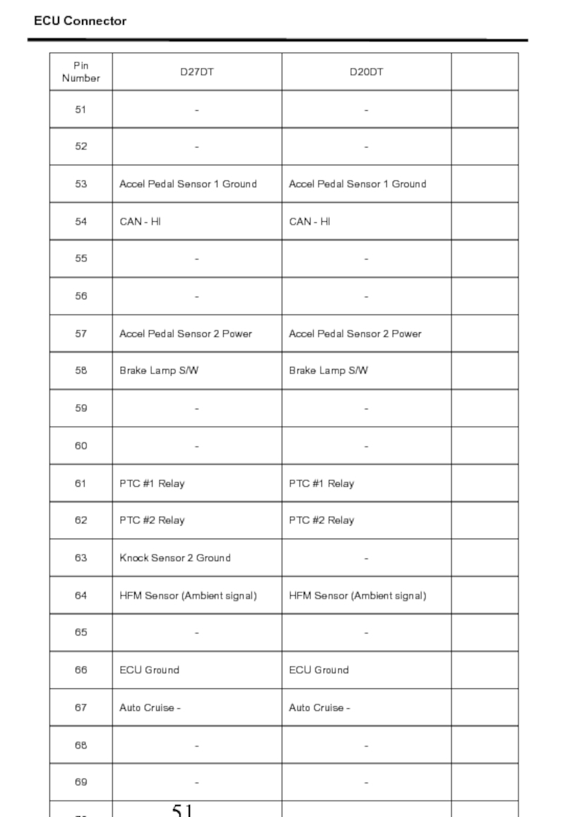
- 51. ECU Connector
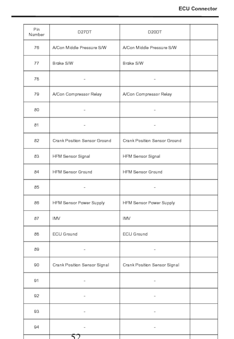
- 52. ECU Connector
- 53. ECU Connector
- 54. ECU Connector
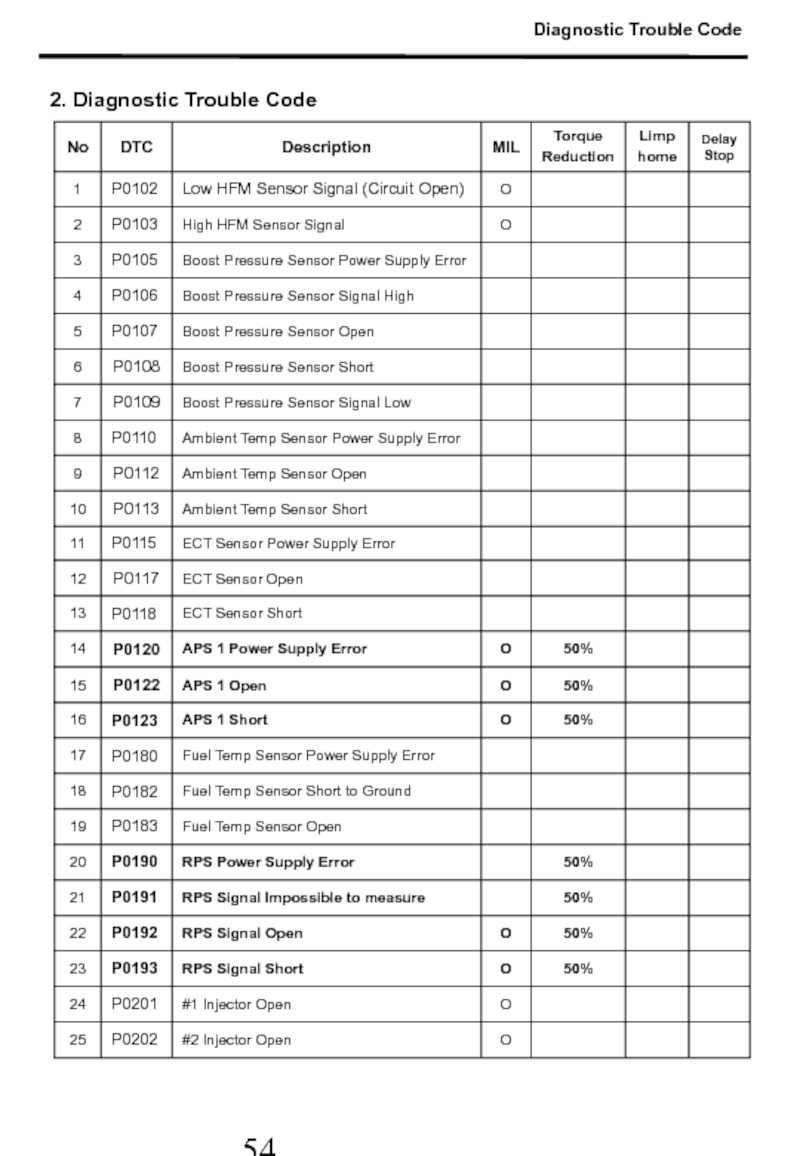
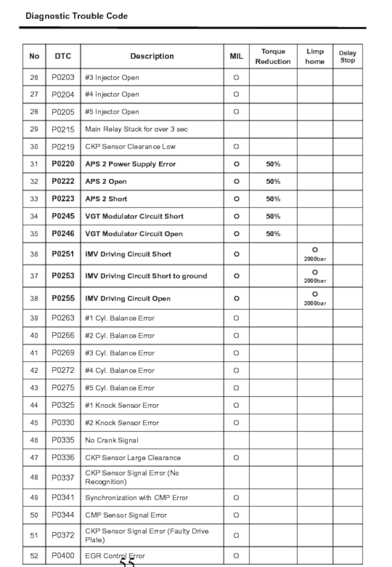
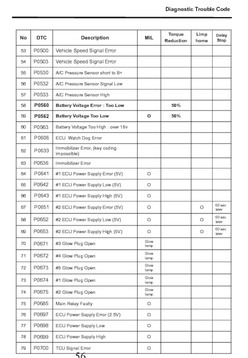
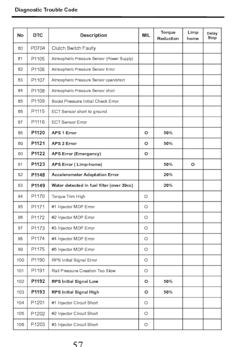
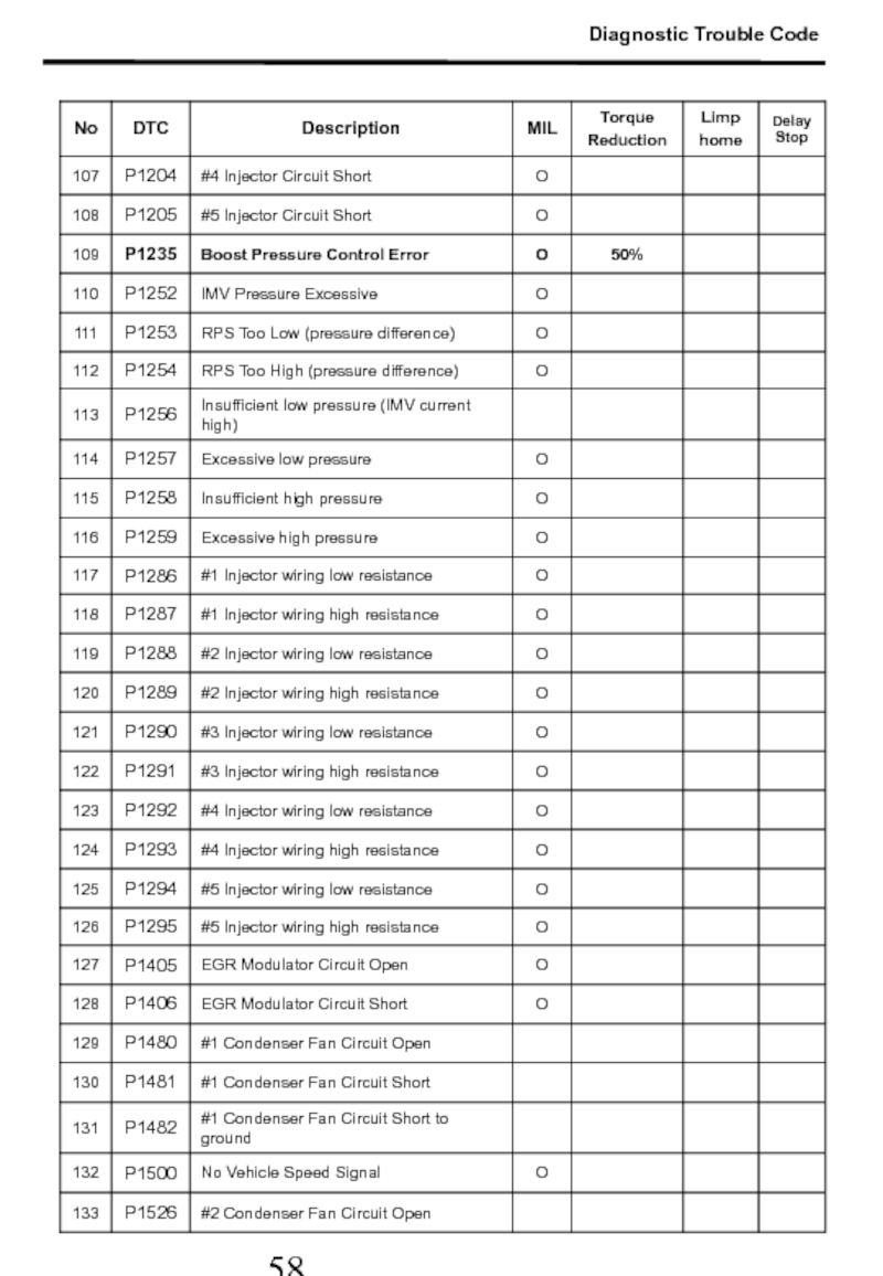
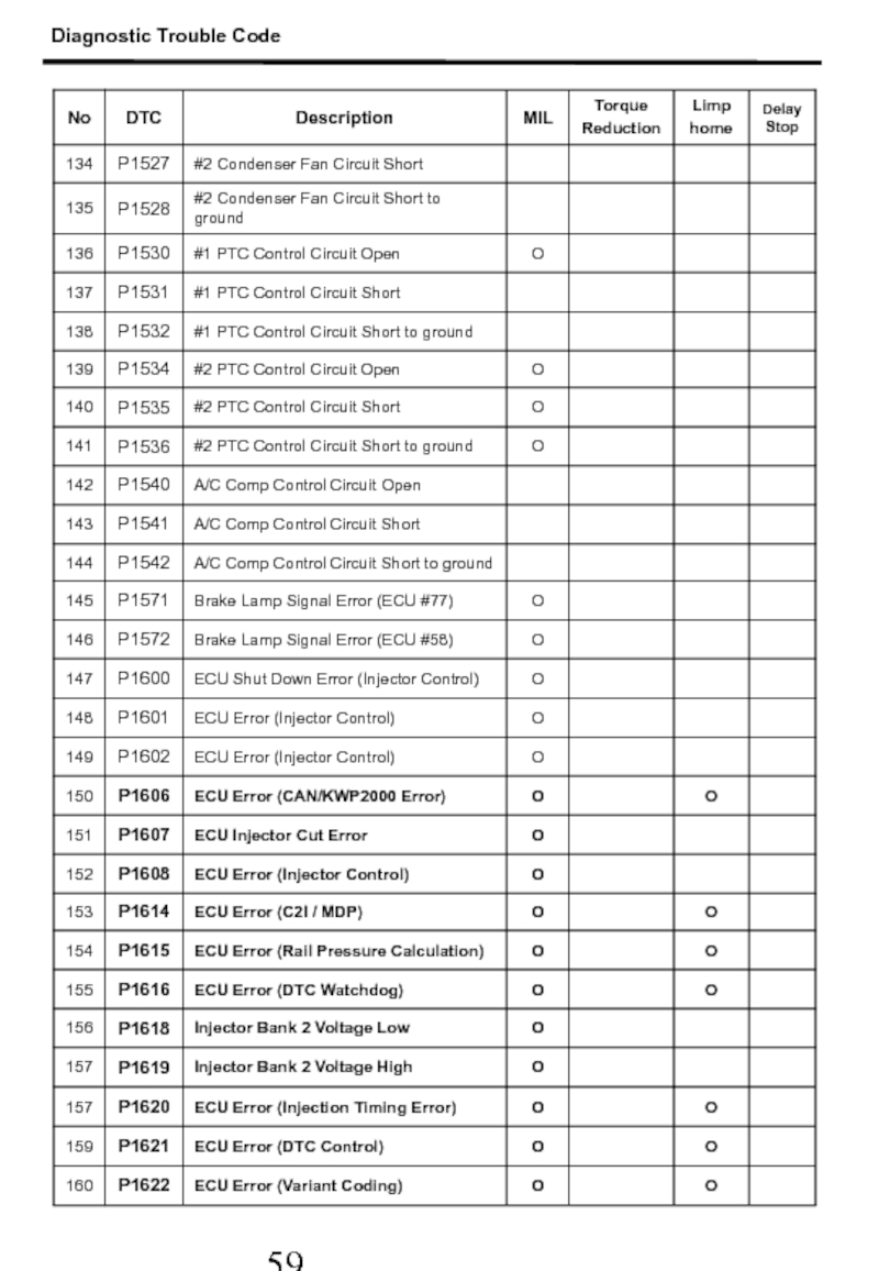
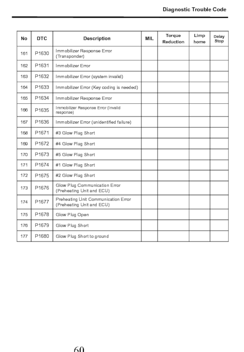
- 55. 2. Diagnostic Trouble Code Diagnostic Trouble Code
- 56. Diagnostic Trouble Code
- 57. Diagnostic Trouble Code
- 58. Diagnostic Trouble Code
- 59. Diagnostic Trouble Code
- 60. Diagnostic Trouble Code
- 61. Diagnostic Trouble Code
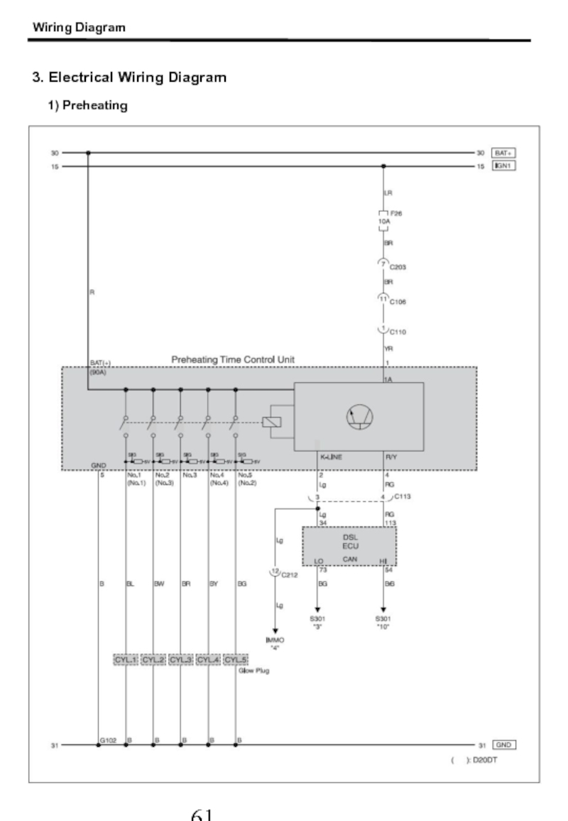
- 62. Wiring Diagram 3. Electrical Wiring Diagram 1) Preheating
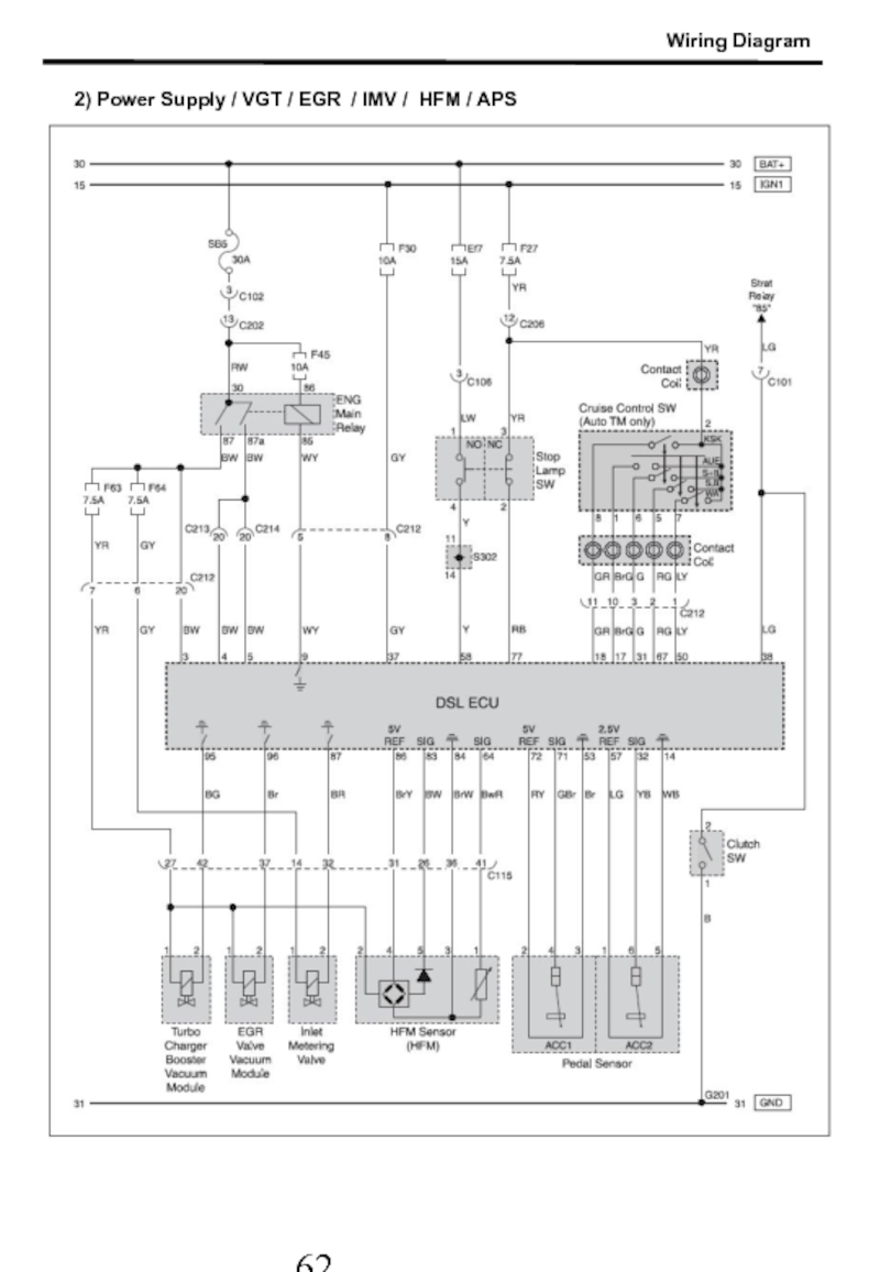
- 63. 2) Power Supply / VGT / EGR / IMV / HFM / APS Wiring Diagram
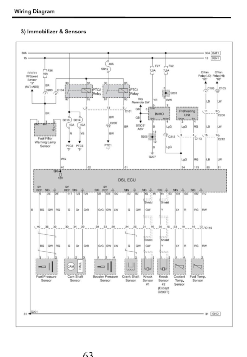
- 64. 3) Immobilizer & Sensors Wiring Diagram
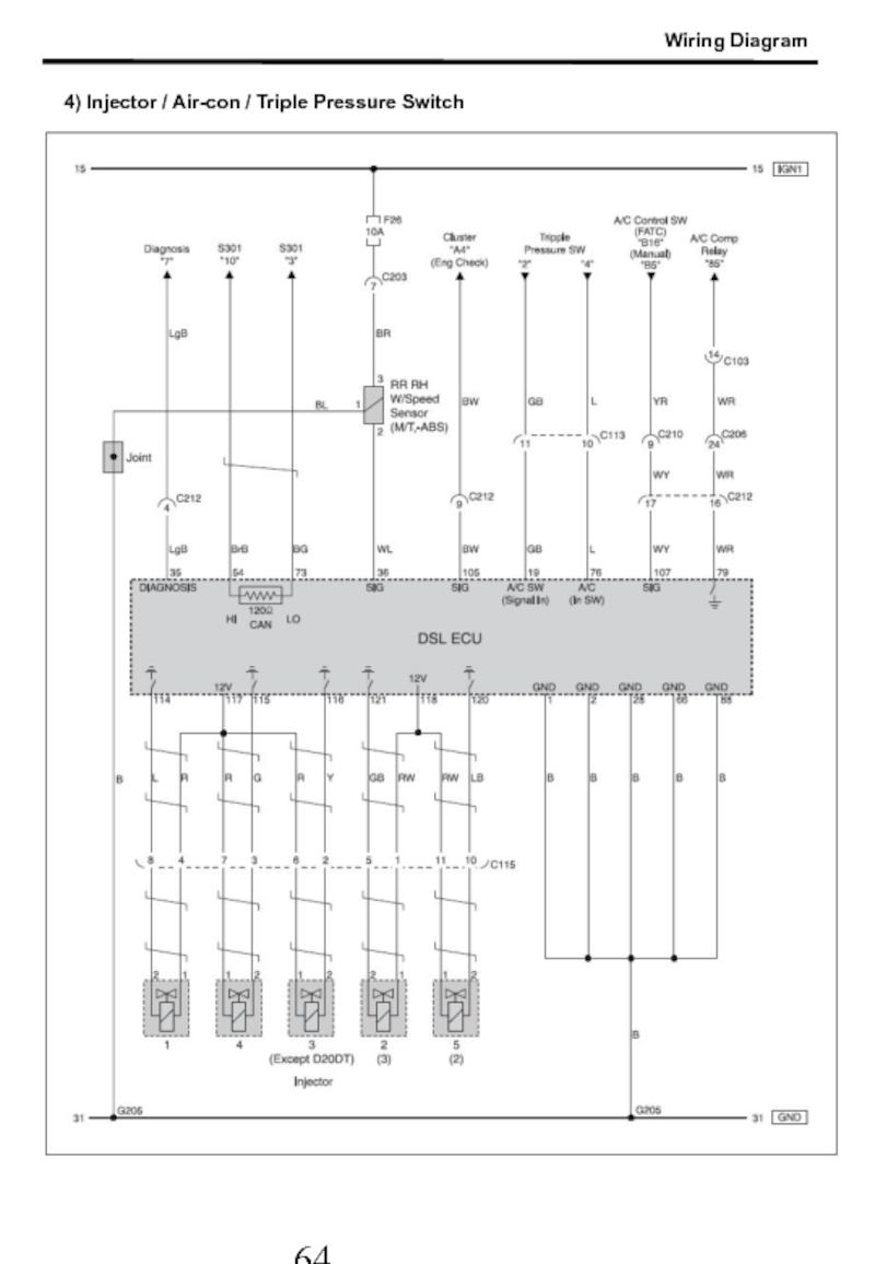
- 65. 4) Injector / Air-con / Triple Pressure Switch Wiring Diagram
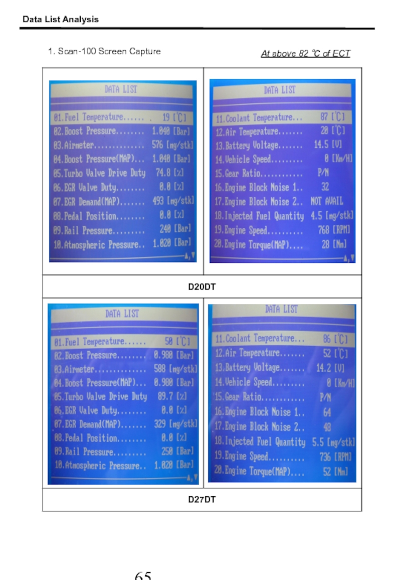
- 66. Data List Analysis 1. Scan-100 Screen Capture At above 82 ℃ of ECT
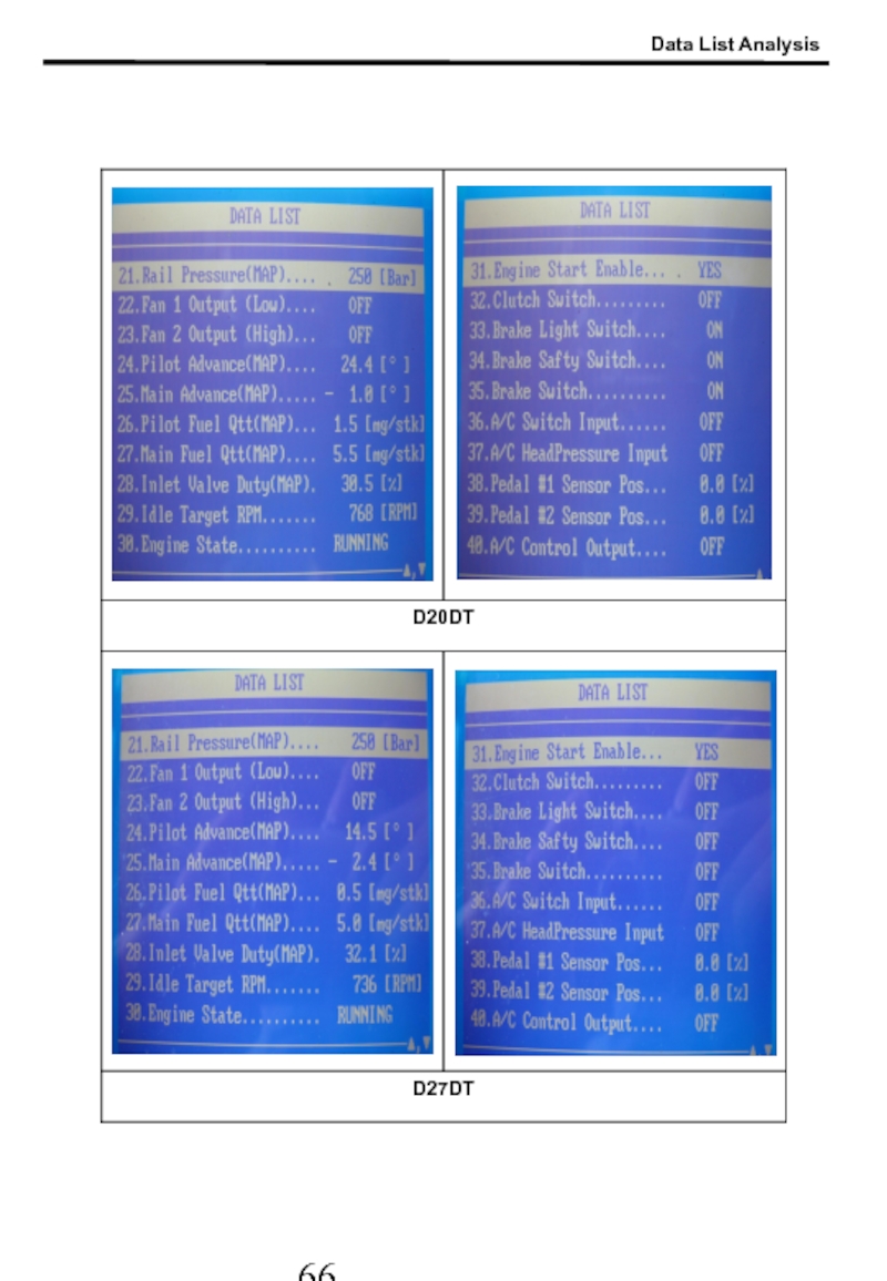
- 67. Data List Analysis
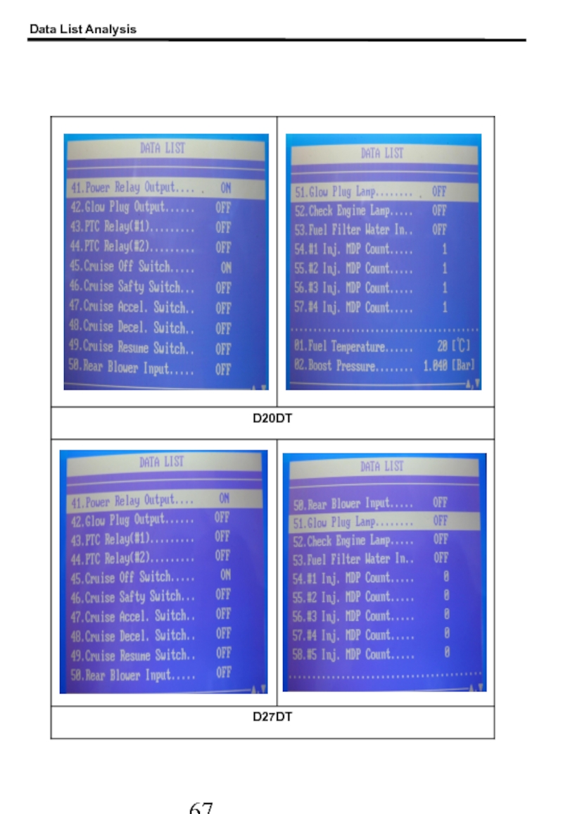
- 68. Data List Analysis
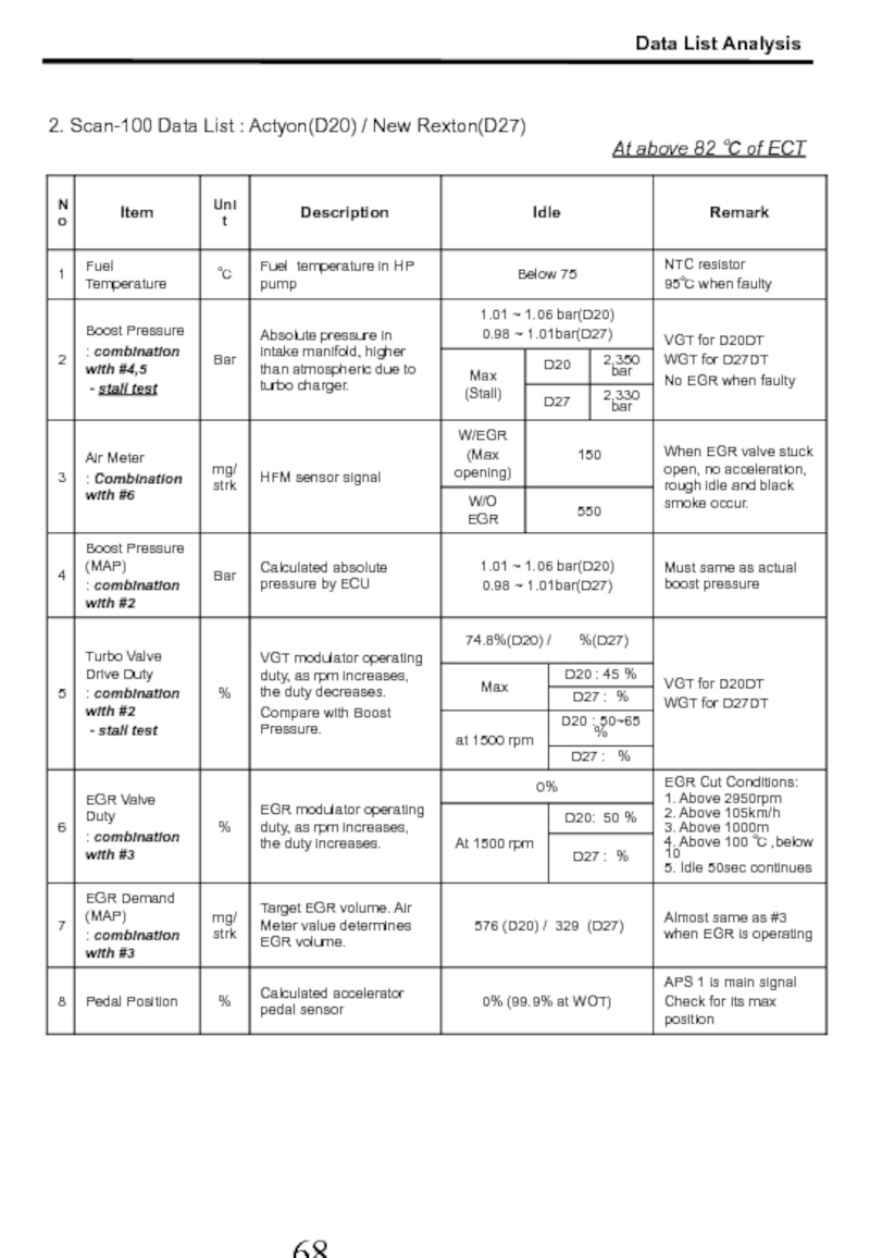
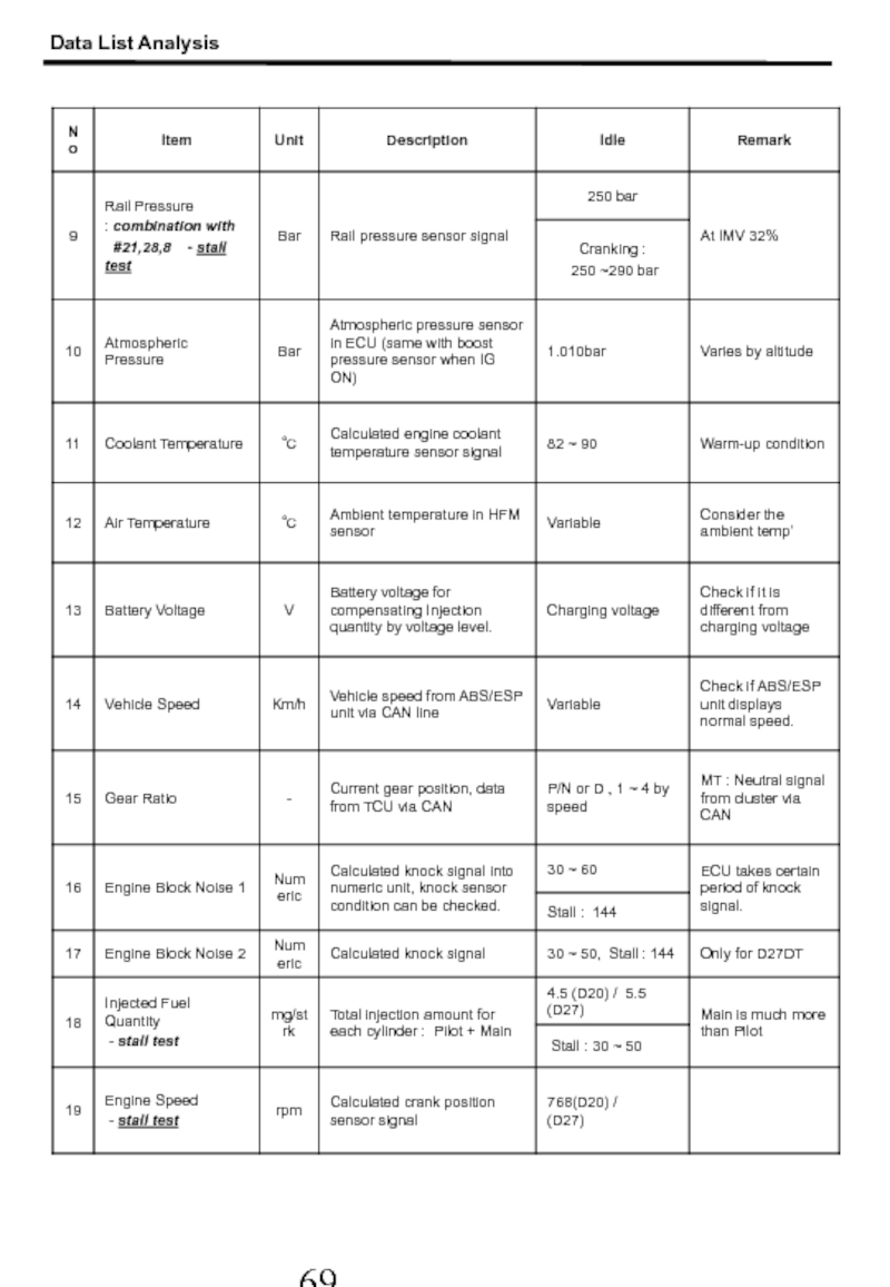
- 69. 2. Scan-100 Data List : Actyon(D20) /
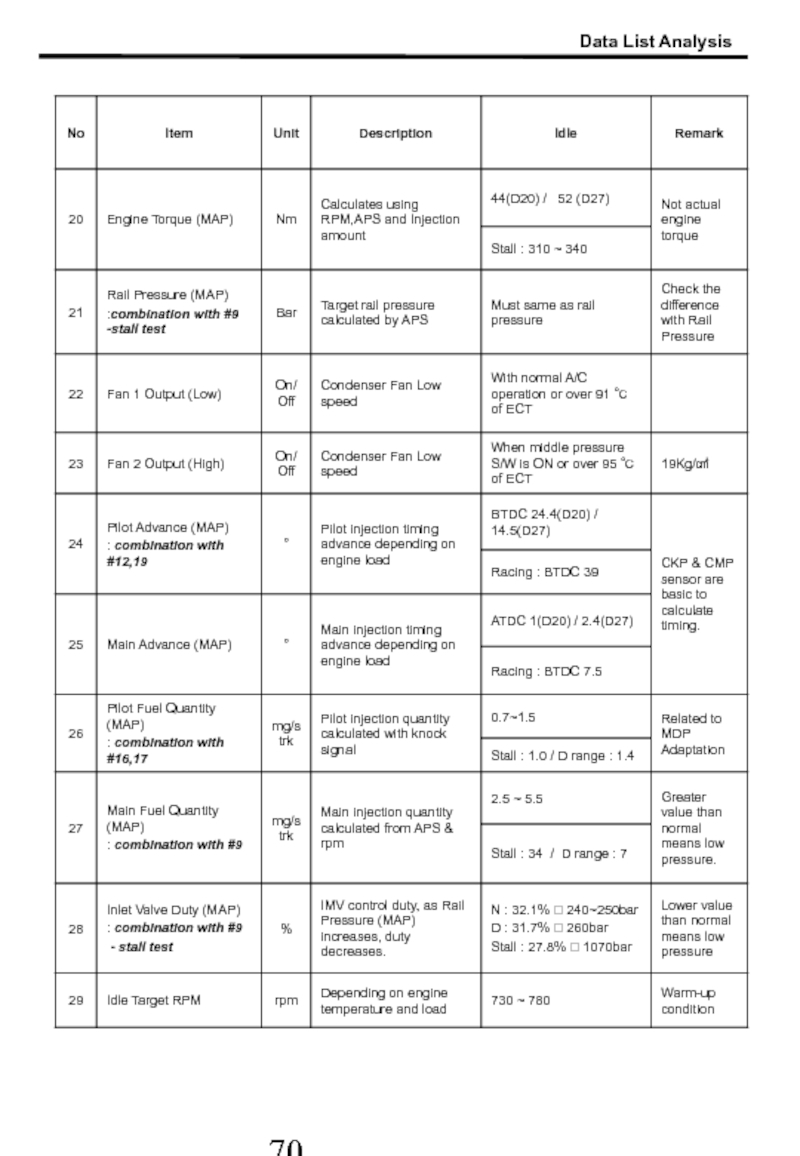
- 70. Data List Analysis
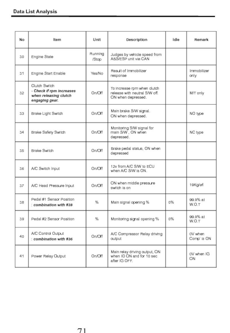
- 71. Data List Analysis
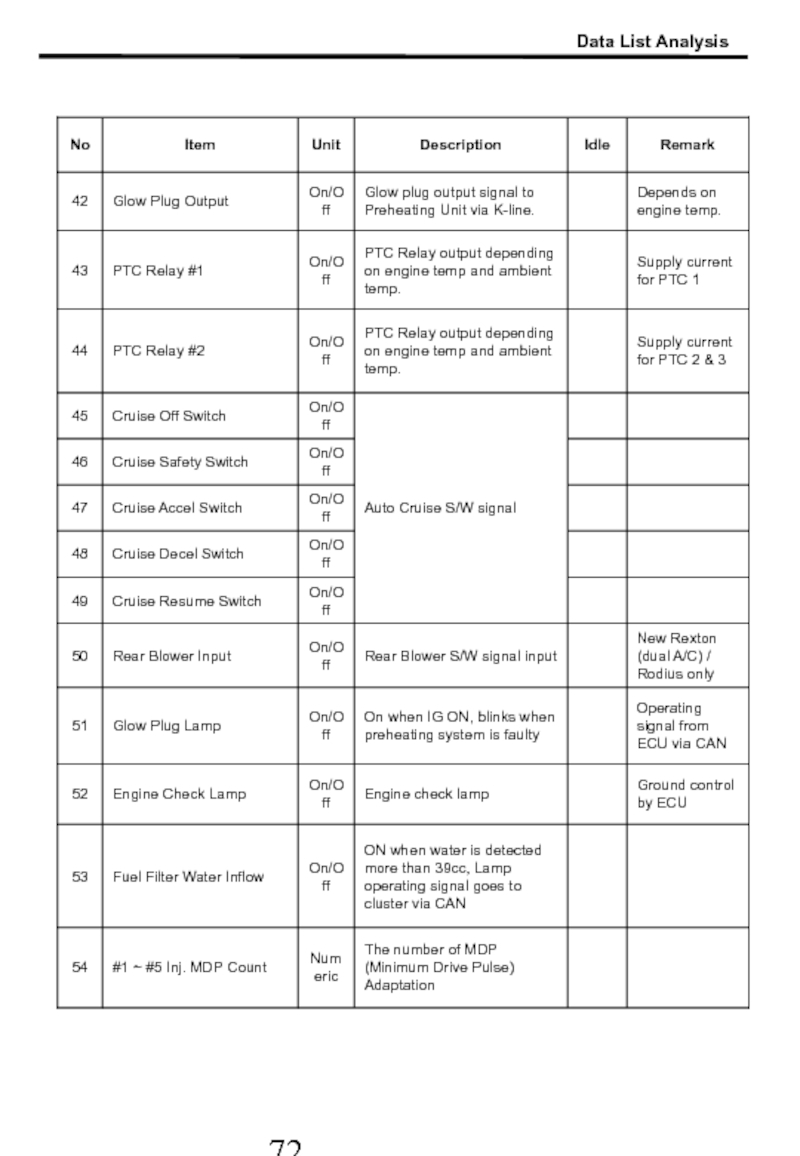
- 72. Data List Analysis
- 73. Data List Analysis
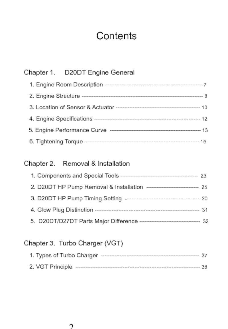
Слайд 3Contents
Chapter 1. D20DT Engine General
1. Engine Room
2. Engine Structure ------------------------------------------------------------------------ 8
3. Location of Sensor & Actuator -------------------------------------------------- 10
4. Engine Specifications --------------------------------------------------------------- 12
5. Engine Performance Curve ------------------------------------------------------ 13
6. Tightening Torque -------------------------------------------------------------------- 15
Chapter 2. Removal & Installation
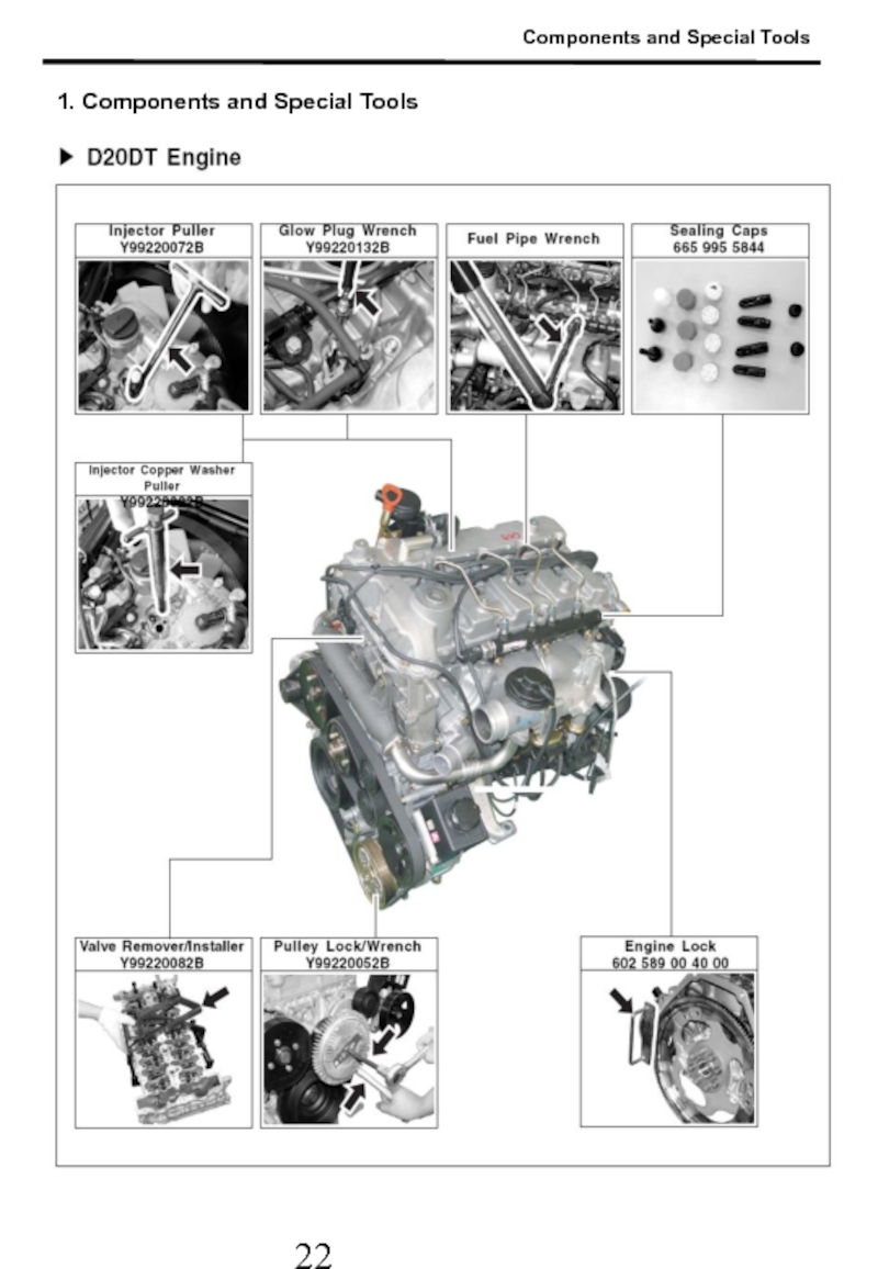
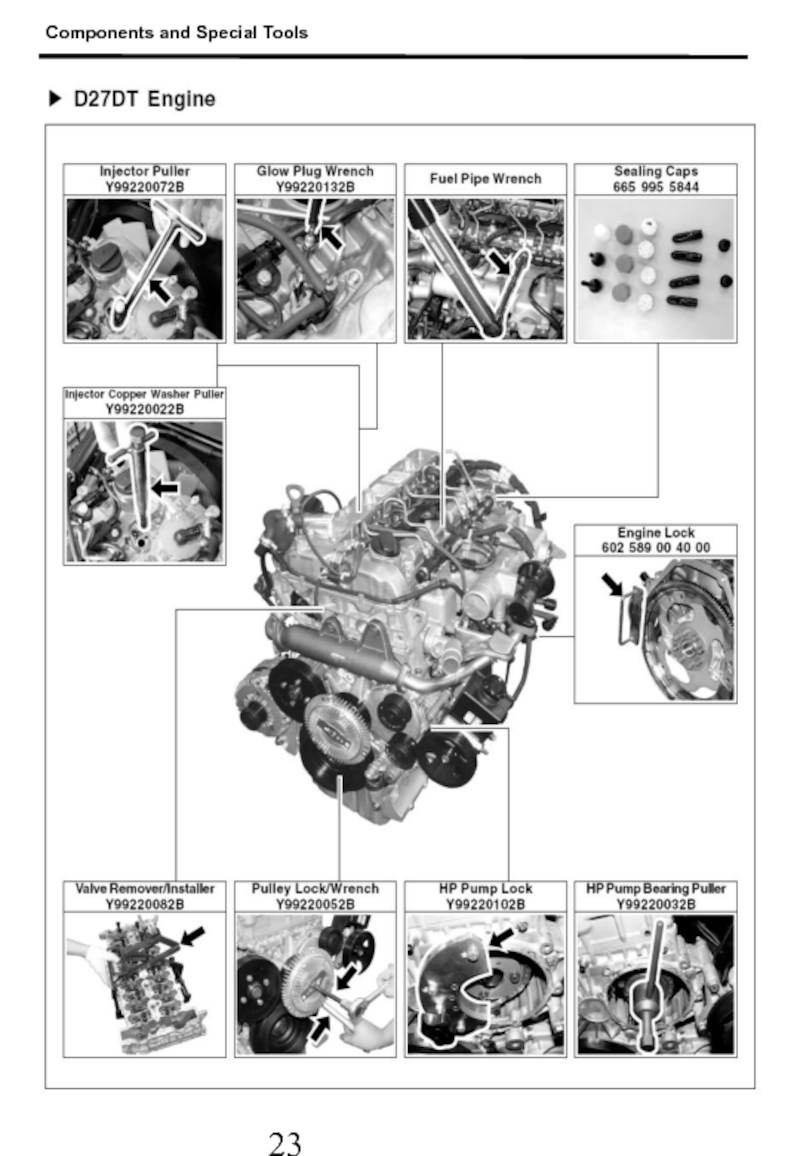
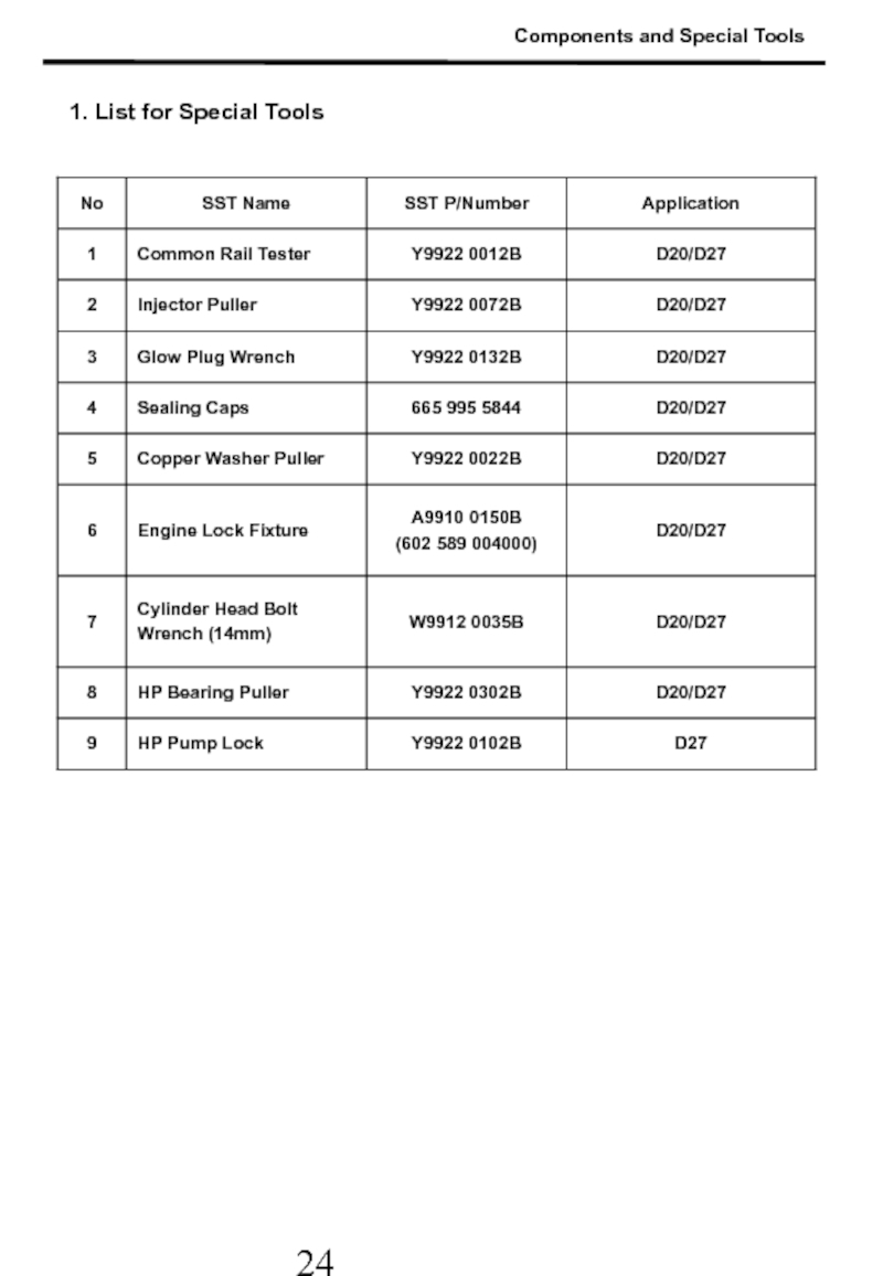
1. Components and Special Tools ---------------------------------------------- 23
2. D20DT HP Pump Removal & Installation ------------------------------- 25
3. D20DT HP Pump Timing Setting -------------------------------------------- 30
4. Glow Plug Distinction -------------------------------------------------------------- 31
5. D20DT/D27DT Parts Major Difference ------------------------------------ 32
Chapter 3. Turbo Charger (VGT)
1. Types of Turbo Charger ---------------------------------------------------------- 37
2. VGT Principle -------------------------------------------------------------------------- 38
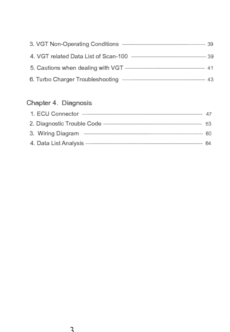
Слайд 4 3. VGT Non-Operating Conditions ------------------------------------------------- 39
4. VGT
5. Cautions when dealing with VGT ----------------------------------------------- 41
6. Turbo Charger Troubleshooting ------------------------------------------------- 43
Chapter 4. Diagnosis
1. ECU Connector ----------------------------------------------------------------------- 47
2. Diagnostic Trouble Code ---------------------------------------------------------- 53
3. Wiring Diagram ---------------------------------------------------------------------- 60
4. Data List Analysis --------------------------------------------------------------------- 64
Слайд 71. Engine Room Description
1
2
3
4
5
6
7
9
12
13
8
10
11
14
1. Reservoir Tank
3. Vacuum Pump 4. Brake Booster
5. ABS/ESP Unit 6. Air Cleaner
7. Turbo Charger(VGT) 8. Dipstick Gauge
9. Oil filler 10. Common Rail
11. EGR Valve 12. Fuel Filter
13. Battery 14. Engine Room Fuse Box
Engine Room
Слайд 82. Engine Structure
※ Left View
Intake Manifold
P/Steering Pump
HP Pump
A/C Compressor
Oil Pan
Cyl. Block
Vacuum
for VGT & EGR
Oil Filter & Cooler
Vacuum Pump
EGR Valve
※ Right View
Cyl. Head Cover
Cyl. Head
Exhaust Manifold
Fly Wheel &
Drive Plate
Alternator
VGT
Water Pump
Oil Separator
Engine Structure
Слайд 9※ Front View
※ Top View
Oil Separator
Injector
EGR Valve
Intake Manifold
Glow Plug
Cyl. Head Cover
Oil
Common Rail
EGR Pipe
Crank Shaft Pulley
Auto Tensioner Pulley
Idle Pulley
Water Pump Pulley
P/Steering Pulley
Auto Tensioner
Cooling Fan Pulley
Engine Structure
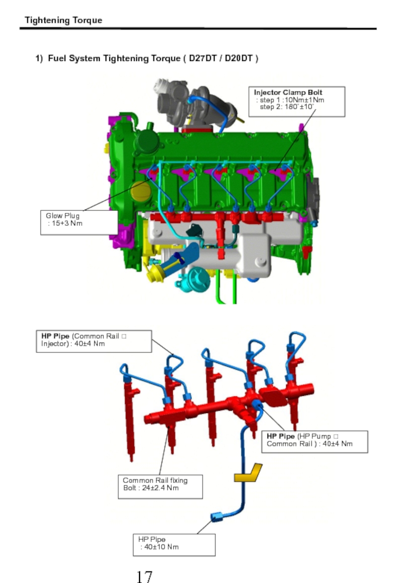
Слайд 18HP Pipe (Common Rail ? Injector) : 40±4 Nm
HP Pipe
:
Common Rail fixing Bolt : 24±2.4 Nm
1) Fuel System Tightening Torque ( D27DT / D20DT )
Injector Clamp Bolt
: step 1 :10Nm±1Nm
step 2: 180˚±10˚
Glow Plug
: 15+3 Nm
Tightening Torque
HP Pipe (HP Pump ? Common Rail ) : 40±4 Nm
Слайд 19Tightening Torque
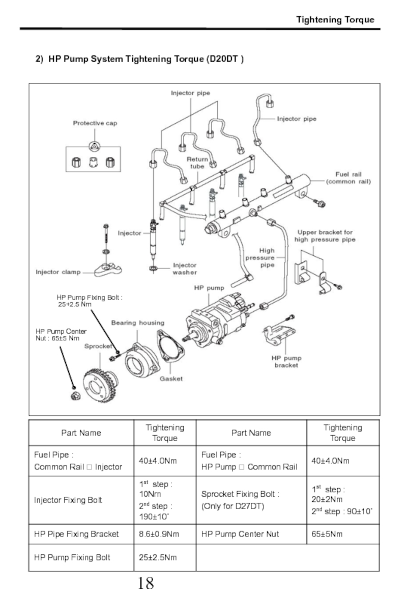
2) HP Pump System Tightening Torque (D20DT )
HP Pump Center
HP Pump Fixing Bolt :
25+2.5 Nm
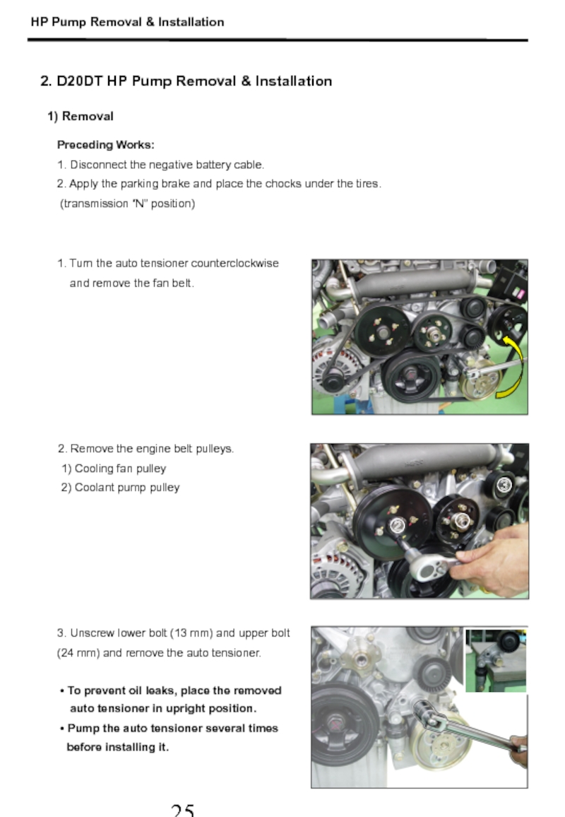
Слайд 261. Turn the auto tensioner counterclockwise
and remove the
2. Remove the engine belt pulleys.
1) Cooling fan pulley
2) Coolant pump pulley
Preceding Works:
1. Disconnect the negative battery cable.
2. Apply the parking brake and place the chocks under the tires.
(transmission “N” position)
3. Unscrew lower bolt (13 mm) and upper bolt
(24 mm) and remove the auto tensioner.
• To prevent oil leaks, place the removed
auto tensioner in upright position.
• Pump the auto tensioner several times
before installing it.
2. D20DT HP Pump Removal & Installation
1) Removal
①
③
②
HP Pump Removal & Installation
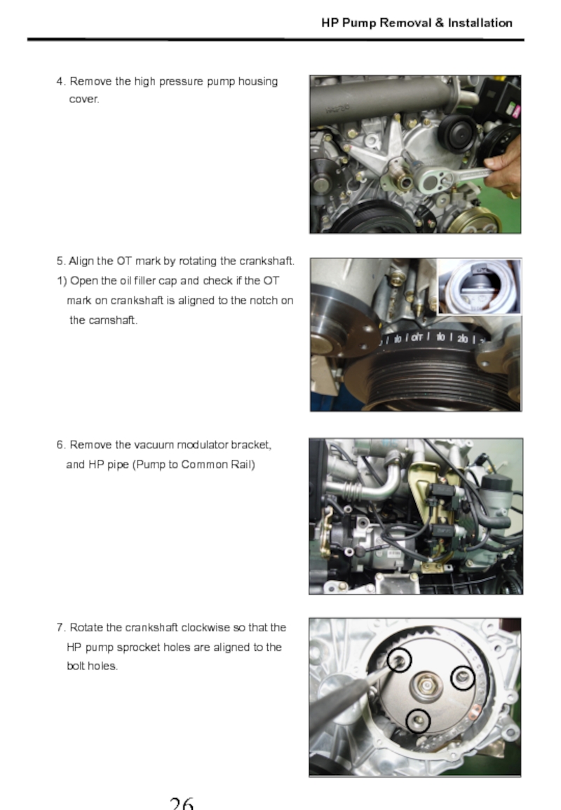
Слайд 275. Align the OT mark by rotating the crankshaft.
1) Open the
mark on crankshaft is aligned to the notch on
the camshaft.
6. Remove the vacuum modulator bracket,
and HP pipe (Pump to Common Rail)
4. Remove the high pressure pump housing
cover.
7. Rotate the crankshaft clockwise so that the
HP pump sprocket holes are aligned to the
bolt holes.
HP Pump Removal & Installation
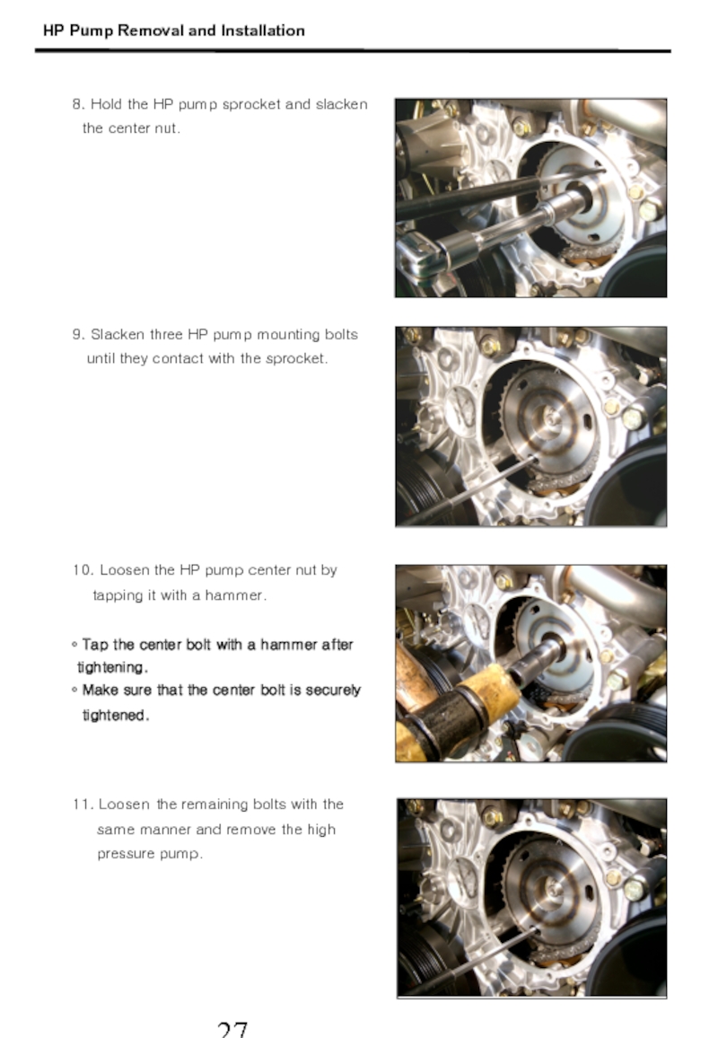
Слайд 289. Slacken three HP pump mounting bolts
until they
10. Loosen the HP pump center nut by
tapping it with a hammer.
• Tap the center bolt with a hammer after
tightening.
• Make sure that the center bolt is securely
tightened.
8. Hold the HP pump sprocket and slacken
the center nut.
11. Loosen the remaining bolts with the
same manner and remove the high
pressure pump.
HP Pump Removal and Installation
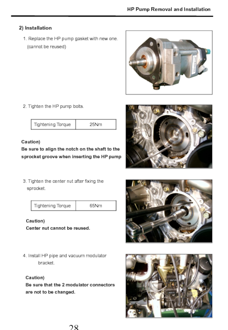
Слайд 292. Tighten the HP pump bolts.
3. Tighten the center nut after
sprocket.
1. Replace the HP pump gasket with new one.
(cannot be reused)
4. Install HP pipe and vacuum modulator bracket.
Caution)
Be sure that the 2 modulator connectors
are not to be changed.
2) Installation
Caution)
Center nut cannot be reused.
Caution)
Be sure to align the notch on the shaft to the
sprocket groove when inserting the HP pump
HP Pump Removal and Installation
Слайд 306. Install auto tensioner and belt pulley.
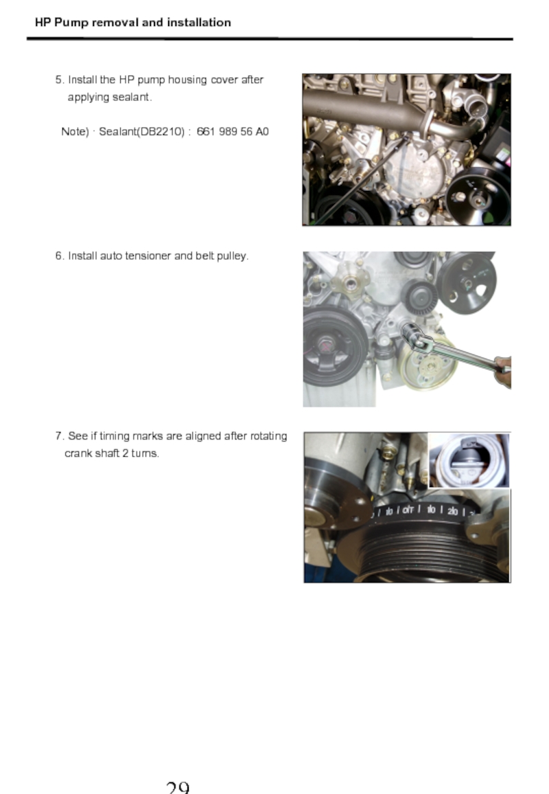
7. See if timing marks
crank shaft 2 turns.
5. Install the HP pump housing cover after
applying sealant.
Note) · Sealant(DB2210) : 661 989 56 A0
HP Pump removal and installation
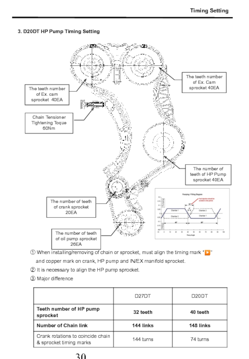
Слайд 31① When installing/removing of chain or sprocket, must align the timing
and copper mark on crank, HP pump and IN/EX manifold sprocket.
② It is necessary to align the HP pump sprocket.
③ Major difference
3. D20DT HP Pump Timing Setting
The teeth number of Ex. cam sprocket 40EA
The teeth number of Ex. Cam sprocket 40EA
Chain Tensioner Tightening Toque 60Nm
The number of teeth of HP Pump sprocket 40EA
The number of teeth of crank sprocket 20EA
The number of teeth of oil pump sprocket 26EA
Timing Setting
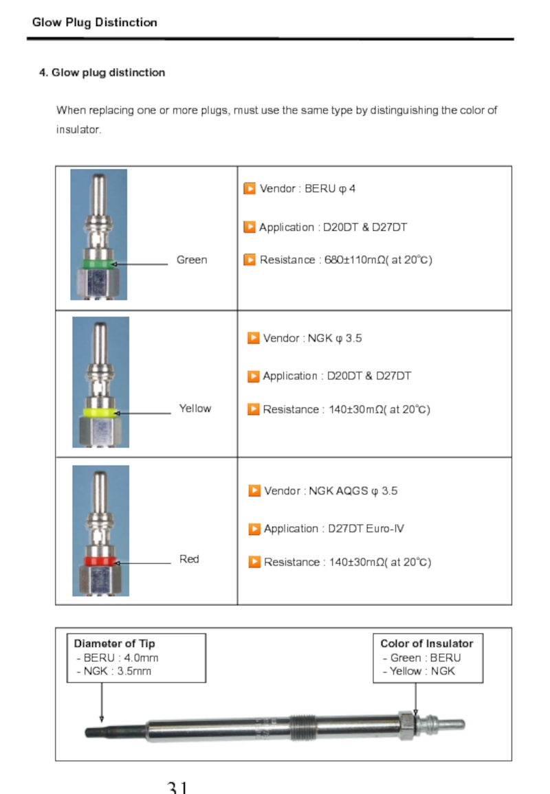
Слайд 324. Glow plug distinction
When replacing one or more plugs, must use
▶ Vendor : BERU φ 4
▶ Application : D20DT & D27DT
▶ Resistance : 680±110mΩ( at 20℃)
Green
Yellow
Red
Color of Insulator
- Green : BERU
- Yellow : NGK
Diameter of Tip
- BERU : 4.0mm
- NGK : 3.5mm
Glow Plug Distinction
▶ Vendor : NGK φ 3.5
▶ Application : D20DT & D27DT
▶ Resistance : 140±30mΩ( at 20℃)
▶ Vendor : NGK AQGS φ 3.5
▶ Application : D27DT Euro-IV
▶ Resistance : 140±30mΩ( at 20℃)
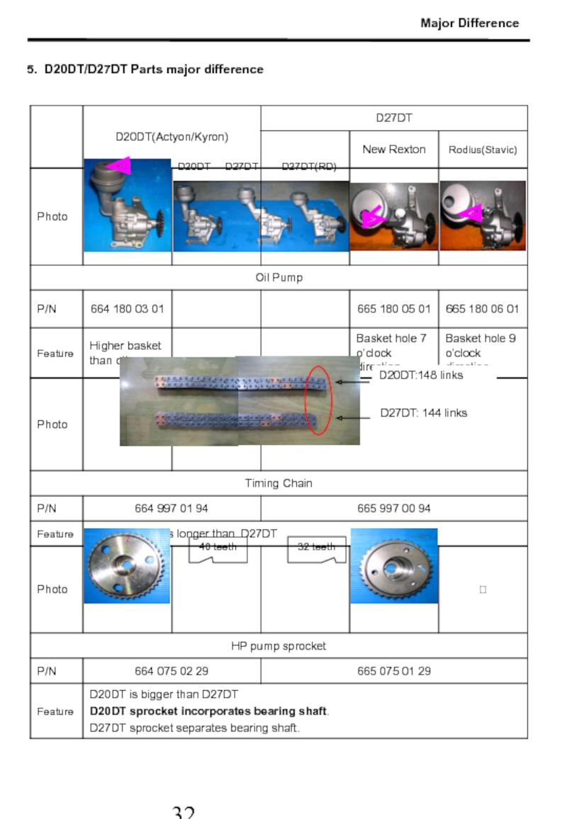
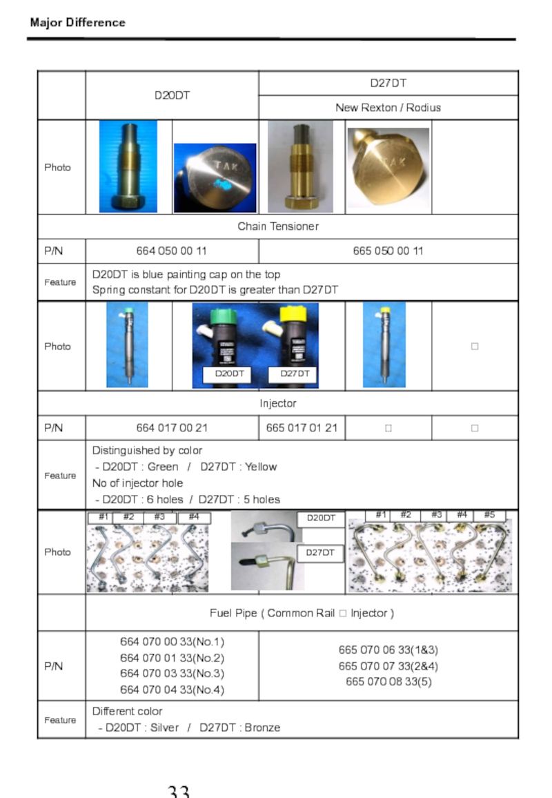
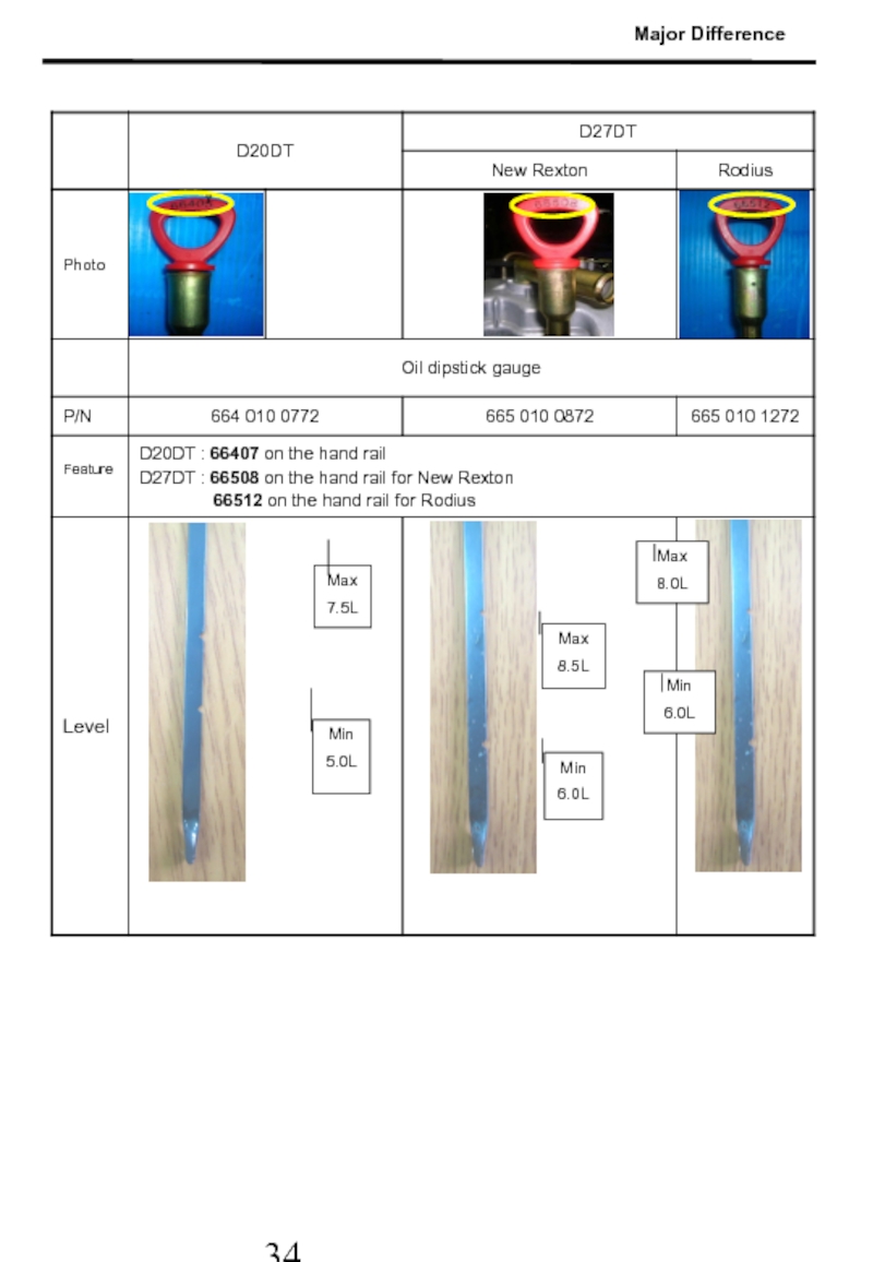
Слайд 33D20DT D27DT D27DT(RD)
5. D20DT/D27DT Parts major
D20DT:148 links
D27DT: 144 links
Major Difference
40 teeth
32 teeth
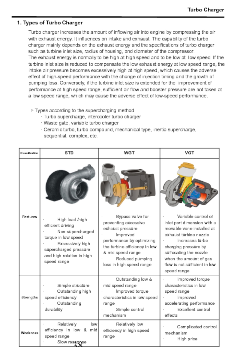
Слайд 39Turbo Charger
Turbo charger increases the amount of inflowing air into engine
The exhaust energy is normally to be high at high speed and to be low at low speed. If the turbine inlet size is reduced to compensate the low exhaust energy at low speed range, the intake air pressure becomes excessively high at high speed, which causes the adverse effect of high-speed performance with the change of injection timing and the growth of pumping loss. Conversely, if the turbine inlet size is extended for the improvement of performance at high speed range, sufficient air flow and booster pressure are not taken at a low speed range, which may cause the adverse effect of low-speed performance.
▷ Types according to the supercharging method
· Turbo supercharge, intercooler turbo charger
· Waste gate, variable turbo charger
· Ceramic turbo, turbo compound, mechanical type, inertia supercharge, sequential, complex, etc.
1. Types of Turbo Charger
Слайд 402. VGT Principle (Variable Geometry Turbocharger)
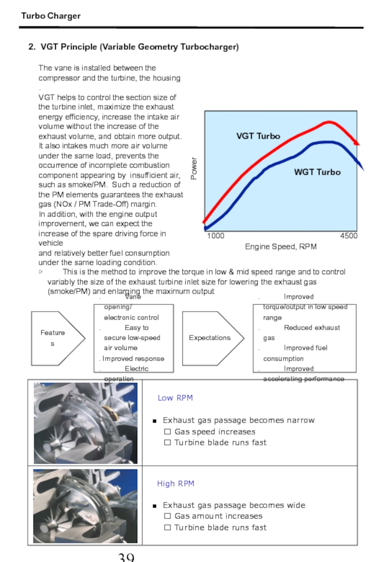
The vane is installed between the
VGT helps to control the section size of the turbine inlet, maximize the exhaust energy efficiency, increase the intake air volume without the increase of the exhaust volume, and obtain more output.
It also intakes much more air volume
under the same load, prevents the occurrence of incomplete combustion component appearing by insufficient air, such as smoke/PM. Such a reduction of the PM elements guarantees the exhaust gas (NOx / PM Trade-Off) margin.
In addition, with the engine output improvement, we can expect the increase of the spare driving force in vehicle
and relatively better fuel consumption under the same loading condition.
Engine Speed, RPM
1000
4500
VGT Turbo
WGT Turbo
Power
▷ This is the method to improve the torque in low & mid speed range and to control variably the size of the exhaust turbine inlet size for lowering the exhaust gas (smoke/PM) and enlarging the maximum output
Features
. Improved torque/output in low speed range
. Reduced exhaust gas
. Improved fuel consumption
. Improved accelerating performance
Expectations
. Vane opening/
electronic control
. Easy to secure low-speed air volume
. Improved response
. Electric operation
Turbo Charger
High RPM
■ Exhaust gas passage becomes narrow
? Gas speed increases
? Turbine blade runs fast
Low RPM
■ Exhaust gas passage becomes wide
? Gas amount increases
? Turbine blade runs fast
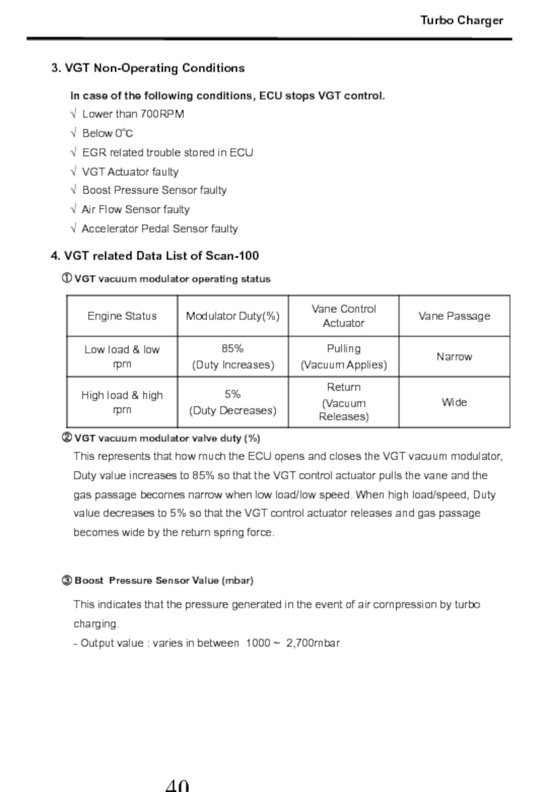
Слайд 41This represents that how much the ECU opens and closes the
3. VGT Non-Operating Conditions
4. VGT related Data List of Scan-100
① VGT vacuum modulator operating status
② VGT vacuum modulator valve duty (%)
This indicates that the pressure generated in the event of air compression by turbo charging.
- Output value : varies in between 1000 ~ 2,700mbar
③ Boost Pressure Sensor Value (mbar)
In case of the following conditions, ECU stops VGT control.
√ Lower than 700RPM
√ Below 0℃
√ EGR related trouble stored in ECU
√ VGT Actuator faulty
√ Boost Pressure Sensor faulty
√ Air Flow Sensor faulty
√ Accelerator Pedal Sensor faulty
Turbo Charger
Слайд 42[ VGT Actuator Duty Value (%) ]
[ Low rpm/low load ]
Check
At high rpm/high injection amount, the boost pressure value is also increased up to 2,700mbar its maximum pressure. If boost pressure sensor value is not as high as it’s requested, must check the boost pressure sensor or VGT system.
③ VGT control analysis
Turbo Charger
[ High load/Stall test ]
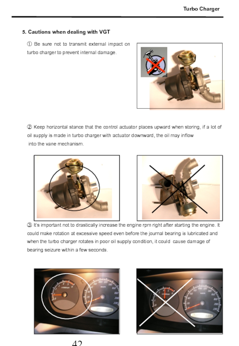
Слайд 43① Be sure not to transmit external impact on turbo charger
5. Cautions when dealing with VGT
② Keep horizontal stance that the control actuator places upward when storing, if a lot of oil supply is made in turbo charger with actuator downward, the oil may inflow
into the vane mechanism.
③ It’s important not to drastically increase the engine rpm right after starting the engine. It could make rotation at excessive speed even before the journal bearing is lubricated and when the turbo charger rotates in poor oil supply condition, it could cause damage of bearing seizure within a few seconds.
Turbo Charger
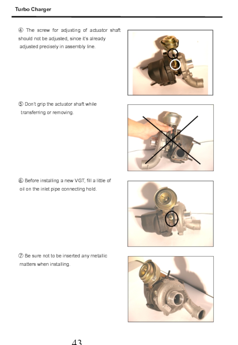
Слайд 44④ The screw for adjusting of actuator shaft should not be
adjusted precisely in assembly line.
⑤ Don’t grip the actuator shaft while
transferring or removing.
⑥ Before installing a new VGT, fill a little of
oil on the inlet pipe connecting hold.
⑦ Be sure not to be inserted any metallic
matters when installing.
Turbo Charger
Слайд 456. Turbo Charger Troubleshooting
Turbo charger trouble will hardly happen as long
Therefore, it is not necessary to check regularly upon mileage or running time, however,
it is strongly recommended to check according to the maintenance schedule.
The following symptoms may happen when it’s faulty.
· Deterioration of engine power.
· Engine noises
· Excessive engine oil consumption
· Excessive exhaust gas
The cause of these symptoms may result from engine itself and no trouble in turbo system. It is possible to foresee the trouble of turbo charger before removing it by checking the turbine.
① Check procedure
- Check if there is any problem in other engine systems.
- Check the condition of turbo charger
· whether turbine or pump blades are damaged by foreign matters.
· whether turbine or pump blades runs smoothly.
· whether lubricating system and cooling system are in good condition.
② Causes of turbo charger damage
- Problem of lubricant
· Insufficient lubricant
· Deteriorated lubricant
· Oil become sludge in center housing
- Inflow of foreign matters
· to compressor from air cleaner
· to turbine blade from exhaust manifold
- Excessively high temperature of exhaust gas
- Material or workers fault
Turbo Charger
Слайд 692. Scan-100 Data List : Actyon(D20) / New Rexton(D27)
At above 82 ℃ of ECT
Data List Analysis







![[ VGT Actuator Duty Value (%) ][ Low rpm/low load ]Check if the VGT operates](/img/tmb/5/474997/ecde8f18ca1dc3c8f9976dda37d2936d-800x.jpg)
