- Главная
- Разное
- Дизайн
- Бизнес и предпринимательство
- Аналитика
- Образование
- Развлечения
- Красота и здоровье
- Финансы
- Государство
- Путешествия
- Спорт
- Недвижимость
- Армия
- Графика
- Культурология
- Еда и кулинария
- Лингвистика
- Английский язык
- Астрономия
- Алгебра
- Биология
- География
- Детские презентации
- Информатика
- История
- Литература
- Маркетинг
- Математика
- Медицина
- Менеджмент
- Музыка
- МХК
- Немецкий язык
- ОБЖ
- Обществознание
- Окружающий мир
- Педагогика
- Русский язык
- Технология
- Физика
- Философия
- Химия
- Шаблоны, картинки для презентаций
- Экология
- Экономика
- Юриспруденция
WORKSHOP 8 SPRINGBACK ANALYSIS OF A JET ENGINE COWLING презентация
Содержание
- 1. WORKSHOP 8 SPRINGBACK ANALYSIS OF A JET ENGINE COWLING
- 3. Problem Description The focus of this workshop
- 4. Suggested Exercise Steps: Create a new database.
- 5. b c Create a new database. File
- 6. Step 2. Create Geometry and
- 7. Display the labels for the nodes. Step
- 8. d c b a File /
- 9. Tools / Laminate Modeler / Layup/Laminate.
- 10. Create / LM_Material / Add. Select
- 11. Step 6. Create Plies Using MSC.Laminate Modeler
- 12. Laminate Modeler: Create / LM_Ply /
- 13. Ply 1 Ply 2 Ply 3 Ply
- 14. Create the layup. Stack plies 1 through
- 15. Step 8. Check Plies Using MSC.Laminate Modeler
- 16. Laminate Modeler: Show / LM_Layup / Exploded
- 17. Step 10. Apply Uniform Temperature in MSC.Patran
- 18. Also, shown are the three nodes that
- 19. Step11. Create Nodal Displacement Constraints in MSC.Patran
- 20. Enter fixed_nodes_1 as the New Set
- 21. Analyze the problem and retrieve the results.
- 22. c b Select Default from Available
- 23. Click Apply. Access Results / Attach
- 24. Step 13. View the Deformation Results Postprocess
- 25. Step 14. Compensate the FE Model for
- 26. Offset / Nodes. Click Select Results.
- 27. Export a compensated FE model for the
- 28. a b c Create a new database.
- 29. Step 17. Import the Compensated FE Model
- 30. Step 17. Import the Compensated FE Model From IGES File
- 31. Create and analyze compensated FE model; optional
Слайд 1WORKSHOP 8
SPRINGBACK ANALYSIS OF A JET ENGINE COWLING
WS8-
PAT325, Workshop 8, February
Copyright© 2004 MSC.Software Corporation
Слайд 3Problem Description
The focus of this workshop is to show that the
Other things are required in this workshop, such as
Create plies
Create a layup
Visually determine if the plies and layup were correctly created
Run MSC.Nastran to determine the deformed shape of the model due to cooling to ambient temperature
Слайд 4Suggested Exercise Steps:
Create a new database.
Create geometry and mesh by reading
Create material properties by reading a session file
Create a new layup file
Create an MSC.Laminate Modeler material
Create plies using MSC.Laminate Modeler
Create MSC.Laminate Modeler layup
Check plies using MSC.Laminate Modeler
Check layup using MSC.Laminate Modeler
Apply uniform temperature in MSC.Patran
Create nodal displacement constraints in MSC.Patran
Run the analysis using MSC.Nastran
View the deformation results
Compensate the FE Model for the springback
Export the compensated FE model
Create a new MSC.Patran database
Import the compensated FE model from IGES file
Optional task
Слайд 5b
c
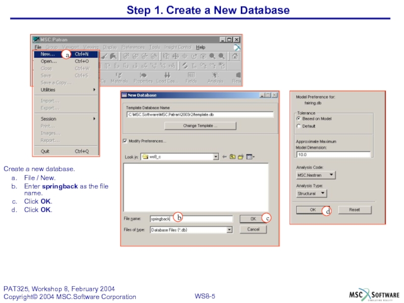
Create a new database.
File / New.
Enter springback as the file name.
Click
Click OK.
Step 1. Create a New Database
d
a
Слайд 6
Step 2. Create Geometry and Mesh by Reading a Session File
Play
File / Session.
Click Play.
Select springback_geom.ses as the File name.
Click -Apply-. (This action will cause the session file to be read. Please do not interrupt it.)
d
c
b
a
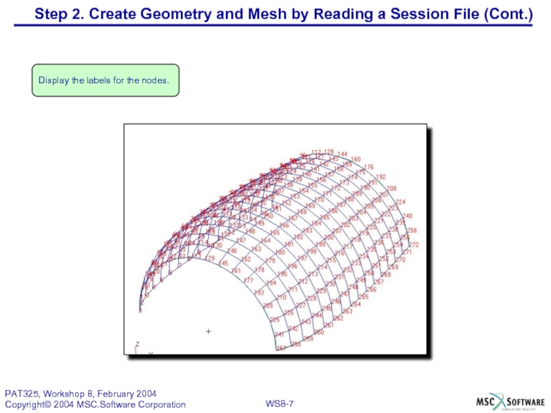
Слайд 7Display the labels for the nodes.
Step 2. Create Geometry and Mesh
Слайд 8d
c
b
a
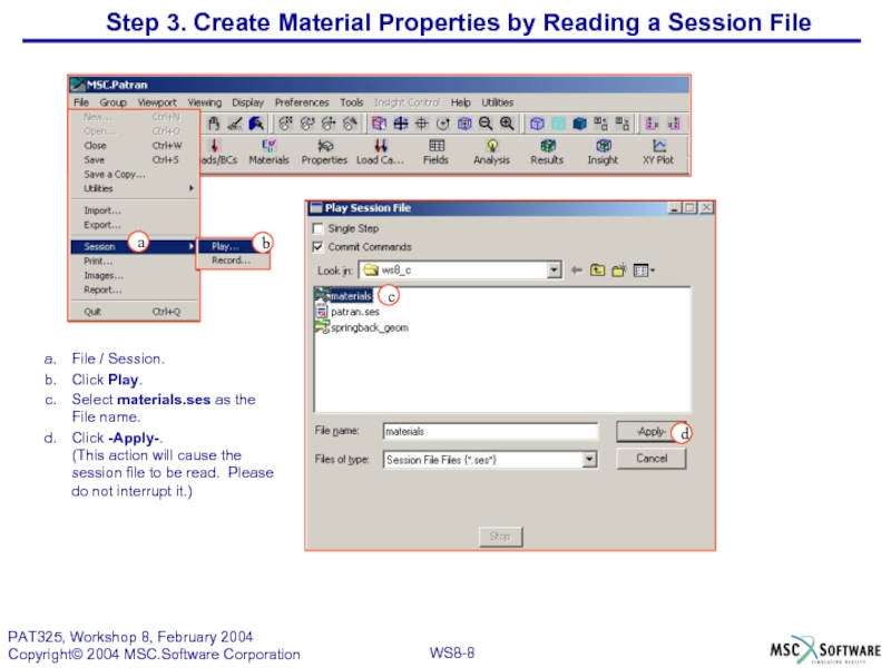
File / Session.
Click Play.
Select materials.ses as the File name.
Click -Apply-.
(This action
Step 3. Create Material Properties by Reading a Session File
Слайд 9
Tools / Laminate Modeler / Layup/Laminate.
Click New Layup File.
Enter springback as
Lick OK.
b
a
Step 4. Create a New Layup File
c
d
Слайд 10
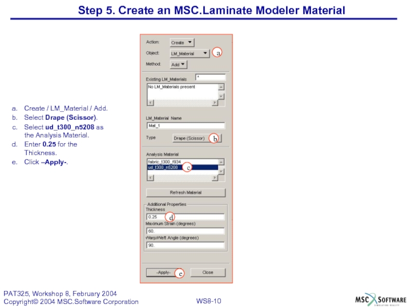
Create / LM_Material / Add.
Select Drape (Scissor).
Select ud_t300_n5208 as the Analysis
Enter 0.25 for the Thickness.
Click –Apply-.
a
e
c
d
Step 5. Create an MSC.Laminate Modeler Material
b
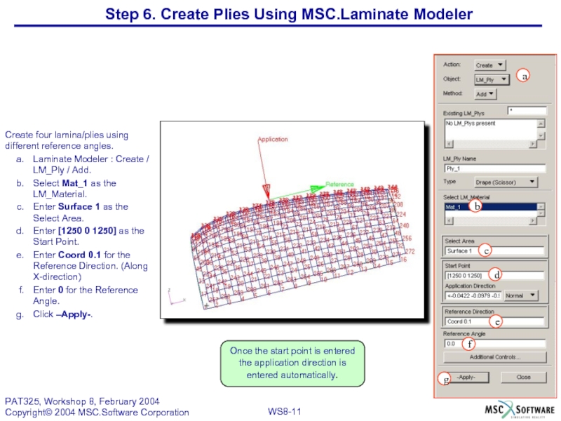
Слайд 11Step 6. Create Plies Using MSC.Laminate Modeler
f
b
c
d
g
a
e
Create four lamina/plies using different
Laminate Modeler : Create / LM_Ply / Add.
Select Mat_1 as the LM_Material.
Enter Surface 1 as the Select Area.
Enter [1250 0 1250] as the Start Point.
Enter Coord 0.1 for the Reference Direction. (Along X-direction)
Enter 0 for the Reference Angle.
Click –Apply-.
Once the start point is entered the application direction is entered automatically.
Слайд 12
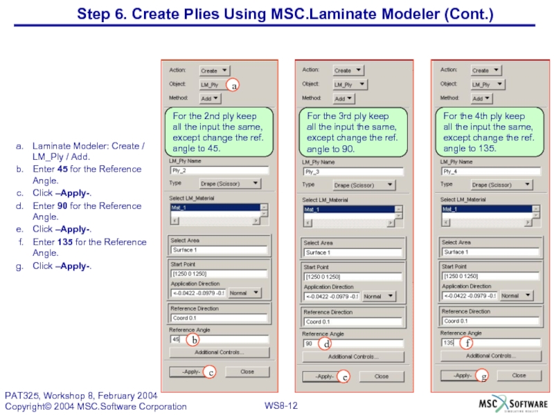
Laminate Modeler: Create / LM_Ply / Add.
Enter 45 for the Reference
Click –Apply-.
Enter 90 for the Reference Angle.
Click –Apply-.
Enter 135 for the Reference Angle.
Click –Apply-.
For the 3rd ply keep
all the input the same,
except change the ref.
angle to 90.
f
d
b
g
c
e
Step 6. Create Plies Using MSC.Laminate Modeler (Cont.)
For the 2nd ply keep
all the input the same,
except change the ref.
angle to 45.
For the 4th ply keep
all the input the same,
except change the ref.
angle to 135.
a
Слайд 14Create the layup. Stack plies 1 through 4, then repeat five
Laminate Modeler : Create / LM_Layup / Add.
Click Layup Definition.
Stack ply 1 through 4, in order. Do this six times, giving a 24 ply layup.
Click OK.
Click –Apply-.
Click OK to accept.
Step 7. Create MSC.Laminate Modeler Layup
b
c
a
Do not use any offsets. Use standard element type, and default tolerance.
e
d
Слайд 15Step 8. Check Plies Using MSC.Laminate Modeler
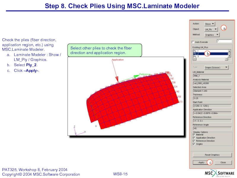
Check the plies (fiber direction,
Laminate Modeler : Show / LM_Ply / Graphics.
Select Ply_2.
Click –Apply-.
Select other plies to check the fiber direction and application region.
a
b
c
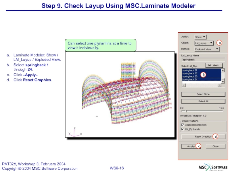
Слайд 16Laminate Modeler: Show / LM_Layup / Exploded View.
Select springback 1 through
Click –Apply-.
Click Reset Graphics.
b
c
d
a
Can select one ply/lamina at a time to view it individually.
Step 9. Check Layup Using MSC.Laminate Modeler
Слайд 17Step 10. Apply Uniform Temperature in MSC.Patran
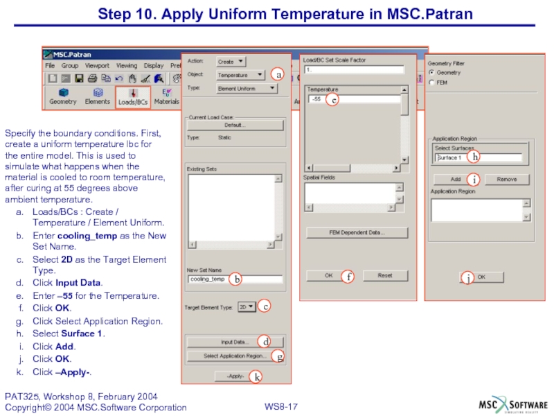
Specify the boundary conditions. First,
Loads/BCs : Create / Temperature / Element Uniform.
Enter cooling_temp as the New Set Name.
Select 2D as the Target Element Type.
Click Input Data.
Enter –55 for the Temperature.
Click OK.
Click Select Application Region.
Select Surface 1.
Click Add.
Click OK.
Click –Apply-.
f
g
a
j
i
c
d
e
h
b
k
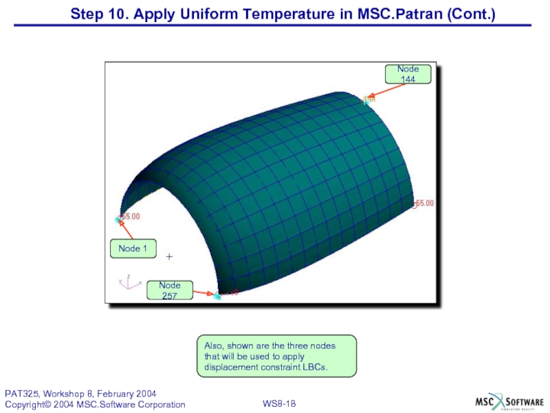
Слайд 18Also, shown are the three nodes that will be used to
Step 10. Apply Uniform Temperature in MSC.Patran (Cont.)
Слайд 19Step11. Create Nodal Displacement Constraints in MSC.Patran
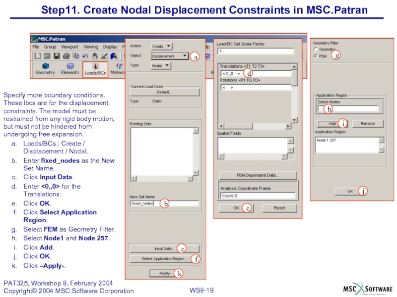
Specify more boundary conditions. These
Loads/BCs : Create / Displacement / Nodal.
Enter fixed_nodes as the New Set Name.
Click Input Data.
Enter <0,,0> for the Translations.
Click OK.
Click Select Application Region.
Select FEM as Geometry Filter.
Select Node1 and Node 257.
Click Add.
Click OK.
Click –Apply-.
a
k
i
b
e
j
c
d
f
h
g
Слайд 20
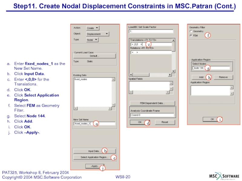
Enter fixed_nodes_1 as the New Set Name.
Click Input Data.
Enter for
Click OK.
Click Select Application Region.
Select FEM as Geometry Filter.
Select Node 144.
Click Add.
Click OK.
Click –Apply-.
j
h
a
d
i
b
c
e
g
f
Step11. Create Nodal Displacement Constraints in MSC.Patran (Cont.)
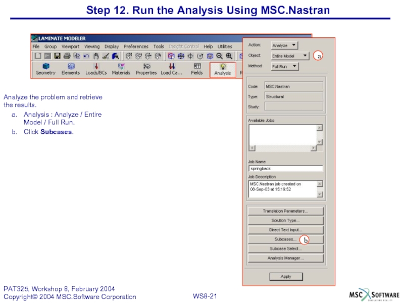
Слайд 21Analyze the problem and retrieve the results.
Analysis : Analyze / Entire
Click Subcases.
Step 12. Run the Analysis Using MSC.Nastran
a
b
Слайд 22c
b
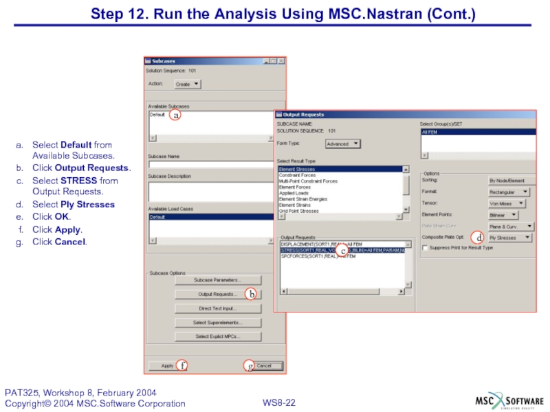
Select Default from Available Subcases.
Click Output Requests.
Select STRESS from Output Requests.
Select
Click OK.
Click Apply.
Click Cancel.
d
f
a
g
Step 12. Run the Analysis Using MSC.Nastran (Cont.)
Слайд 23
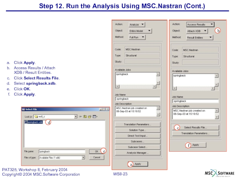
Click Apply.
Access Results / Attach XDB / Result Entities.
Click Select Results
Select springback.xdb.
Click OK.
Click Apply.
a
b
c
d
e
f
Step 12. Run the Analysis Using MSC.Nastran (Cont.)
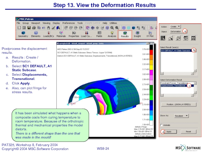
Слайд 24Step 13. View the Deformation Results
Postprocess the displacement results.
Results : Create
Select SC1 DEFAULT, A1 Static Subcase.
Select Displacements, Transnational.
Click Apply.
Also, can plot fringe for stress results.
a
d
c
It has been simulated what happens when a composite cools from curing temperature to room temperature. Because of the orthotropic thermal and mechanical properties the model distorts.
There is a different shape than the one that was made in the mould!
b
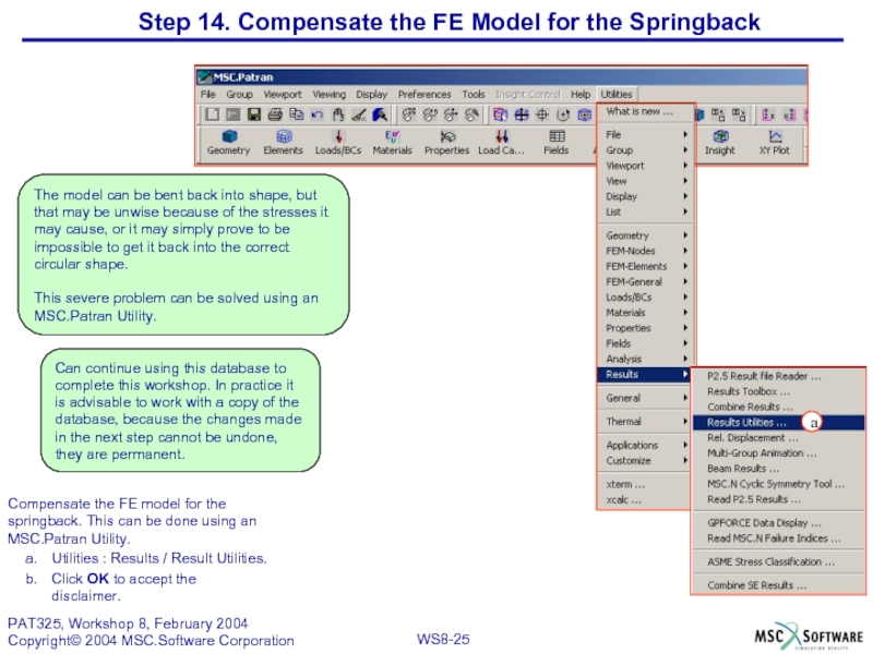
Слайд 25Step 14. Compensate the FE Model for the Springback
Compensate the FE
Utilities : Results / Result Utilities.
Click OK to accept the disclaimer.
a
The model can be bent back into shape, but that may be unwise because of the stresses it may cause, or it may simply prove to be impossible to get it back into the correct circular shape.
This severe problem can be solved using an MSC.Patran Utility.
Can continue using this database to complete this workshop. In practice it is advisable to work with a copy of the database, because the changes made in the next step cannot be undone, they are permanent.
Слайд 26
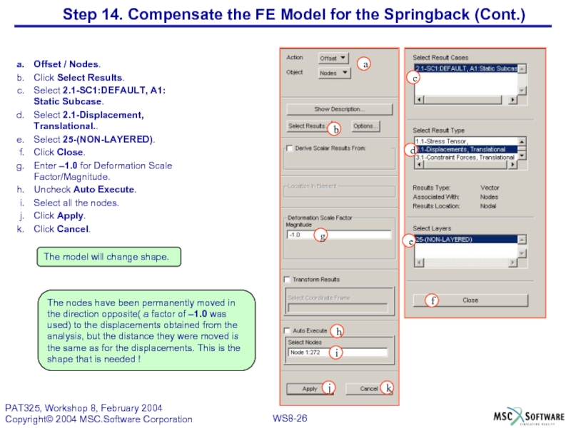
Offset / Nodes.
Click Select Results.
Select 2.1-SC1:DEFAULT, A1: Static Subcase.
Select 2.1-Displacement, Translational..
Select
Click Close.
Enter –1.0 for Deformation Scale Factor/Magnitude.
Uncheck Auto Execute.
Select all the nodes.
Click Apply.
Click Cancel.
g
c
d
a
i
e
h
j
b
k
The nodes have been permanently moved in the direction opposite( a factor of –1.0 was used) to the displacements obtained from the analysis, but the distance they were moved is the same as for the displacements. This is the shape that is needed !
f
Step 14. Compensate the FE Model for the Springback (Cont.)
The model will change shape.
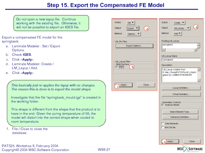
Слайд 27Export a compensated FE model for the springback.
Laminate Modeler : Set
Check IGES.
Click –Apply-.
Laminate Modeler: Create / LM_Layup / Add.
Click –Apply-.
File / Close to close the database.
d
b
c
e
a
This basically just re-applies the layup with no changes. The reason this is done is to export the mould shape.
Investigate that the file “springback_mould.igs” is created in the working folder.
This shape is different from the shape that the product is to have in the end. Given the curing temperature of 55, the model will distort into the correct shape when cooled to room temperature.
Do not open a new layup file. Continue working with the existing file. Otherwise, it will not be possible to export an IGES file.
Step 15. Export the Compensated FE Model
Слайд 28a
b
c
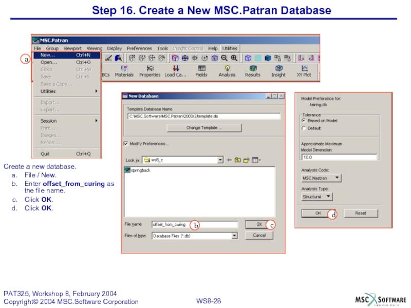
Create a new database.
File / New.
Enter offset_from_curing as the file name.
Click
Click OK.
d
Step 16. Create a New MSC.Patran Database
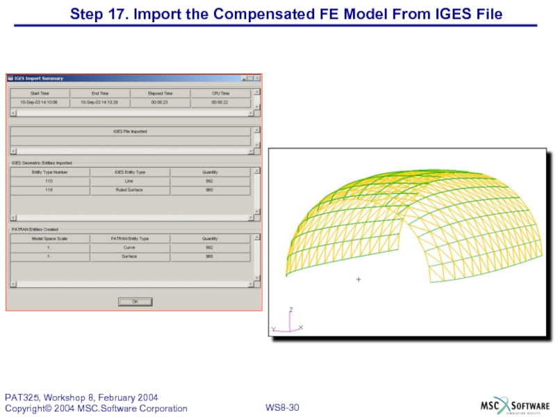
Слайд 29Step 17. Import the Compensated FE Model From IGES File
Import the
File / Import.
Select IGES as the Source.
Select springback_mould.igs.
Click –Apply-.
b
c
a
d
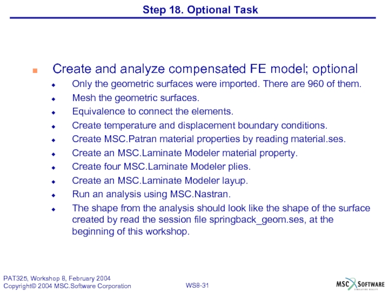
Слайд 31Create and analyze compensated FE model; optional
Only the geometric surfaces
Mesh the geometric surfaces.
Equivalence to connect the elements.
Create temperature and displacement boundary conditions.
Create MSC.Patran material properties by reading material.ses.
Create an MSC.Laminate Modeler material property.
Create four MSC.Laminate Modeler plies.
Create an MSC.Laminate Modeler layup.
Run an analysis using MSC.Nastran.
The shape from the analysis should look like the shape of the surface created by read the session file springback_geom.ses, at the beginning of this workshop.
Step 18. Optional Task

