- Главная
- Разное
- Дизайн
- Бизнес и предпринимательство
- Аналитика
- Образование
- Развлечения
- Красота и здоровье
- Финансы
- Государство
- Путешествия
- Спорт
- Недвижимость
- Армия
- Графика
- Культурология
- Еда и кулинария
- Лингвистика
- Английский язык
- Астрономия
- Алгебра
- Биология
- География
- Детские презентации
- Информатика
- История
- Литература
- Маркетинг
- Математика
- Медицина
- Менеджмент
- Музыка
- МХК
- Немецкий язык
- ОБЖ
- Обществознание
- Окружающий мир
- Педагогика
- Русский язык
- Технология
- Физика
- Философия
- Химия
- Шаблоны, картинки для презентаций
- Экология
- Экономика
- Юриспруденция
Basic Casing Design and Casing Point Selection презентация
Содержание
- 1. Basic Casing Design and Casing Point Selection
- 3. AJF Introduction Design Considerations
- 4. Statement of Standard
- 5. AJF Mechanical Properties Of Steel
- 6. Types of Casing
- 7. Types of Casing
- 8. Types of Casing
- 9. Types of Casing
- 10. Types of Casing
- 11. Types of Casing
- 12. AJF Casing Point Selection Why
- 13. Casing Point Selection Criteria
- 14. AJF Criteria For Selecting Casing Depths
- 15. AJF Other Restrictions On Casing Shoe
- 16. Casing Point Selection Criteria
- 17. AJF Special Criteria for Conductor The
- 18. AJF Special Criteria for Surface Casing
- 19. AJF Special Criteria for Intermediate Casing
- 20. AJF Intermediate Casing - other considerations
- 21. AJF Special Criteria for Production Casing
- 22. Casing Point Selection Criteria
- 23. Casing Point Selection Criteria
- 24. Casing Point Selection Criteria
- 25. Bottom
- 26. AJF Kick Tolerance
- 27. AJF Kick Tolerance More assumptions For
- 28. AJF Kick Tolerance Example: Casing shoe
- 29. AJF Kick Tolerance Example2: Casing shoe
- 30. Maximum
- 31. Maximum
- 32. Steps
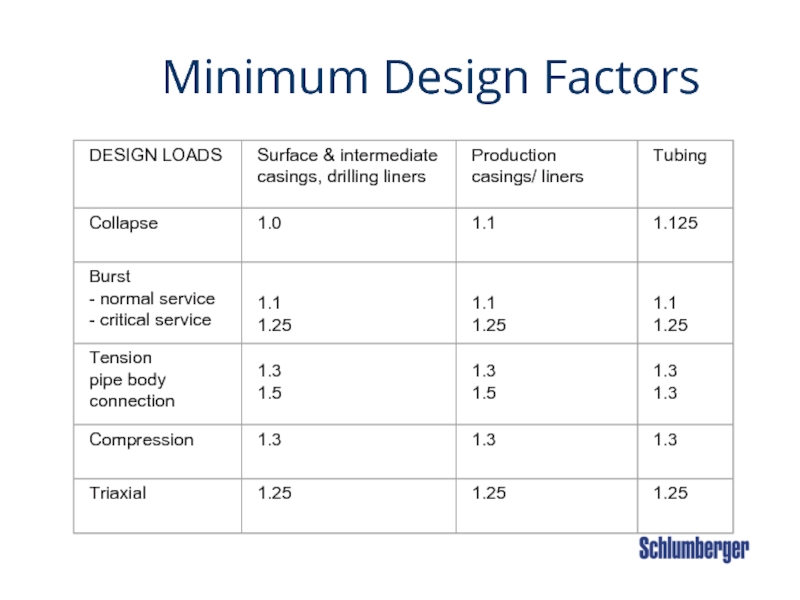
- 33. Minimum Design Factors
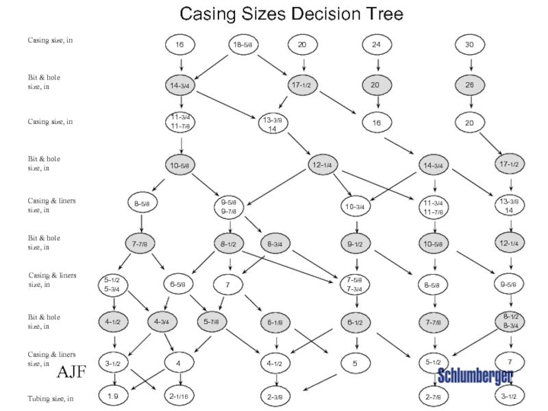
- 38. AJF Casing Sizes Decision Tree
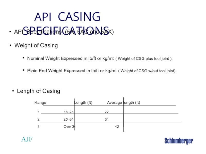
- 39. AJF API CASING SPECIFICATIONS
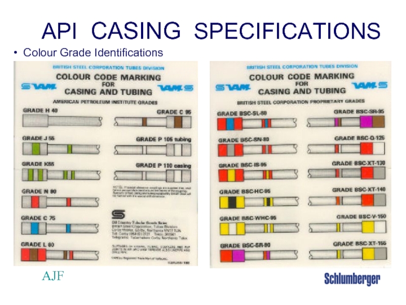
- 40. AJF API CASING SPECIFICATIONS Colour Grade Identifications
- 41. AJF
Слайд 2 Objectives
On completion
Define the different types of casings.
Describe the casing point selection process
Describe the maximum load casing design method.
Demonstrate the bottom up method of casing setting depth initial estimation.
Слайд 3 AJF
Introduction
Design Considerations
Cost, (usually up to 17% of the
Bottomhole Pressure,
Service Conditions (casing handling)
Material Properties
Internal Yield
Collapse
Tension
Слайд 4 Statement of Standard
All casing and tubing's shall
No well construction program shall be commenced without an approved casing and tubing design.
Слайд 5 AJF
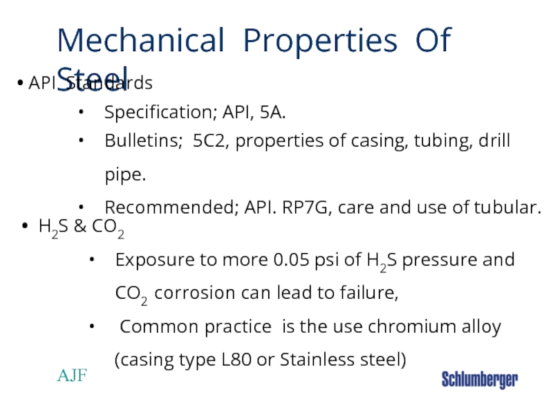
Mechanical Properties Of Steel
API Standards
Specification; API, 5A.
Bulletins; 5C2, properties of
Recommended; API. RP7G, care and use of tubular.
H2S & CO2
Exposure to more 0.05 psi of H2S pressure and CO2 corrosion can lead to failure,
Common practice is the use chromium alloy (casing type L80 or Stainless steel)
Слайд 7 Types of Casing Strings
Conductor Casing
Purpose
Provides mud returns
Divert flow in case of emergency.
Support subsequent casing loads.
Installation
Driven
Rathole set
Jetted
Drilled and cemented
Слайд 8 Types of Casing Strings
Surface Casing
Purpose
Protect Fresh
Provide wellbore integrity,
- Provides a BOP seal
- Allows drilling into abnormal pressure safely
Definition: Casing set at or above 6500’ or in sub-normal pressure.
Setting depth is based on mechanical and regulatory considerations
Слайд 9 Types of Casing Strings
Intermediate Casing
Purpose
Provide mechanical
- Case off problem zones.
- Provide higher fracture gradient as shoe for drilling operations and provide contingencies such as well control.
Definition: Casing set to 6500’ or deeper in abnormal pressure.
Setting depth is based on mechanical considerations
Слайд 10 Types of Casing Strings
Drilling Liners
Purpose
Provide mechanical
Definition: Partial string of casing hung in previously set casing string and is set to a depth greater than 6500’ or in abnormal pressure.
Setting Depth is based on mechanical considerations
Слайд 11 Types of Casing Strings
Production Casing/Liners
Purpose
Provide isolation
Withstand the anticipated loads during production and testing operations for the wells life time.
Setting Depth is the last string across the production zone. This may be a casing to surface or a liner that is hung.
Слайд 12 AJF
Casing Point Selection
Why Casing is Run in the Hole?
To consolidate the hole already drilled, (steel filter cake)
To provide the pressure control integrity to drill ahead.
Слайд 13 Casing Point Selection Criteria
Mechanical Considerations
Ability of the weakest exposed formation
Likelihood of differential sticking occurring while running casing.
Слайд 15 AJF
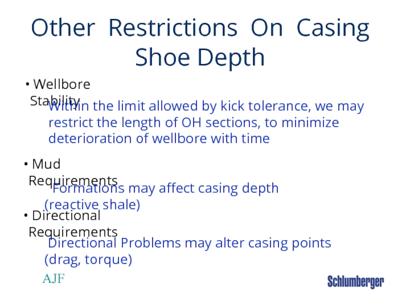
Other Restrictions On Casing Shoe Depth
Within the limit allowed by kick
Formations may affect casing depth (reactive shale)
Directional Problems may alter casing points (drag, torque)
Слайд 16 Casing Point Selection Criteria
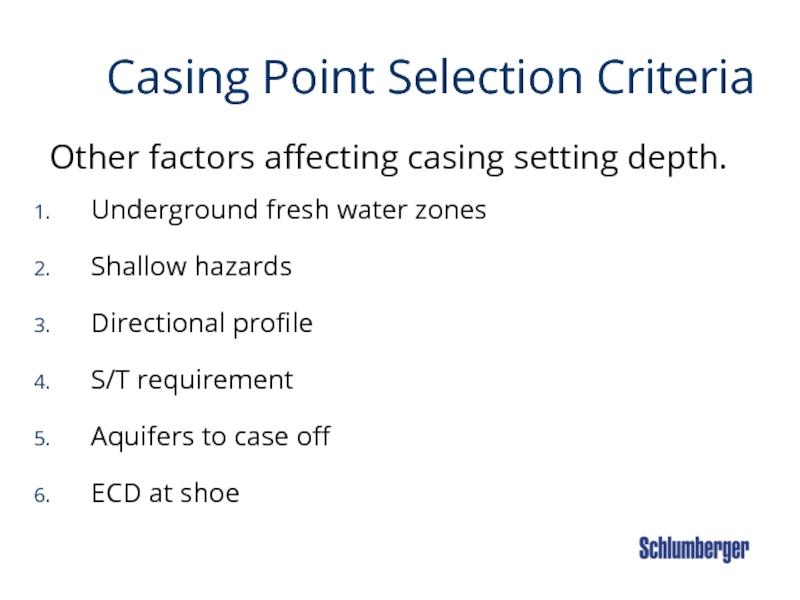
Other factors affecting casing setting depth.
Underground
Shallow hazards
Directional profile
S/T requirement
Aquifers to case off
ECD at shoe
Слайд 17 AJF
Special Criteria for Conductor
The Conductor pipe needs to be set deep
Слайд 18 AJF
Special Criteria for Surface Casing
The Surface Casing is usually set in
first competent formation which is strong
enough to close in on a kick.
Слайд 20 AJF
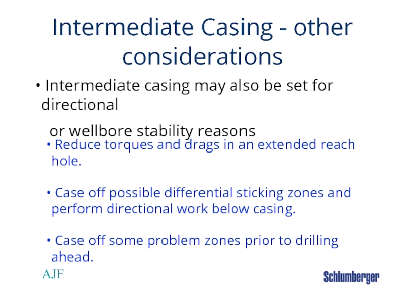
Intermediate Casing - other considerations
Reduce torques and drags in an
Case off possible differential sticking zones and perform directional work below casing.
Case off some problem zones prior to drilling ahead.
Intermediate casing may also be set for directional
or wellbore stability reasons
Слайд 21 AJF
Special Criteria for Production Casing
The Production Casing is set through or
just
type of completion to be used.
Слайд 22 Casing Point Selection Criteria
Information gathered prior to casing design.
Estimated pore
The minimum and maximum casing sizes to be run at TD that would allow for logging testing and a completion program.
The effects of geological uncertainties on casing setting depths and the ability to safely circulate out the maximum anticipated kick volume
Слайд 23 Casing Point Selection Criteria
After gathering Information
Develop a pore pressure and
Plan the well from TD up.
Determine the maximum formation pressure at TD.
Add a Trip margin and determine minimum weight at TD.
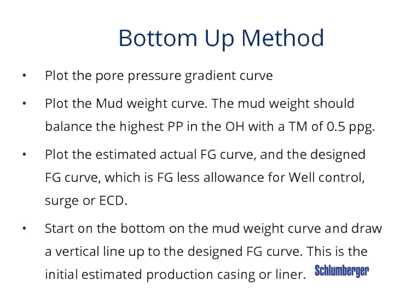
Слайд 25 Bottom Up Method
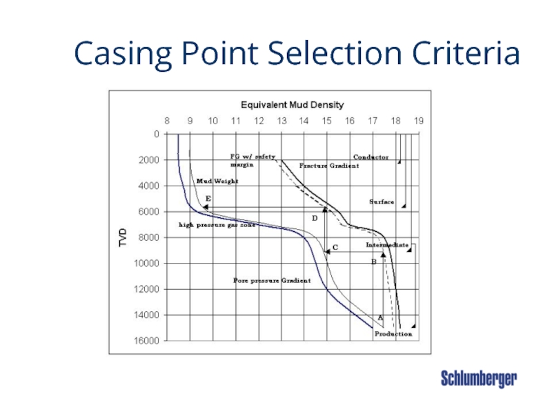
Plot the pore
Plot the Mud weight curve. The mud weight should balance the highest PP in the OH with a TM of 0.5 ppg.
Plot the estimated actual FG curve, and the designed FG curve, which is FG less allowance for Well control, surge or ECD.
Start on the bottom on the mud weight curve and draw a vertical line up to the designed FG curve. This is the initial estimated production casing or liner.
Cont…..
Слайд 26 AJF
Kick Tolerance
.
Kick tolerance is a measure of the size
The following assumption are made…
A gas influx from TD at the casing point or at TD.
The kicking formation has a pore pressure equal to or greater than the mud hydrostatic.
Shut in casing pressure = MAASP when the top of gas is at the casing shoe, using the drillers method.
Based on these assumptions, we calculate the volume of a gas kick. This is the maximum size of gas influx, which is what we call KICK TOLERANCE
Слайд 27 AJF
Kick Tolerance
More assumptions
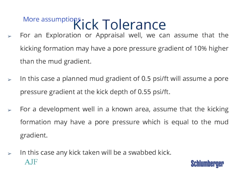
For an Exploration or Appraisal well, we can assume
In this case a planned mud gradient of 0.5 psi/ft will assume a pore pressure gradient at the kick depth of 0.55 psi/ft.
For a development well in a known area, assume that the kicking formation may have a pore pressure which is equal to the mud gradient.
In this case any kick taken will be a swabbed kick.
Слайд 28 AJF
Kick Tolerance
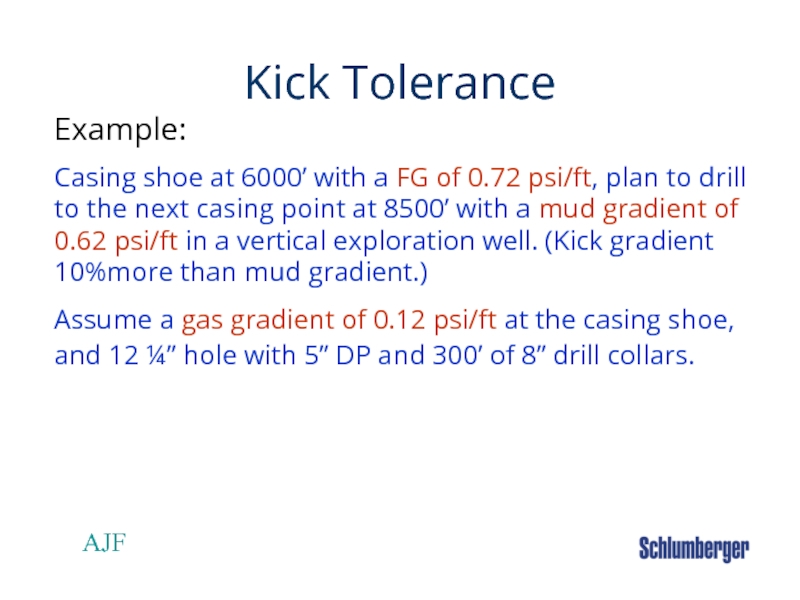
Example:
Casing shoe at 6000’ with a FG of 0.72 psi/ft,
Assume a gas gradient of 0.12 psi/ft at the casing shoe, and 12 ¼” hole with 5” DP and 300’ of 8” drill collars.
Слайд 29 AJF
Kick Tolerance
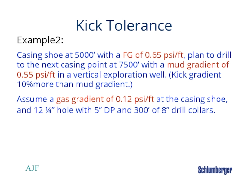
Example2:
Casing shoe at 5000’ with a FG of 0.65 psi/ft,
Assume a gas gradient of 0.12 psi/ft at the casing shoe, and 12 ¼” hole with 5” DP and 300’ of 8” drill collars.
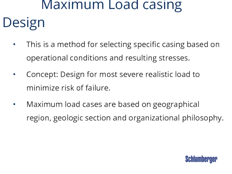
Слайд 30 Maximum Load casing Design
This is
Concept: Design for most severe realistic load to minimize risk of failure.
Maximum load cases are based on geographical region, geologic section and organizational philosophy.
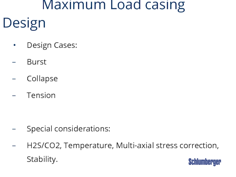
Слайд 31 Maximum Load casing Design
Design Cases:
Burst
Collapse
Tension
Special
H2S/CO2, Temperature, Multi-axial stress correction, Stability.
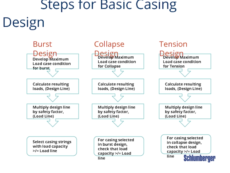
Слайд 32 Steps for Basic Casing Design
Develop
Calculate resulting loads, (Design Line)
Select casing strings with load capacity >/= Load line
Burst Design
Collapse Design
Develop Maximum Load case condition for Collapse
For casing selected in burst design, check that load capacity >/= Load line
Develop Maximum Load case condition for Tension
Tension Design
Calculate resulting loads, (Design Line)
Calculate resulting loads, (Design Line)
Multiply design line by safety factor, (Load Line)
Multiply design line by safety factor, (Load Line)
Multiply design line by safety factor, (Load Line)
For casing selected in collapse design, check that load capacity >/= Load line
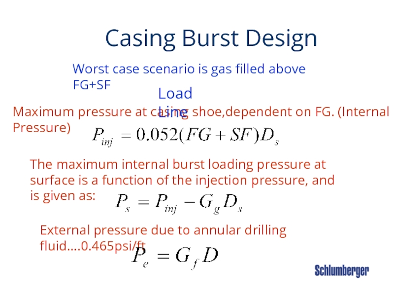
Слайд 34 Casing Burst
Maximum pressure at casing shoe,dependent on FG. (Internal Pressure)
The maximum internal burst loading pressure at surface is a function of the injection pressure, and is given as:
Load Line
External pressure due to annular drilling fluid….0.465psi/ft
Worst case scenario is gas filled above FG+SF
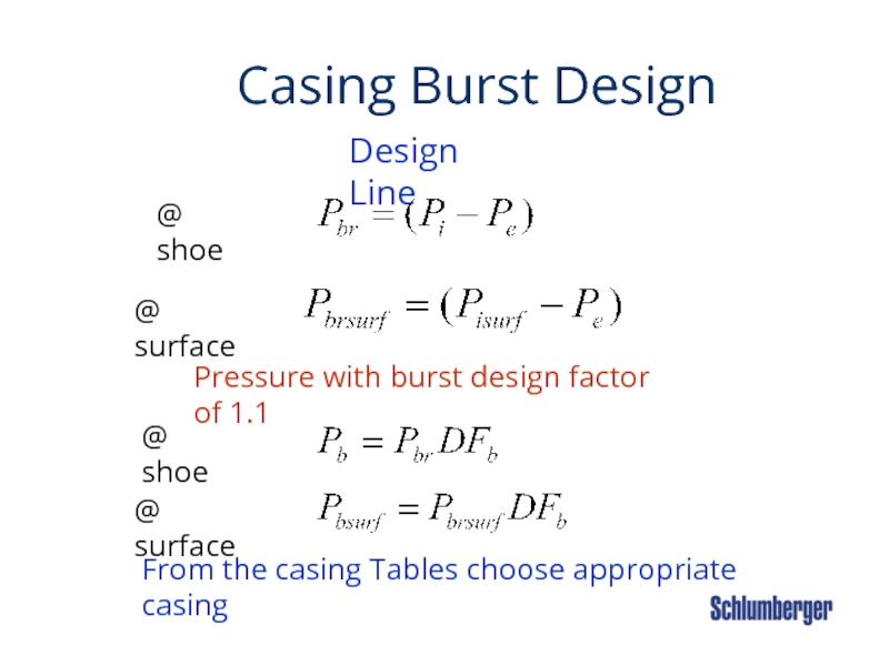
Слайд 35 Casing Burst
Pressure with burst design factor of 1.1
Design Line
@ shoe
@ surface
@ shoe
@ surface
From the casing Tables choose appropriate casing
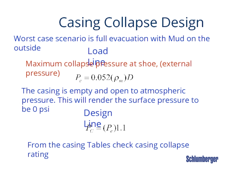
Слайд 36 Casing Collapse Design
Load
Worst case scenario is full evacuation with Mud on the outside
Maximum collapse pressure at shoe, (external pressure)
The casing is empty and open to atmospheric pressure. This will render the surface pressure to be 0 psi
Design Line
From the casing Tables check casing collapse rating
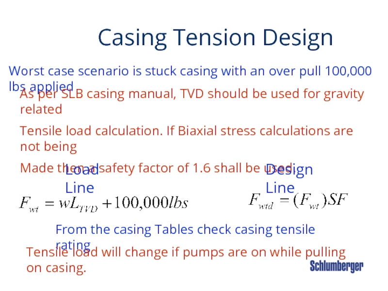
Слайд 37 Casing Tension Design
Worst
As per SLB casing manual, TVD should be used for gravity related
Tensile load calculation. If Biaxial stress calculations are not being
Made then a safety factor of 1.6 shall be used.
Load Line
Design Line
From the casing Tables check casing tensile rating
Tensile load will change if pumps are on while pulling on casing.
Слайд 38 AJF
Casing Sizes Decision Tree
Tubing size, in
Casing & liners
size, in
Bit & hole
size,
Casing size, in
Casing & liners
size, in
Bit & hole
size, in
Casing & liners
size, in
Bit & hole
size, in
Casing size, in
Bit & hole
size, in
16
14-3/4
11-3/4
11-7/8
10-5/8
8-5/8
7-7/8
5-1/2
5-3/4
4-1/2
3-1/2
1.9
20
17-1/2
13-3/8
14
12-1/4
8-3/4
6-1/8
4-1/2
2-3/8
10-3/4
9-1/2
7-5/8
7-3/4
6-1/2
5
24
20
16
14-3/4
11-3/4
11-7/8
10-5/8
8-5/8
7-7/8
5-1/2
2-7/8
30
26
20
17-1/2
13-3/8
14
12-1/4
9-5/8
8-1/2
8-3/4
7
3-1/2
18-5/8
9-5/8
9-7/8
8-1/2
7
5-7/8
6-5/8
4-3/4
4
2-1/16
Слайд 39 AJF
API CASING SPECIFICATIONS
API Specifications (5A, 5AC and 5AX)
Nominal Weight Expressed in lb/ft or kg/mt ( Weight of CSG plus tool joint ).
Plain End Weight Expressed in lb/ft or kg/mt ( Weight of CSG w/out tool joint) .
Length of Casing
Range Length (ft) Average length (ft)
1 16 -25 22
2 25 -34 31
3 Over 34 42
