- Главная
- Разное
- Дизайн
- Бизнес и предпринимательство
- Аналитика
- Образование
- Развлечения
- Красота и здоровье
- Финансы
- Государство
- Путешествия
- Спорт
- Недвижимость
- Армия
- Графика
- Культурология
- Еда и кулинария
- Лингвистика
- Английский язык
- Астрономия
- Алгебра
- Биология
- География
- Детские презентации
- Информатика
- История
- Литература
- Маркетинг
- Математика
- Медицина
- Менеджмент
- Музыка
- МХК
- Немецкий язык
- ОБЖ
- Обществознание
- Окружающий мир
- Педагогика
- Русский язык
- Технология
- Физика
- Философия
- Химия
- Шаблоны, картинки для презентаций
- Экология
- Экономика
- Юриспруденция
Site graphics. Graphical alarm management system презентация
Содержание
- 1. Site graphics. Graphical alarm management system
- 2. Cooper Site Graphics Graphical aid to manage
- 3. Cooper Site Graphics Secure System Multiple Users
- 4. System Application Large industrial or commercial sites
- 5. System Application Efficient facilities management Alarm
- 6. Hardware System Schematic
- 7. Hardware System Schematic Single PC to Cooper Fire network
- 8. Hardware System Schematic Multiple PC to
- 9. EC0232 Connections LON to RS232 converter Cooper
- 10. Requirements Coded Dongle Serial Number, Client ID,
- 11. Hardware Minimum PC Spec Intel Pentium
- 12. Operation Functionality Device Events Device text
- 13. Network Manager Parameters Baud Rate:
- 14. Network Network Manager Test Box Engineer /
- 15. Operation Getting Started PC Graphics 1024
- 16. Operation Graphics Format BMP preferred, GIF,
- 17. Setup of Input States Program Inputs Event
- 18. Symbols Simple Symbols 2 pictures for ON
- 19. Operator Access 2000 users max Unique pass-code
- 20. Operation Event Types Priority Handling Initial
- 21. Operation History Event Log Event History
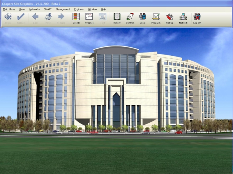
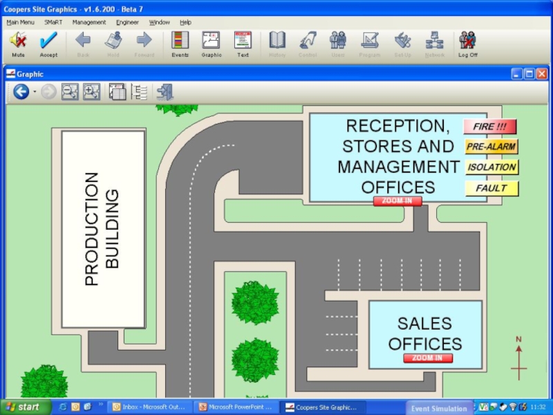
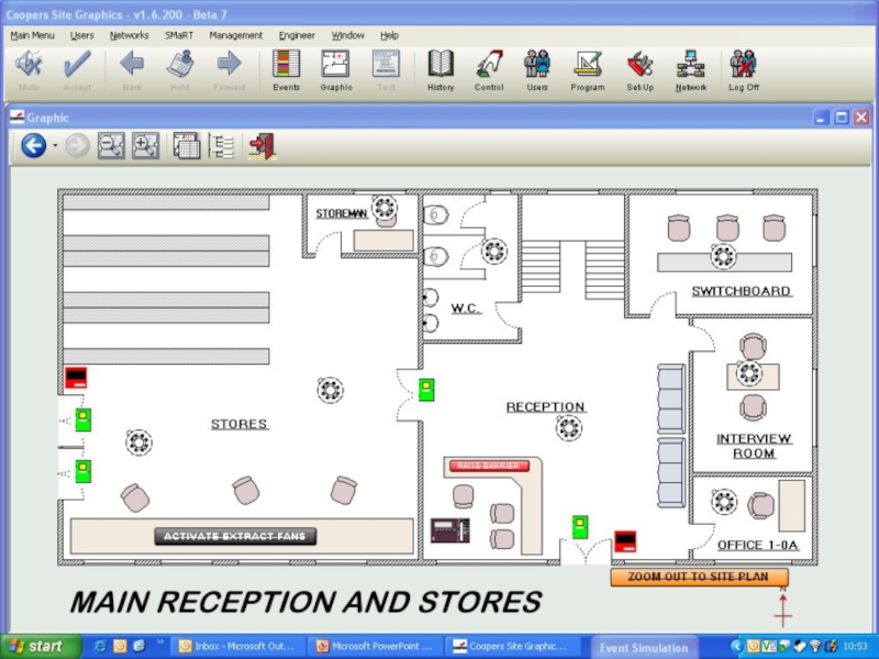
- 22. Examples Sample Screens Site Image Site
- 26. Operation Example Typical System
- 28. Start Communications Prepare Maps
- 29. Operation Fault Finding No Communication Check

Слайд 2Cooper Site Graphics
Graphical aid to manage alarm activations
Programmable to suit any
application
Hospitals, universities, hotels, etc
Simple, clear and user friendly
Efficient management of critical systems
Fire Alarm
Emergency Lighting
Allows Low-Skilled operation
PC based control
Improved record logging
Audit Trail
Multiple Users: 2000 max
Dongle protected
Hospitals, universities, hotels, etc
Simple, clear and user friendly
Efficient management of critical systems
Fire Alarm
Emergency Lighting
Allows Low-Skilled operation
PC based control
Improved record logging
Audit Trail
Multiple Users: 2000 max
Dongle protected
Introduction

Слайд 3Cooper Site Graphics
Secure System
Multiple Users and Multiple PC Workstations
Image, Plan or
Text Displays
Simple Navigation & Control
Current Event List and In-Depth Historical Analysis
Windows XP, 2000 Compatible
Choice of Specification
Simple Navigation & Control
Current Event List and In-Depth Historical Analysis
Windows XP, 2000 Compatible
Choice of Specification
Introduction

Слайд 4System Application
Large industrial or commercial sites
Critical safety requirements
Multiple building projects
Introduction


Слайд 9EC0232 Connections
LON to RS232 converter
Cooper Network to PC conversion hardware
Requires 230V
AC supply
Requires network connection
Requires PC RS232 serial connection
Requires network connection
Requires PC RS232 serial connection
Hardware

Слайд 10Requirements
Coded Dongle
Serial Number, Client ID, any additional options
Supplied with each software
package
Not required to install and run software
Will not communicate with Panels without dongle
Dongle plugs into the PC parallel port
USB dongle is available on request
Not required to install and run software
Will not communicate with Panels without dongle
Dongle plugs into the PC parallel port
USB dongle is available on request
Hardware

Слайд 11 Hardware
Minimum PC Spec
Intel Pentium 2GHz or equivalent
Windows 2000 SP4
Windows XP
Professional SP2
Memory
512Mb min memory
20Gb min disk space
Graphics
1024 x 768 XGA graphics card
16 million Colours
Connectivity
1 – 6 serial ports depending on configuration
Parallel or USB for Coded Dongle
10-100 Mps LAN connection for multiple work stations
Misc
Windows compatible sound card
2 button mouse and keyboard

Слайд 12 Operation
Functionality
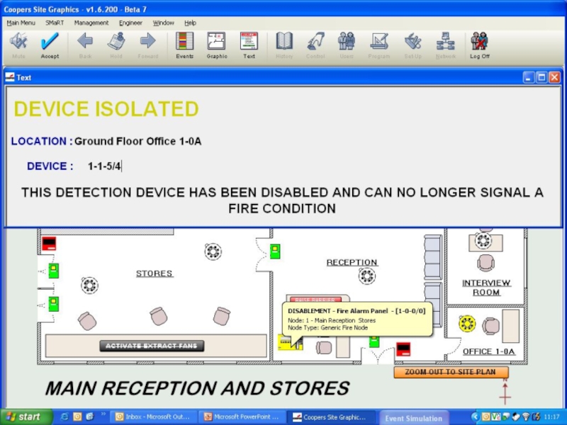
Device Events
Device text transmitted by control panel
Trigger device alarm or
fault to collect data
Data: 2-1-56/0 = Panel Address – Loop No. – Device Address / Input Type
Input types: 0 = Fire, 1 = Pre Alarm, 4 = Disablement, 6 = Fire Test, 8 = Fault
Panel Events
Global Reset, Silence, Evacuate
Power Fault, Battery Fault, Charger Fault
Sounder Fault, Earth Fault, FPE and FRE Faults
Disablement
Zone
Device

Слайд 13Network Manager
Parameters
Baud Rate: 4800
Parity:
None
Stop Bits: 1
Network Mon: 0
Comm Port: As required
Panel x - Offset: 0
Stop Bits: 1
Network Mon: 0
Comm Port: As required
Panel x - Offset: 0
Operation

Слайд 14Network
Network Manager Test Box
Engineer / Network Manager / Show Test Box
Count
increases if active
Recheck settings if not
Network Poll
Every 30 seconds
Generates Communications Error message
Recheck settings if not
Network Poll
Every 30 seconds
Generates Communications Error message
Operation

Слайд 15 Operation
Getting Started
PC Graphics
1024 x 768 Large Font
Display Properties / Settings
/ Advanced / DPI Settings / restart
WinXP: Display Properties (NOT Appearance / Font Size)
Logos and graphics may not display correctly with other font sizes
Administrator Login required
Install Site Graphics software
InsertDongle
Open Software, log-in (3112), configure Network Manager
WinXP: Display Properties (NOT Appearance / Font Size)
Logos and graphics may not display correctly with other font sizes
Administrator Login required
Install Site Graphics software
InsertDongle
Open Software, log-in (3112), configure Network Manager

Слайд 16 Operation
Graphics
Format
BMP preferred,
GIF, JPG, WMG also acceptable
1004 x 556 pixel
Preparation
Export from
AutoCAD
Screenshot conversion through photo packages
Import
Programming / Graphics Management / Import Picture File
Screenshot conversion through photo packages
Import
Programming / Graphics Management / Import Picture File

Слайд 17Setup of Input States
Program Inputs
Event types
Input alarm pages template
Reset Page template
Assign
graphics to inputs
Allocate symbols
Dialogue Box
Test Maps
Control Buttons
Zoom, Controls, etc
Allocate symbols
Dialogue Box
Test Maps
Control Buttons
Zoom, Controls, etc
Operation

Слайд 18Symbols
Simple Symbols
2 pictures for ON and OFF state of device
Compound Symbols
17
pictures for multiple states of device, ie Fault, Pre alarm, etc,
Operation


Слайд 20 Operation
Event Types
Priority
Handling
Initial Display of alarm
Text and Colour
Sounds
single or repeat
Mute on
ACCEPT
WAV format
WAV format

Слайд 21 Operation
History
Event Log
Event History
Control History
Isolation History
System History
Service History
User History
Search Tool
Print Facility


Слайд 28
Start Communications
Prepare Maps and import
Assign Graphics
Add Symbols
Use Dialogue Box to test
maps
Add Control Buttons for Zoom In/Out or Controls if required for multiple input states - e.g. detector fire, fault, disable, etc
Add Control Buttons for Zoom In/Out or Controls if required for multiple input states - e.g. detector fire, fault, disable, etc
Operation
Setup Steps

Слайд 29 Operation
Fault Finding
No Communication
Check Network Text Box for comms
Configure Network Manager
Insert
Dongle
Configure Panel for ‘Panel X of Y’
Event Graphics will not display in alarm
Check Event Priority
Functions Missing
Enter the relevant programming screen first
Log on with engineer code
Misc
Check graphics are 1004 x 556 pixels
Ensure your PC has Admin rights
Use the comprehensive Help files
Configure Panel for ‘Panel X of Y’
Event Graphics will not display in alarm
Check Event Priority
Functions Missing
Enter the relevant programming screen first
Log on with engineer code
Misc
Check graphics are 1004 x 556 pixels
Ensure your PC has Admin rights
Use the comprehensive Help files