- Главная
- Разное
- Дизайн
- Бизнес и предпринимательство
- Аналитика
- Образование
- Развлечения
- Красота и здоровье
- Финансы
- Государство
- Путешествия
- Спорт
- Недвижимость
- Армия
- Графика
- Культурология
- Еда и кулинария
- Лингвистика
- Английский язык
- Астрономия
- Алгебра
- Биология
- География
- Детские презентации
- Информатика
- История
- Литература
- Маркетинг
- Математика
- Медицина
- Менеджмент
- Музыка
- МХК
- Немецкий язык
- ОБЖ
- Обществознание
- Окружающий мир
- Педагогика
- Русский язык
- Технология
- Физика
- Философия
- Химия
- Шаблоны, картинки для презентаций
- Экология
- Экономика
- Юриспруденция
GUI composer. Embedded development tools презентация
Содержание
- 1. GUI composer. Embedded development tools
- 2. GUI Composer: See & Control Create GUI
- 3. When to use GUI Composer While debugging
- 4. GUIs are Comprised of Widgets GUI Composer
- 5. Example Application: InstaSpin GUI application for demonstrating
- 6. Customize how Widgets Look Most widgets can
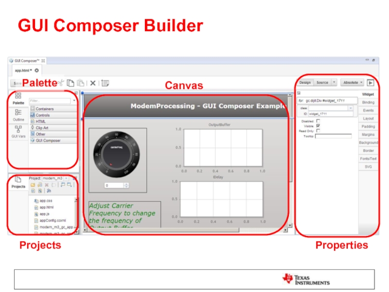
- 7. GUI Composer Builder Properties Projects Canvas Palette
- 8. Application Models Program Model CCS Debugger is
- 9. Program Model Symbol translation Symbols are translated
- 10. Streaming Model Data display Target application pushes
- 11. Adjusting Data Format It is possible to
- 12. Types of Applications CCS Plug-in Feature within
- 13. Configuration View Appears when the standalone app
- 14. GUI Composer Runtime GUI Composer applications need
- 15. Lab Requirements Software: Code Composer Studio v6.1.1.00022
- 16. Installation Instructions Download and install Code Composer
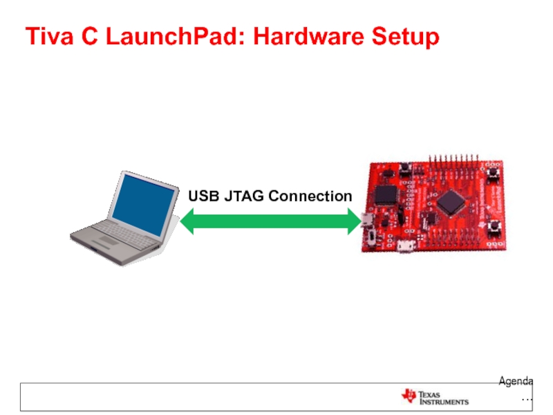
- 17. Tiva C LaunchPad: Hardware Setup Agenda … USB JTAG Connection
- 18. LAB 1: JTAG TRANSPORT LAB1A: CREATE
- 19. LAB conventions Lab steps are numbered
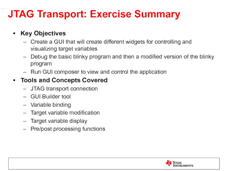
- 20. JTAG Transport: Exercise Summary Key Objectives Create
- 21. LAB1A: CREATE AND USE DIAL WIDGET
- 22. Launch CCS Double click on the Code
- 23. Import ‘blinky’ Project In the “Getting Started”
- 24. Modify the Code Expand the project in
- 25. Open GUI Composer Go to menu View
- 26. Create a New GUI Composer Project Click
- 27. Add a Dial Widget The Dial widget
- 28. Change the Appearance of the Dial Select
- 29. Bind a Variable to the Dial Make
- 30. Define Pre/Post Processing Functions Pre/Post Processing functions
- 31. Define Pre/Post Processing Functions Double-click on app.js
- 32. Generate App as a CCS Plug-in Click
- 33. Load Target Application If the Project Explorer
- 34. Preview the App Click on GUI Composer
- 35. Test the App using Preview Mode The
- 36. Test the App using Plug-in Go to
- 37. Clean Up Click the X on the
- 38. LAB1B: CREATE AND USE MORE WIDGETS
- 39. Modify the Code This step modifies the
- 40. Add the following code at the top
- 41. Add a Line Graph Widget The LineGraph
- 42. Set the Properties of the Line Graph
- 43. Bind Variables to the Line Graph Make
- 44. Add a Scatter Plot Widget The ScatterPlot
- 45. Set the Properties of the Scatter Plot
- 46. Bind Variables to the Scatter Plot Make
- 47. Add Label Widgets The Label widget is
- 48. Add Number Spinner Widgets The NumberSpinner widget
- 49. Set Properties and Bindings for Number Spinners
- 50. Set Properties and Bindings for Number Spinners
- 51. Add more Label Widgets In the GUI
- 52. Add TextBox Widgets The TextBox widget can
- 53. Set Bindings for TextBoxes Select the first
- 54. Set Bindings for TextBoxes Select the third
- 55. Set Bindings for TextBoxes In the converttoBinary
- 56. Add MultiImage Widget The MultiImage widget can
- 57. Add MultiImage Widget The steps below set
- 58. Set Binding for MultiImage Select the MultiImage
- 59. Set Binding for MultiImage In the ValueTooHigh
- 60. Add TextBox Widget This TextBox widget prints
- 61. Add GUI Vars GUI Vars allow you
- 62. Add GUI Vars For Server Bind Name,
- 63. Add GUI Vars In the onValue1PropertyChanged function
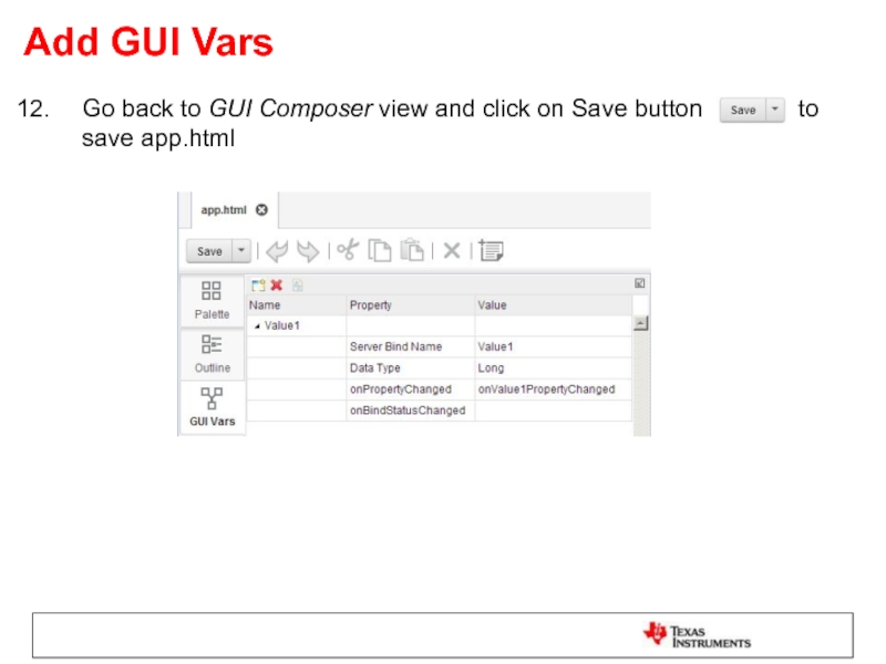
- 64. Add GUI Vars Go back to GUI
- 65. Load Target Application If the Project Explorer
- 66. Preview the App Click on GUI Composer
- 67. Test the App Click the Run button
- 68. Test the App Adjust the value of
- 69. Clean Up Click on the Exit Preview
- 70. Exporting the GUI Application Click on the
- 71. Add App to GUI Composer Runtime Open
- 72. Run the Standalone Application Close CCS Double
- 73. Run the Standalone Application When configuration is
- 74. LAB 2: UART TRANSPORT
- 75. LAB conventions Lab steps are numbered
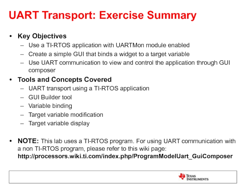
- 76. UART Transport: Exercise Summary Key Objectives Use
- 77. LAB 2: UART TRANSPORT EXAMPLE 20
- 78. Launch CCS Double click on the Code
- 79. Import and Build ‘GPIO Interrupt’ Project Go
- 80. Import and Build ‘GPIO Interrupt’ Project In
- 81. Review the RTOS configuration In Project Explorer
- 82. Add UART Communication to target config Find
- 83. Open GUI Composer Go to GUI Composer
- 84. Create a New GUI Composer Project If
- 85. Add a Dial Widget The Dial widget
- 86. Change the Appearance of the Dial Select
- 87. Bind a Variable to the Dial Make
- 88. Load Target Application If the Project Explorer
- 89. Load Symbols for UART Connection Once the
- 90. Preview the App Click on GUI Composer
- 91. Test the App Press the SW1 or
- 92. Clean Up Click on the Exit Preview
- 93. Exporting the GUI Application Click on the
- 94. Add App to GUI Composer Runtime Open
- 95. Run the Standalone Application Close CCS Power
- 96. Test the Standalone Application Press the SW1
- 97. Exercise Summary After completing the labs you
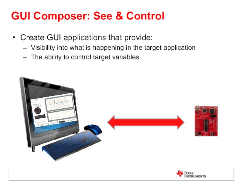
Слайд 2GUI Composer: See & Control
Create GUI applications that provide:
Visibility into what
The ability to control target variables
Слайд 3When to use GUI Composer
While debugging
Create simple displays that allow you
Standalone applications
Create GUI applications that allow you to see and control your application outside of the CCS environment
Great for demonstrations
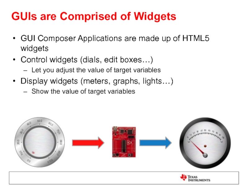
Слайд 4GUIs are Comprised of Widgets
GUI Composer Applications are made up of
Control widgets (dials, edit boxes…)
Let you adjust the value of target variables
Display widgets (meters, graphs, lights…)
Show the value of target variables
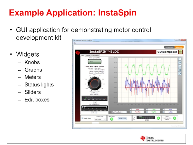
Слайд 5Example Application: InstaSpin
GUI application for demonstrating motor control development kit
Widgets
Knobs
Graphs
Meters
Status lights
Sliders
Edit
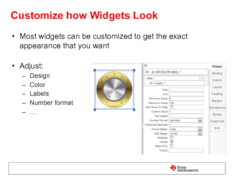
Слайд 6Customize how Widgets Look
Most widgets can be customized to get the
Adjust:
Design
Color
Labels
Number format
…
Слайд 8Application Models
Program Model
CCS Debugger is used to translate symbols to addresses
Writes
Data is requested by the GUI application
JTAG or Serial connections are used
Streaming Model
Data is streamed from the target application up to the host
Serial or Ethernet connections are used
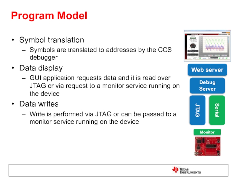
Слайд 9Program Model
Symbol translation
Symbols are translated to addresses by the CCS debugger
Data
GUI application requests data and it is read over JTAG or via request to a monitor service running on the device
Data writes
Write is performed via JTAG or can be passed to a monitor service running on the device
Web server
Debug Server
JTAG
Monitor
Serial
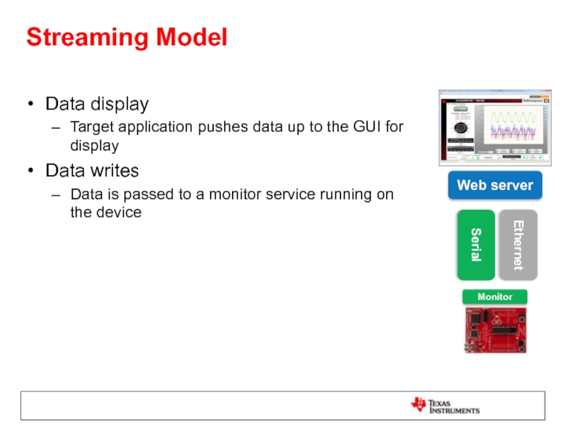
Слайд 10Streaming Model
Data display
Target application pushes data up to the GUI for
Data writes
Data is passed to a monitor service running on the device
Web server
Monitor
Serial
Ethernet
Слайд 11Adjusting Data Format
It is possible to adjust the value of data
Data may be stored in 1 unit of measure on the device but you wish to display it in the GUI in another
Pre-processing Function
Takes the value from the target and adjusts it for display
Post-processing Function
Takes the value entered in the widget and adjusts it prior to writing it to the device
Слайд 12Types of Applications
CCS Plug-in
Feature within CCS
Available from View menu within CCS
Standalone
Can be run without CCS
Requires the GUI Composer Runtime to be installed
http://processors.wiki.ti.com/index.php/GUI_Composer
Used for larger applications
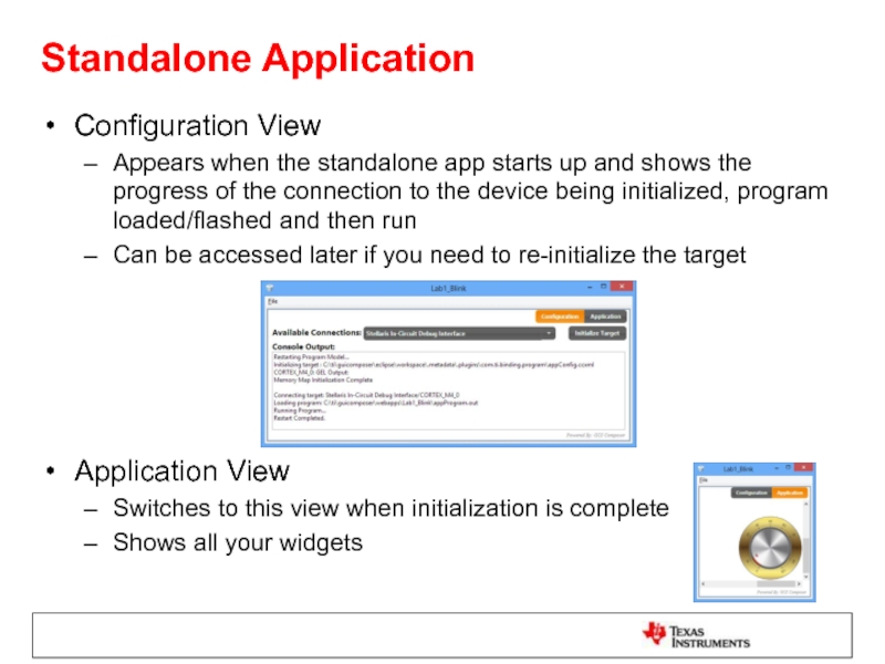
Слайд 13Configuration View
Appears when the standalone app starts up and shows the
Can be accessed later if you need to re-initialize the target
Application View
Switches to this view when initialization is complete
Shows all your widgets
Standalone Application
Слайд 14GUI Composer Runtime
GUI Composer applications need access to services (target read/write…)
These
Subset of CCS Functionality
Can be bundled with GUI Composer applications
Слайд 15Lab Requirements
Software:
Code Composer Studio v6.1.1.00022
GUI Composer (add-on in CCS)
TivaWare for
TI-RTOS for TivaC the 2.14.00.10 (only required for Lab2)
GUI Composer Runtime v6.1.1
Hardware:
Tiva C TM4C123GXL Launchpad
1 micro USB cable (included with LaunchPad kit)
Note: Labs should also run on TM4C1294XL Launchpad as long as appropriate example projects for that device are used
See Installation Instructions in next slide
Слайд 16Installation Instructions
Download and install Code Composer Studio v6.1.1.00022 from
http://processors.wiki.ti.com/index.php/Download_CCS
Start
In App Center:
Under Code Composer Studio Add-ons, select the following and install
GUI Composer
TI-RTOS for TivaC (only required for Lab2)
Under Code Composer Studio Standalone Software, select TivaWare, click on Download, then download and install to c:\ti
Download GUI Composer Runtime v6.1.1 from http://processors.wiki.ti.com/index.php/Category:GUI_Composer#GUI_Composer_Downloads and install to c:\ti
Слайд 19LAB conventions
Lab steps are numbered for easier reference
…
…
Explanations, notes, warnings are
Warnings are shown with
Information is marked with
Tips and answers are marked with
Questions are marked with
Слайд 20JTAG Transport: Exercise Summary
Key Objectives
Create a GUI that will create different
Debug the basic blinky program and then a modified version of the blinky program
Run GUI composer to view and control the application
Tools and Concepts Covered
JTAG transport connection
GUI Builder tool
Variable binding
Target variable modification
Target variable display
Pre/post processing functions
Слайд 22Launch CCS
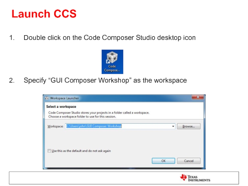
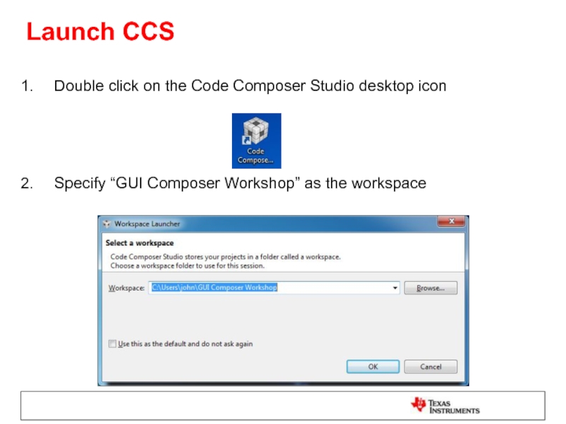
Double click on the Code Composer Studio desktop icon
Specify “GUI
Слайд 23Import ‘blinky’ Project
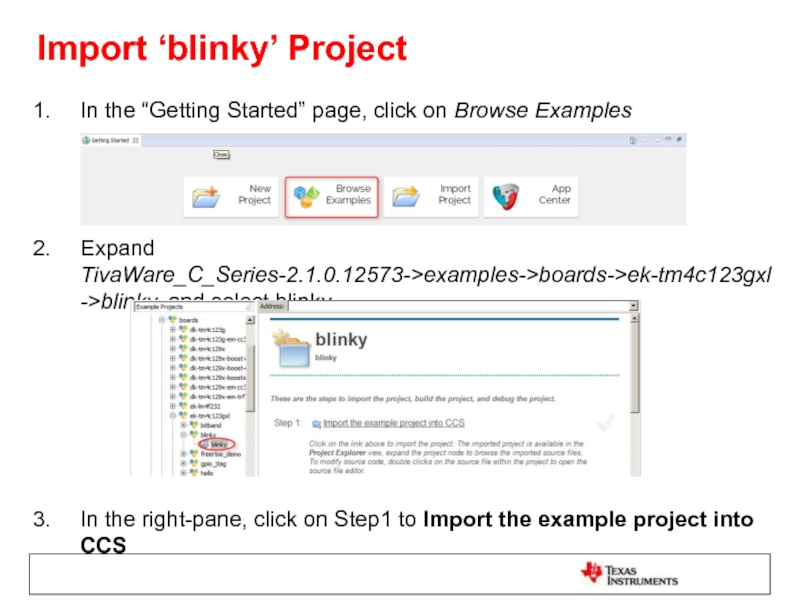
In the “Getting Started” page, click on Browse Examples
Expand
In the right-pane, click on Step1 to Import the example project into CCS
Слайд 24Modify the Code
Expand the project in the Project Explorer view to
Double-click on blinky.c to open it
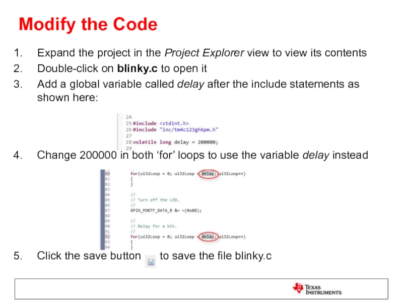
Add a global variable called delay after the include statements as shown here:
Change 200000 in both ‘for’ loops to use the variable delay instead
Click the save button to save the file blinky.c
Слайд 25Open GUI Composer
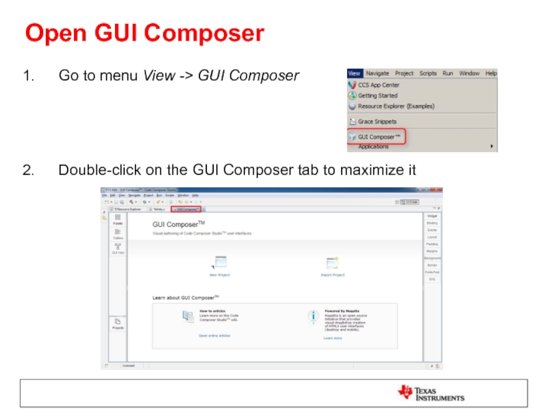
Go to menu View -> GUI Composer
Double-click on the
Слайд 26Create a New GUI Composer Project
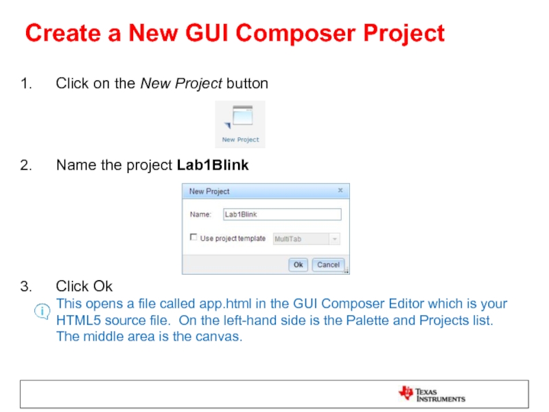
Click on the New Project button
Name
Click Ok This opens a file called app.html in the GUI Composer Editor which is your HTML5 source file. On the left-hand side is the Palette and Projects list. The middle area is the canvas.
Слайд 27Add a Dial Widget
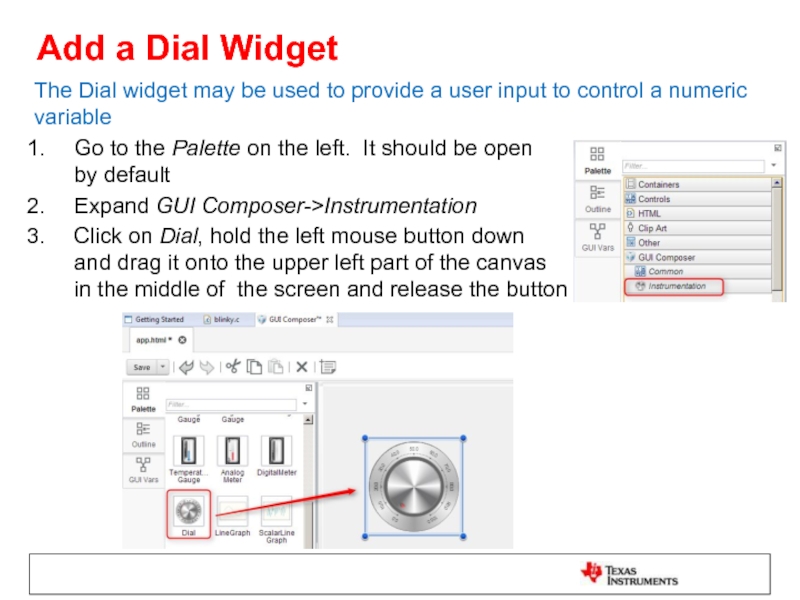
The Dial widget may be used to provide
Go to the Palette on the left. It should be open by default
Expand GUI Composer->Instrumentation
Click on Dial, hold the left mouse button down and drag it onto the upper left part of the canvas in the middle of the screen and release the button
Слайд 28Change the Appearance of the Dial
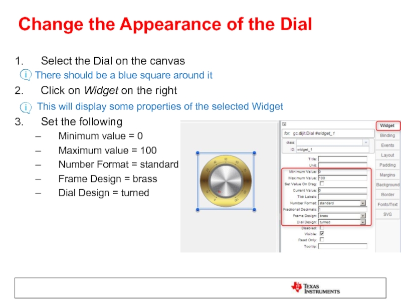
Select the Dial on the canvas
Click on Widget on the right
This will display some properties of the selected Widget
Set the following
Minimum value = 0
Maximum value = 100
Number Format = standard
Frame Design = brass
Dial Design = turned
Слайд 29Bind a Variable to the Dial
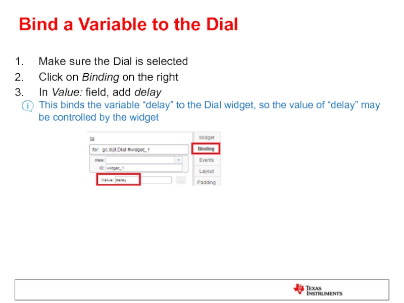
Make sure the Dial is selected
Click
In Value: field, add delay This binds the variable “delay” to the Dial widget, so the value of “delay” may be controlled by the widget
Слайд 30Define Pre/Post Processing Functions
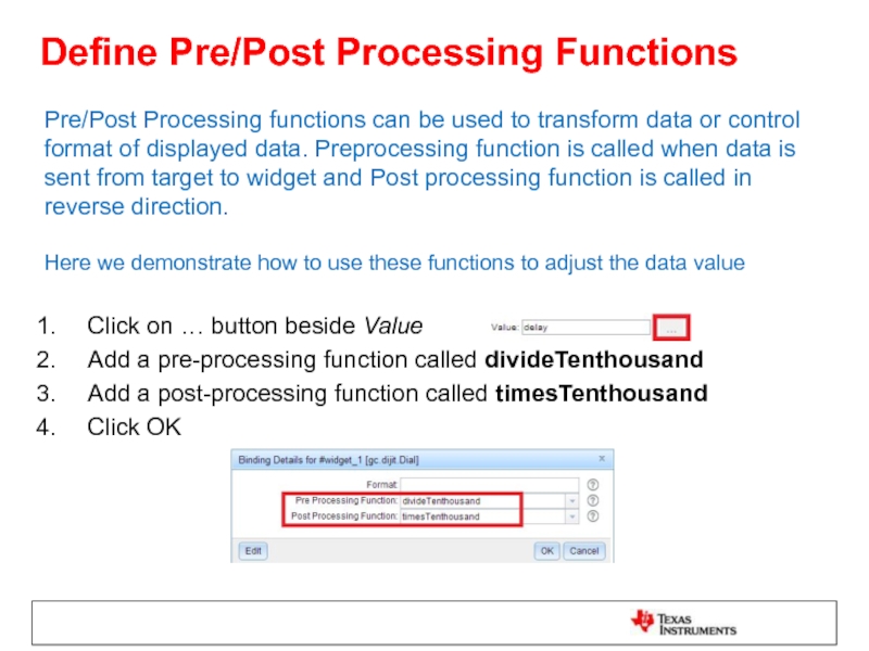
Pre/Post Processing functions can be used to transform
Click on … button beside Value
Add a pre-processing function called divideTenthousand
Add a post-processing function called timesTenthousand
Click OK
Слайд 31Define Pre/Post Processing Functions
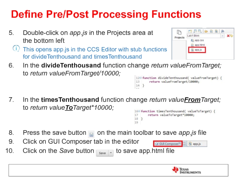
Double-click on app.js in the Projects area at
This opens app.js in the CCS Editor with stub functions for divideTenthousand and timesTenthousand
In the divideTenthousand function change return valueFromTarget; to return valueFromTarget/10000;
In the timesTenthousand function change return valueFromTarget; to return valueToTarget*10000;
Press the save button on the main toolbar to save app.js file
Click on GUI Composer tab in the editor
Click on the Save button to save app.html file
Слайд 32Generate App as a CCS Plug-in
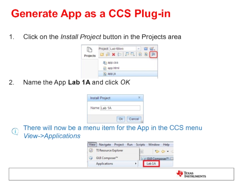
Click on the Install Project button
Name the App Lab 1A and click OK
There will now be a menu item for the App in the CCS menu View->Applications
Слайд 33Load Target Application
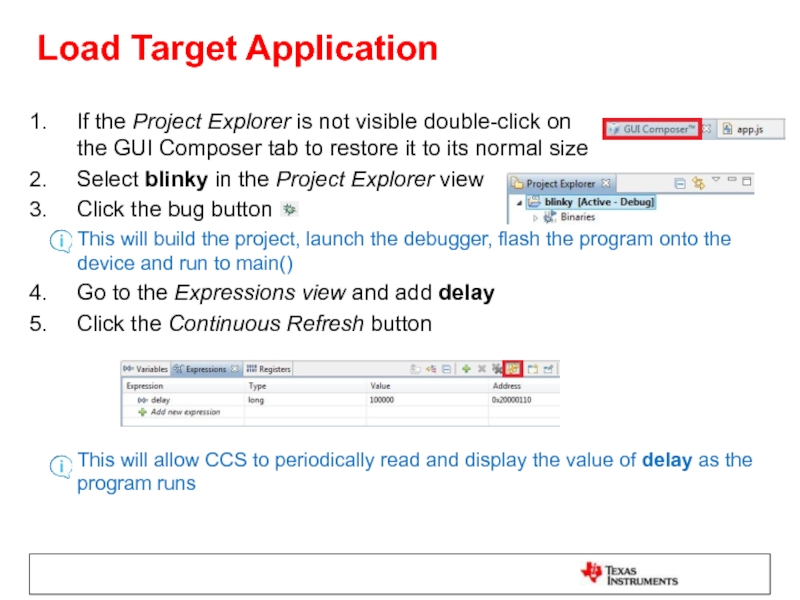
If the Project Explorer is not visible double-click on
Select blinky in the Project Explorer view
Click the bug button
This will build the project, launch the debugger, flash the program onto the device and run to main()
Go to the Expressions view and add delay
Click the Continuous Refresh button
This will allow CCS to periodically read and display the value of delay as the program runs
Слайд 34Preview the App
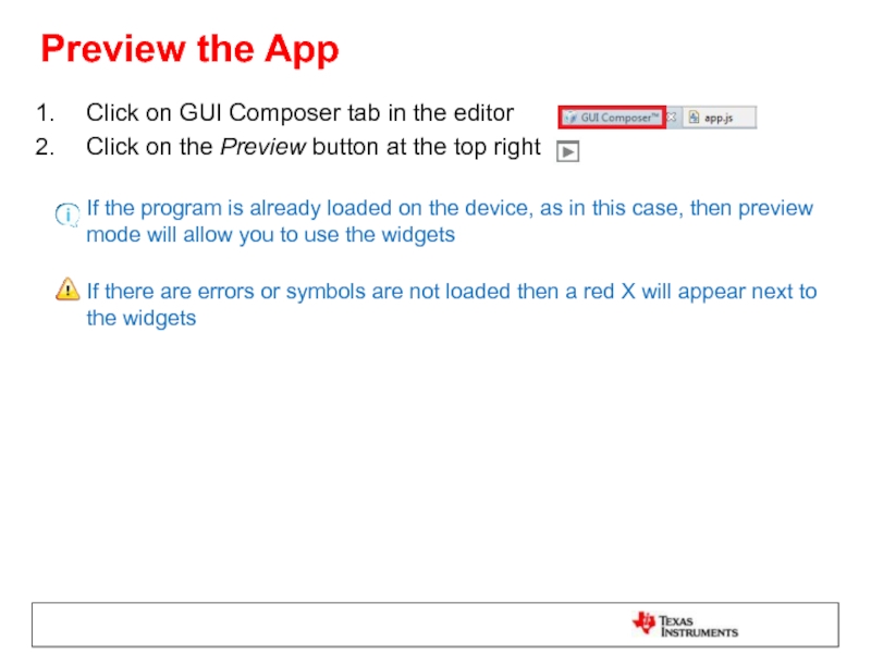
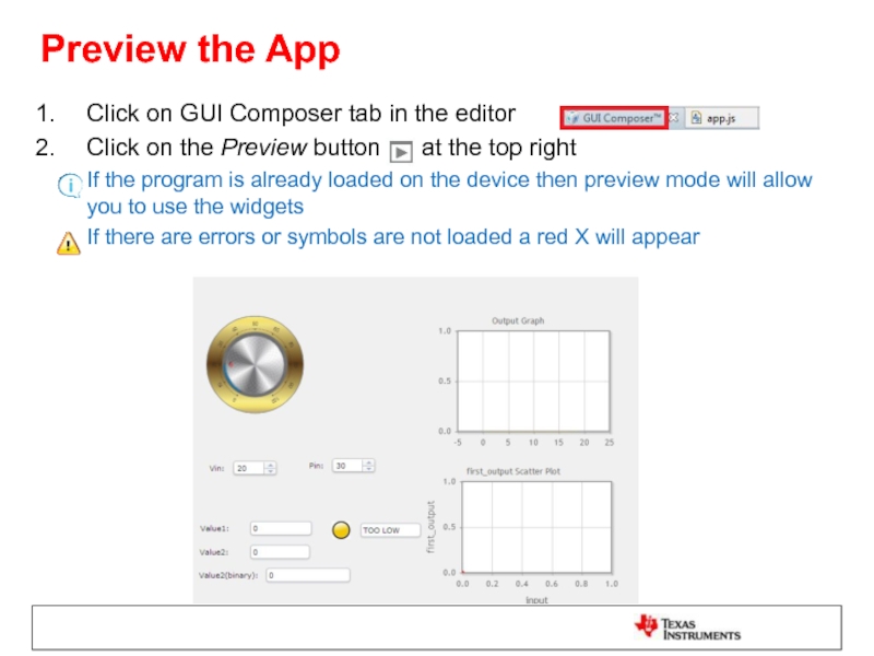
Click on GUI Composer tab in the editor
Click on
If the program is already loaded on the device, as in this case, then preview mode will allow you to use the widgets
If there are errors or symbols are not loaded then a red X will appear next to the widgets
Слайд 35Test the App using Preview Mode
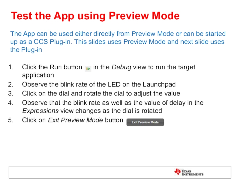
The App can be used either
Click the Run button in the Debug view to run the target application
Observe the blink rate of the LED on the Launchpad
Click on the dial and rotate the dial to adjust the value
Observe that the blink rate as well as the value of delay in the Expressions view changes as the dial is rotated
Click on Exit Preview Mode button
Слайд 36Test the App using Plug-in
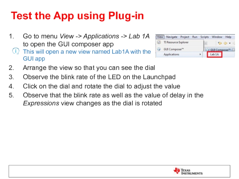
Go to menu View -> Applications ->
Arrange the view so that you can see the dial
Observe the blink rate of the LED on the Launchpad
Click on the dial and rotate the dial to adjust the value
Observe that the blink rate as well as the value of delay in the Expressions view changes as the dial is rotated
Слайд 37Clean Up
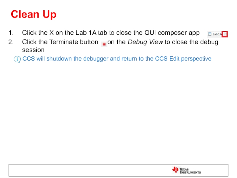
Click the X on the Lab 1A tab to close
Click the Terminate button on the Debug View to close the debug session
CCS will shutdown the debugger and return to the CCS Edit perspective
Слайд 39Modify the Code
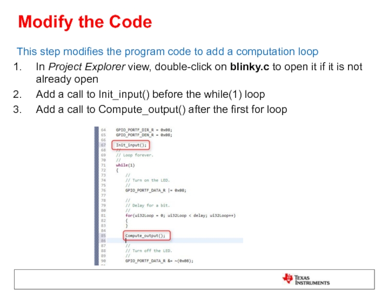
This step modifies the program code to add a
In Project Explorer view, double-click on blinky.c to open it if it is not already open
Add a call to Init_input() before the while(1) loop
Add a call to Compute_output() after the first for loop
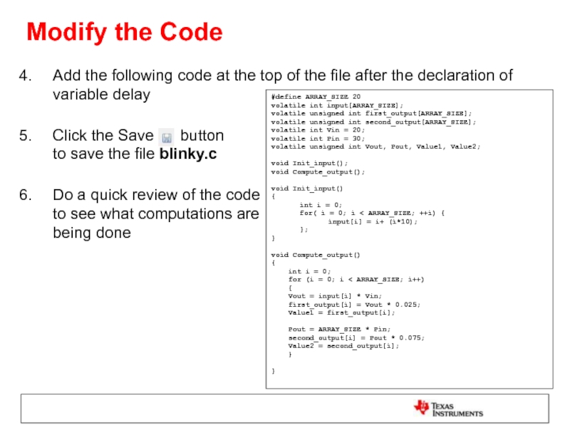
Слайд 40Add the following code at the top of the file after
Click the Save button to save the file blinky.c
Do a quick review of the code to see what computations are being done
Modify the Code
#define ARRAY_SIZE 20
volatile int input[ARRAY_SIZE];
volatile unsigned int first_output[ARRAY_SIZE];
volatile unsigned int second_output[ARRAY_SIZE];
volatile int Vin = 20;
volatile int Pin = 30;
volatile unsigned int Vout, Pout, Value1, Value2;
void Init_input();
void Compute_output();
void Init_input()
{
int i = 0;
for( i = 0; i < ARRAY_SIZE; ++i) {
input[i] = i+ (i*10);
};
}
void Compute_output()
{
int i = 0;
for (i = 0; i < ARRAY_SIZE; i++)
{
Vout = input[i] * Vin;
first_output[i] = Vout * 0.025;
Value1 = first_output[i];
Pout = ARRAY_SIZE * Pin;
second_output[i] = Pout * 0.075;
Value2 = second_output[i];
}
}
Слайд 41Add a Line Graph Widget
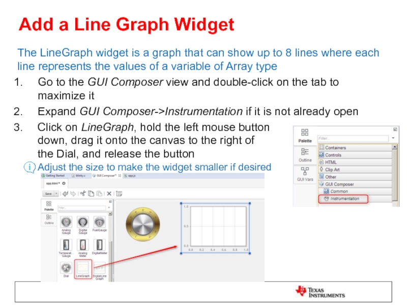
The LineGraph widget is a graph that
Go to the GUI Composer view and double-click on the tab to maximize it
Expand GUI Composer->Instrumentation if it is not already open
Click on LineGraph, hold the left mouse button down, drag it onto the canvas to the right of the Dial, and release the button Adjust the size to make the widget smaller if desired
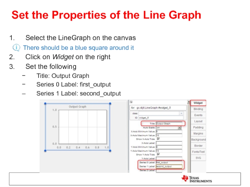
Слайд 42Set the Properties of the Line Graph
Select the LineGraph on the
There should be a blue square around it
Click on Widget on the right
Set the following
Title: Output Graph
Series 0 Label: first_output
Series 1 Label: second_output
Слайд 43Bind Variables to the Line Graph
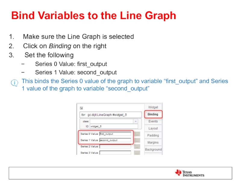
Make sure the Line Graph is
Click on Binding on the right
Set the following
Series 0 Value: first_output
Series 1 Value: second_output
This binds the Series 0 value of the graph to variable “first_output” and Series 1 value of the graph to variable “second_output”
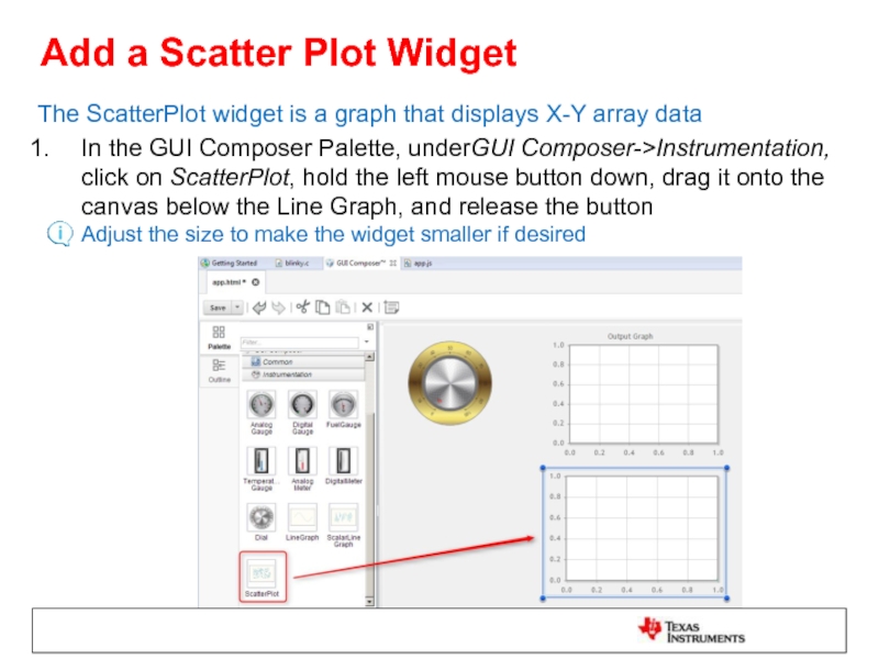
Слайд 44Add a Scatter Plot Widget
The ScatterPlot widget is a graph that
In the GUI Composer Palette, underGUI Composer->Instrumentation, click on ScatterPlot, hold the left mouse button down, drag it onto the canvas below the Line Graph, and release the button Adjust the size to make the widget smaller if desired
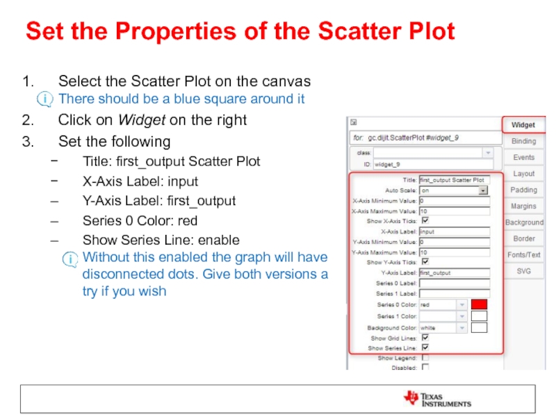
Слайд 45Set the Properties of the Scatter Plot
Select the Scatter Plot on
Click on Widget on the right
Set the following
Title: first_output Scatter Plot
X-Axis Label: input
Y-Axis Label: first_output
Series 0 Color: red
Show Series Line: enable Without this enabled the graph will have disconnected dots. Give both versions a try if you wish
Слайд 46Bind Variables to the Scatter Plot
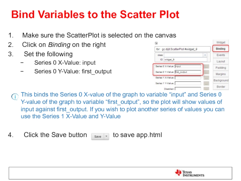
Make sure the ScatterPlot is selected
Click on Binding on the right
Set the following
Series 0 X-Value: input
Series 0 Y-Value: first_output
This binds the Series 0 X-value of the graph to variable “input” and Series 0 Y-value of the graph to variable “first_output”, so the plot will show values of input against first_output. If you wish to plot another series of values you can use the Series 1 X-Value and Y-Value
Click the Save button to save app.html
Слайд 47Add Label Widgets
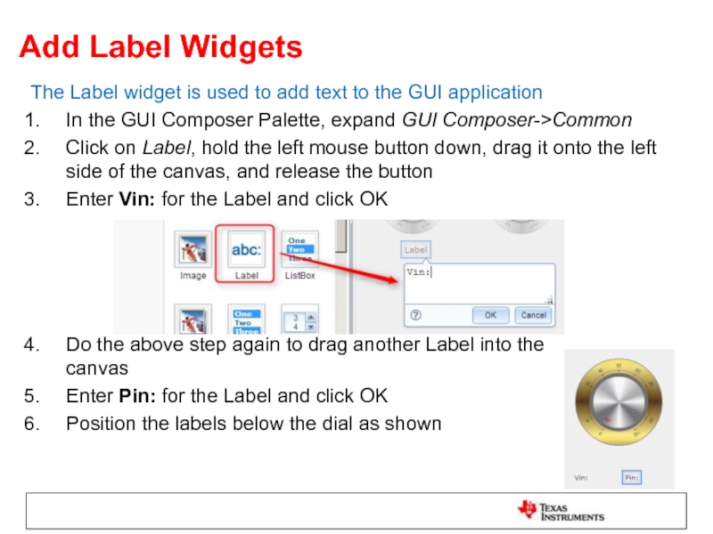
The Label widget is used to add text to
In the GUI Composer Palette, expand GUI Composer->Common
Click on Label, hold the left mouse button down, drag it onto the left side of the canvas, and release the button
Enter Vin: for the Label and click OK
Do the above step again to drag another Label into the canvas
Enter Pin: for the Label and click OK
Position the labels below the dial as shown
Слайд 48Add Number Spinner Widgets
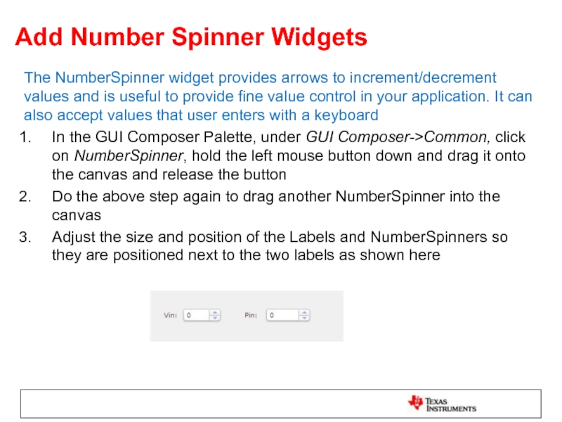
The NumberSpinner widget provides arrows to increment/decrement values
In the GUI Composer Palette, under GUI Composer->Common, click on NumberSpinner, hold the left mouse button down and drag it onto the canvas and release the button
Do the above step again to drag another NumberSpinner into the canvas
Adjust the size and position of the Labels and NumberSpinners so they are positioned next to the two labels as shown here
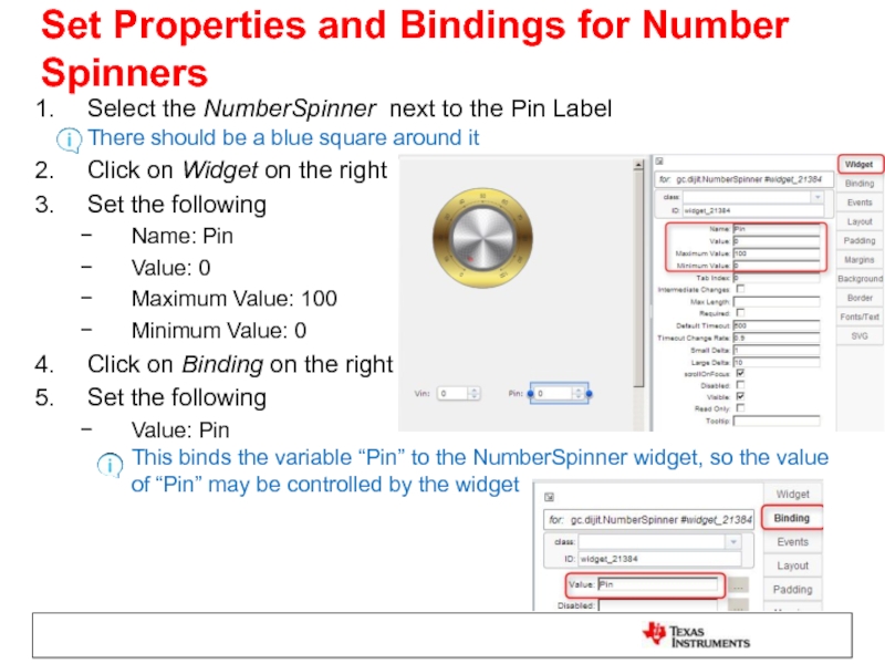
Слайд 49Set Properties and Bindings for Number Spinners
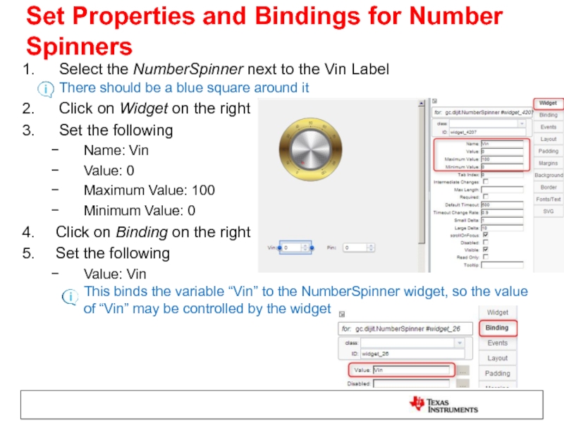
Select the NumberSpinner next to
Click on Widget on the right
Set the following
Name: Vin
Value: 0
Maximum Value: 100
Minimum Value: 0
Click on Binding on the right
Set the following
Value: Vin This binds the variable “Vin” to the NumberSpinner widget, so the value of “Vin” may be controlled by the widget
Слайд 50Set Properties and Bindings for Number Spinners
Select the NumberSpinner next to
Click on Widget on the right
Set the following
Name: Pin
Value: 0
Maximum Value: 100
Minimum Value: 0
Click on Binding on the right
Set the following
Value: Pin This binds the variable “Pin” to the NumberSpinner widget, so the value of “Pin” may be controlled by the widget
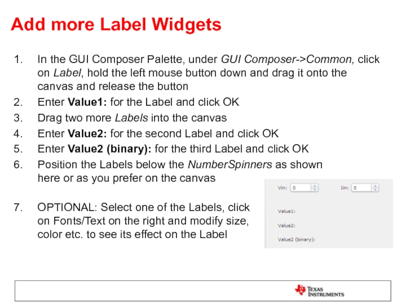
Слайд 51Add more Label Widgets
In the GUI Composer Palette, under GUI Composer->Common,
Enter Value1: for the Label and click OK
Drag two more Labels into the canvas
Enter Value2: for the second Label and click OK
Enter Value2 (binary): for the third Label and click OK
Position the Labels below the NumberSpinners as shown here or as you prefer on the canvas
OPTIONAL: Select one of the Labels, click on Fonts/Text on the right and modify size, color etc. to see its effect on the Label
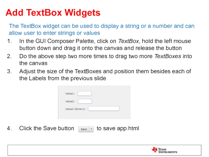
Слайд 52Add TextBox Widgets
The TextBox widget can be used to display a
In the GUI Composer Palette, click on TextBox, hold the left mouse button down and drag it onto the canvas and release the button
Do the above step two more times to drag two more TextBoxes into the canvas
Adjust the size of the TextBoxes and position them besides each of the Labels from the previous slide
Click the Save button to save app.html
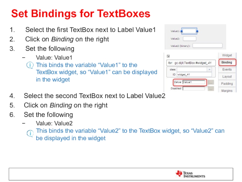
Слайд 53Set Bindings for TextBoxes
Select the first TextBox next to Label Value1
Click
Set the following
Value: Value1 This binds the variable “Value1” to the TextBox widget, so “Value1” can be displayed in the widget
Select the second TextBox next to Label Value2
Click on Binding on the right
Set the following
Value: Value2 This binds the variable “Value2” to the TextBox widget, so “Value2” can be displayed in the widget
Слайд 54Set Bindings for TextBoxes
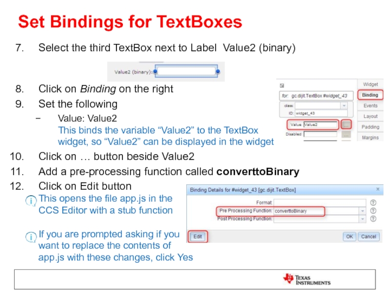
Select the third TextBox next to Label Value2
Click on Binding on the right
Set the following
Value: Value2 This binds the variable “Value2” to the TextBox widget, so “Value2” can be displayed in the widget
Click on … button beside Value2
Add a pre-processing function called converttoBinary
Click on Edit button This opens the file app.js in the CCS Editor with a stub function If you are prompted asking if you want to replace the contents of app.js with these changes, click Yes
Слайд 55Set Bindings for TextBoxes
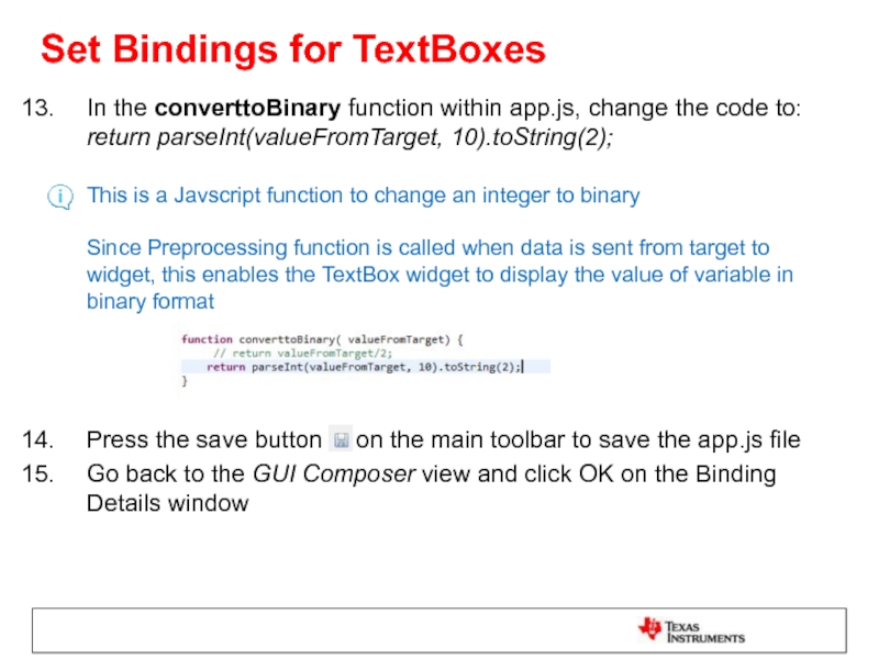
In the converttoBinary function within app.js, change the
Press the save button on the main toolbar to save the app.js file
Go back to the GUI Composer view and click OK on the Binding Details window
Слайд 56Add MultiImage Widget
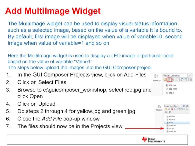
The MultiImage widget can be used to display visual
In the GUI Composer Projects view, click on Add Files
Click on Select Files
Browse to c:\guicomposer_workshop, select red.jpg and click Open
Click on Upload
Do steps 2 through 4 for yellow.jpg and green.jpg
Close the Add File pop-up window
The files should now be in the Projects view
Слайд 57Add MultiImage Widget
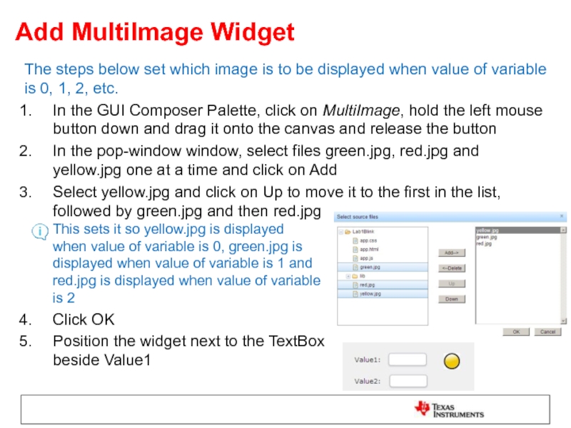
The steps below set which image is to be
In the GUI Composer Palette, click on MultiImage, hold the left mouse button down and drag it onto the canvas and release the button
In the pop-window window, select files green.jpg, red.jpg and yellow.jpg one at a time and click on Add
Select yellow.jpg and click on Up to move it to the first in the list, followed by green.jpg and then red.jpg This sets it so yellow.jpg is displayed when value of variable is 0, green.jpg is displayed when value of variable is 1 and red.jpg is displayed when value of variable is 2
Click OK
Position the widget next to the TextBox beside Value1
Слайд 58Set Binding for MultiImage
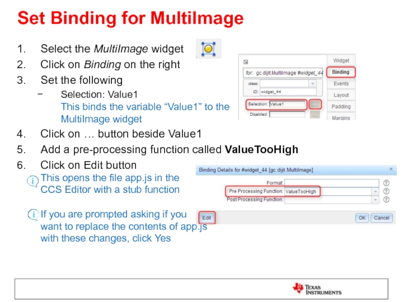
Select the MultiImage widget
Click on Binding on the
Set the following
Selection: Value1 This binds the variable “Value1” to the MultiImage widget
Click on … button beside Value1
Add a pre-processing function called ValueTooHigh
Click on Edit button This opens the file app.js in the CCS Editor with a stub function If you are prompted asking if you want to replace the contents of app.js with these changes, click Yes
Слайд 59Set Binding for MultiImage
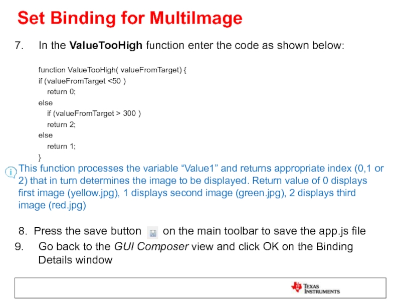
In the ValueTooHigh function enter the code as
if (valueFromTarget <50 )
return 0;
else
if (valueFromTarget > 300 )
return 2;
else
return 1;
} This function processes the variable “Value1” and returns appropriate index (0,1 or 2) that in turn determines the image to be displayed. Return value of 0 displays first image (yellow.jpg), 1 displays second image (green.jpg), 2 displays third image (red.jpg) 8. Press the save button on the main toolbar to save the app.js file
Go back to the GUI Composer view and click OK on the Binding Details window
Слайд 60Add TextBox Widget
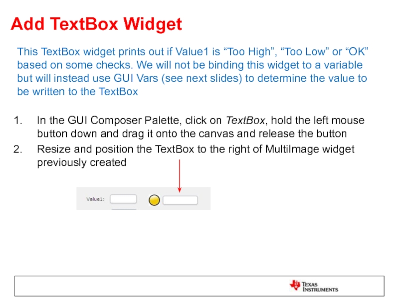
This TextBox widget prints out if Value1 is “Too
In the GUI Composer Palette, click on TextBox, hold the left mouse button down and drag it onto the canvas and release the button
Resize and position the TextBox to the right of MultiImage widget previously created
Слайд 61Add GUI Vars
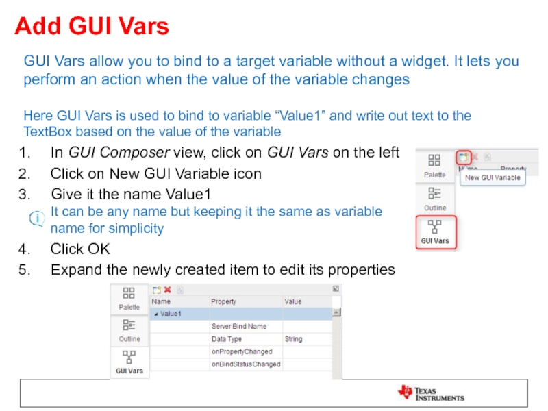
GUI Vars allow you to bind to a target
In GUI Composer view, click on GUI Vars on the left
Click on New GUI Variable icon
Give it the name Value1 It can be any name but keeping it the same as variable name for simplicity
Click OK
Expand the newly created item to edit its properties
Слайд 62Add GUI Vars
For Server Bind Name, click on Value column and
For Data Type, click on Value column and select Long (closest match to your variable type)
For onPropertyChanged, click on Value column
Click on Edit button This opens the file app.js in the CCS Editor with a stub function If you are prompted asking if you want to replace the contents of app.js with these changes, click Yes
Слайд 63Add GUI Vars
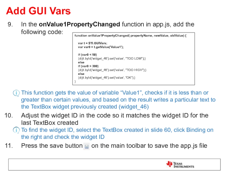
In the onValue1PropertyChanged function in app.js, add the following
Adjust the widget ID in the code so it matches the widget ID for the last TextBox created To find the widget ID, select the TextBox created in slide 60, click Binding on the right and check the widget ID
Press the save button on the main toolbar to save the app.js file
function onValue1PropertyChanged( propertyName, newValue, oldValue) {
var t = $TI.GUIVars;
var var0 = t.getValue('Value1');
if (var0 < 50)
{dijit.byId('widget_46').set('value', "TOO LOW");}
else
if (var0 > 300)
{dijit.byId('widget_46').set('value', "TOO HIGH");}
else
{dijit.byId('widget_46').set('value', "OK");}
}
Слайд 65Load Target Application
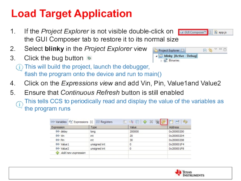
If the Project Explorer is not visible double-click on
Select blinky in the Project Explorer view
Click the bug button
This will build the project, launch the debugger, flash the program onto the device and run to main()
Click on the Expressions view and add Vin, Pin, Value1and Value2
Ensure that Continuous Refresh button is still enabled
This tells CCS to periodically read and display the value of the variables as the program runs
Слайд 66Preview the App
Click on GUI Composer tab in the editor
Click on
If the program is already loaded on the device then preview mode will allow you to use the widgets
If there are errors or symbols are not loaded a red X will appear
Слайд 67Test the App
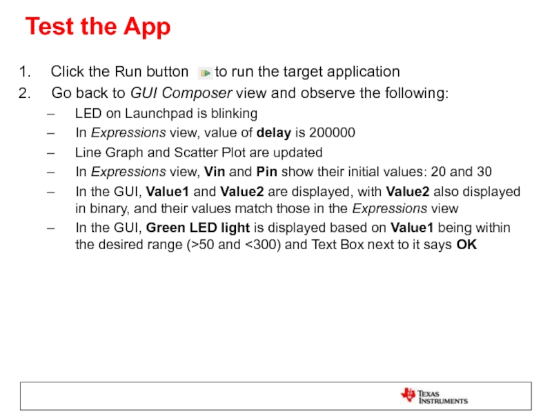
Click the Run button to run the
Go back to GUI Composer view and observe the following:
LED on Launchpad is blinking
In Expressions view, value of delay is 200000
Line Graph and Scatter Plot are updated
In Expressions view, Vin and Pin show their initial values: 20 and 30
In the GUI, Value1 and Value2 are displayed, with Value2 also displayed in binary, and their values match those in the Expressions view
In the GUI, Green LED light is displayed based on Value1 being within the desired range (>50 and <300) and Text Box next to it says OK
Слайд 68Test the App
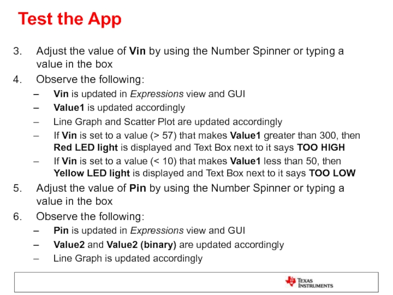
Adjust the value of Vin by using the Number
Observe the following:
Vin is updated in Expressions view and GUI
Value1 is updated accordingly
Line Graph and Scatter Plot are updated accordingly
If Vin is set to a value (> 57) that makes Value1 greater than 300, then Red LED light is displayed and Text Box next to it says TOO HIGH
If Vin is set to a value (< 10) that makes Value1 less than 50, then Yellow LED light is displayed and Text Box next to it says TOO LOW
Adjust the value of Pin by using the Number Spinner or typing a value in the box
Observe the following:
Pin is updated in Expressions view and GUI
Value2 and Value2 (binary) are updated accordingly
Line Graph is updated accordingly
Слайд 69Clean Up
Click on the Exit Preview Mode button
Click the Terminate
CCS will shutdown the debugger and return to the Edit perspective
Слайд 70Exporting the GUI Application
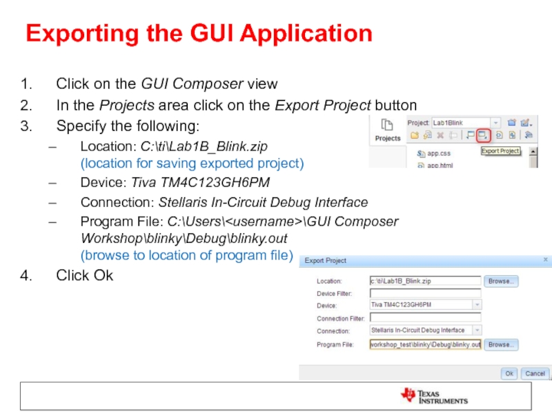
Click on the GUI Composer view
In the Projects
Specify the following:
Location: C:\ti\Lab1B_Blink.zip (location for saving exported project)
Device: Tiva TM4C123GH6PM
Connection: Stellaris In-Circuit Debug Interface
Program File: C:\Users\
Click Ok
Слайд 71Add App to GUI Composer Runtime
Open a file explorer window
Go to
Right click on Lab1B_Blink.zip
Select Extract All
Extract the files to c:\ti\guicomposer\webapps
Слайд 72Run the Standalone Application
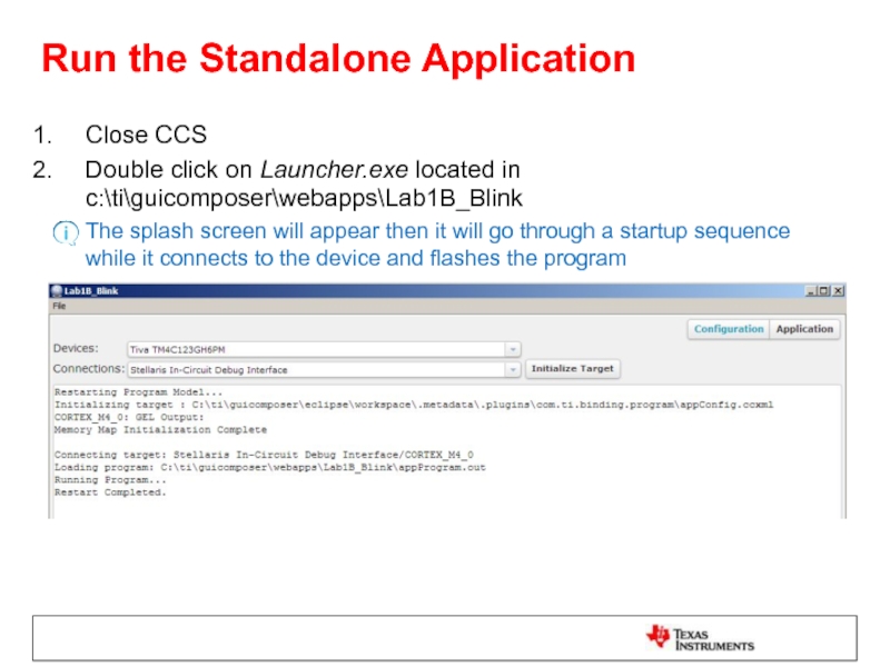
Close CCS
Double click on Launcher.exe located in c:\ti\guicomposer\webapps\Lab1B_Blink
The
Слайд 73Run the Standalone Application
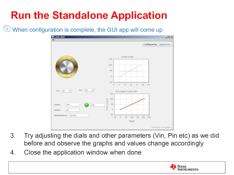
When configuration is complete, the GUI app will
Try adjusting the dials and other parameters (Vin, Pin etc) as we did before and observe the graphs and values change accordingly
Close the application window when done
Слайд 75LAB conventions
Lab steps are numbered for easier reference
…
…
Explanations, notes, warnings are
Warnings are shown with
Information is marked with
Tips and answers are marked with
Questions are marked with
Слайд 76UART Transport: Exercise Summary
Key Objectives
Use a TI-RTOS application with UARTMon module
Create a simple GUI that binds a widget to a target variable
Use UART communication to view and control the application through GUI composer
Tools and Concepts Covered
UART transport using a TI-RTOS application
GUI Builder tool
Variable binding
Target variable modification
Target variable display
NOTE: This lab uses a TI-RTOS program. For using UART communication with a non TI-RTOS program, please refer to this wiki page: http://processors.wiki.ti.com/index.php/ProgramModelUart_GuiComposer
Слайд 78Launch CCS
Double click on the Code Composer Studio desktop icon
Specify “GUI
Слайд 79Import and Build ‘GPIO Interrupt’ Project
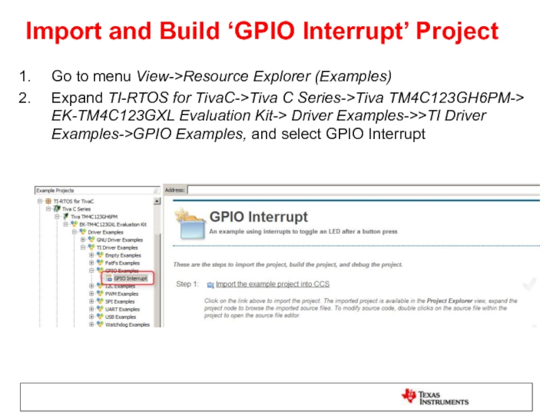
Go to menu View->Resource Explorer (Examples)
Expand
Слайд 80Import and Build ‘GPIO Interrupt’ Project
In the right-pane, click on Step1
Click on Step2 to Build the imported project
Click on Step 3 for Debugger Configuration and select Stellaris In-Circuit Debug Interface as the Connection
Слайд 81Review the RTOS configuration
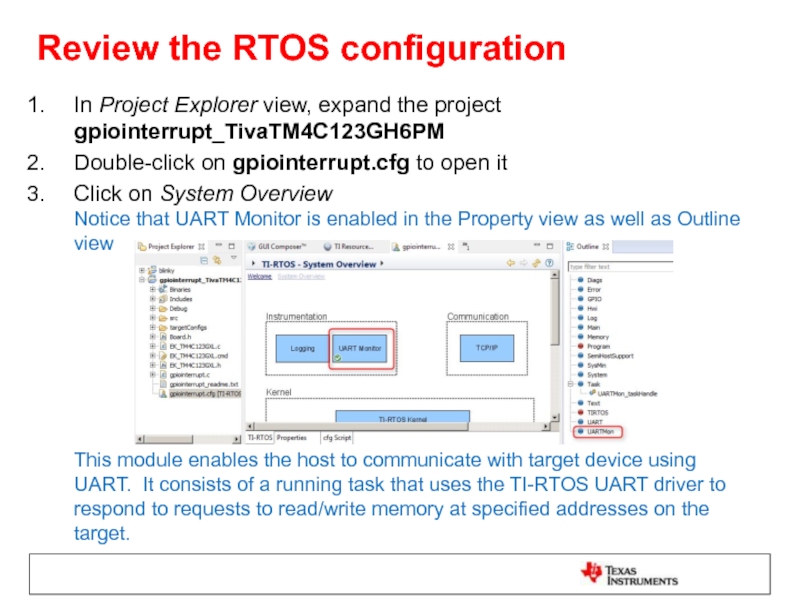
In Project Explorer view, expand the project gpiointerrupt_TivaTM4C123GH6PM
Double-click on gpiointerrupt.cfg to open it
Click on System Overview Notice that UART Monitor is enabled in the Property view as well as Outline view This module enables the host to communicate with target device using UART. It consists of a running task that uses the TI-RTOS UART driver to respond to requests to read/write memory at specified addresses on the target.
Слайд 82Add UART Communication to target config
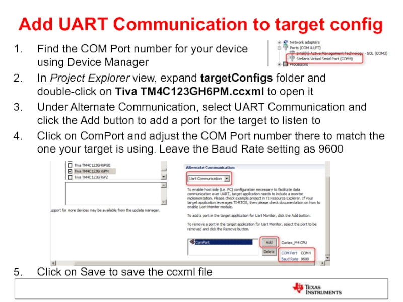
Find the COM Port number for
In Project Explorer view, expand targetConfigs folder and double-click on Tiva TM4C123GH6PM.ccxml to open it
Under Alternate Communication, select UART Communication and click the Add button to add a port for the target to listen to
Click on ComPort and adjust the COM Port number there to match the one your target is using. Leave the Baud Rate setting as 9600
Click on Save to save the ccxml file
Слайд 83Open GUI Composer
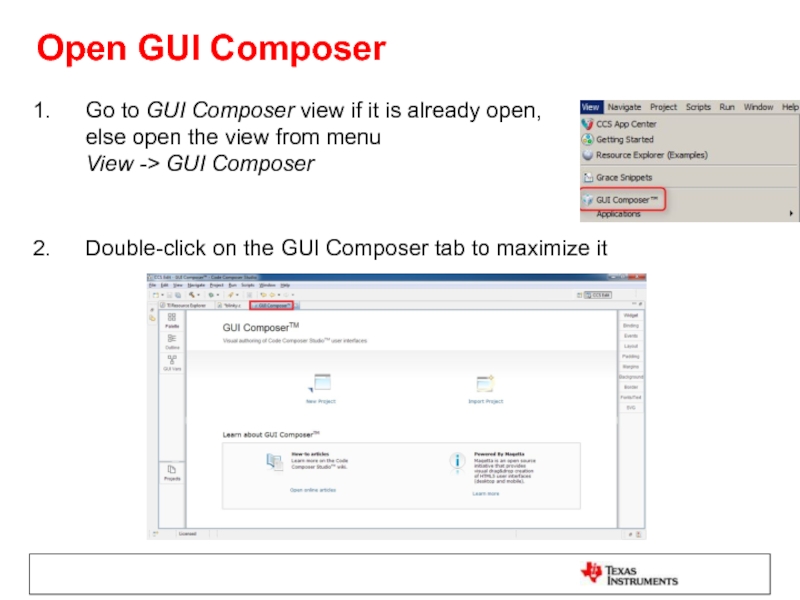
Go to GUI Composer view if it is already
Double-click on the GUI Composer tab to maximize it
Слайд 84Create a New GUI Composer Project
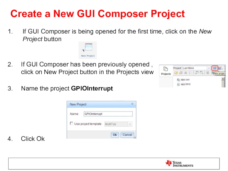
If GUI Composer is being opened
If GUI Composer has been previously opened , click on New Project button in the Projects view
Name the project GPIOInterrupt
Click Ok
Слайд 85Add a Dial Widget
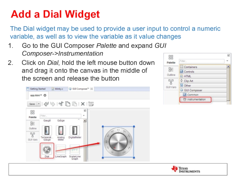
The Dial widget may be used to provide
Go to the GUI Composer Palette and expand GUI Composer->Instrumentation
Click on Dial, hold the left mouse button down and drag it onto the canvas in the middle of the screen and release the button
Слайд 86Change the Appearance of the Dial
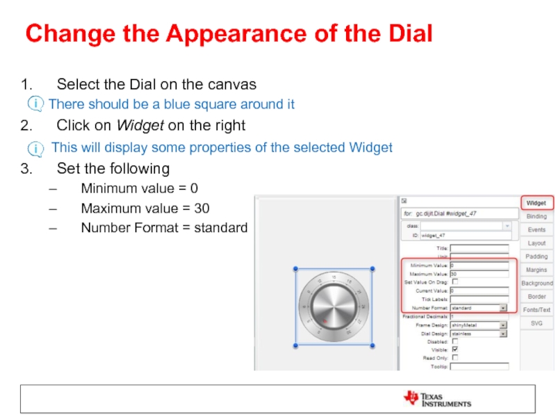
Select the Dial on the canvas
Click on Widget on the right
This will display some properties of the selected Widget
Set the following
Minimum value = 0
Maximum value = 30
Number Format = standard
Слайд 87Bind a Variable to the Dial
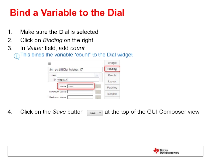
Make sure the Dial is selected
Click
In Value: field, add count This binds the variable “count” to the Dial widget
Click on the Save button at the top of the GUI Composer view
Слайд 88Load Target Application
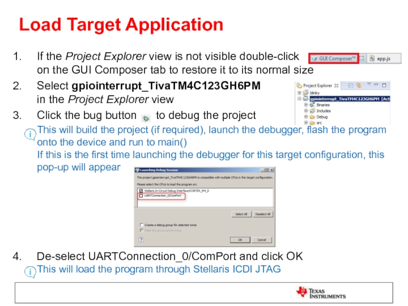
If the Project Explorer view is not visible double-click
Select gpiointerrupt_TivaTM4C123GH6PM in the Project Explorer view
Click the bug button to debug the project
This will build the project (if required), launch the debugger, flash the program onto the device and run to main() If this is the first time launching the debugger for this target configuration, this pop-up will appear
De-select UARTConnection_0/ComPort and click OK This will load the program through Stellaris ICDI JTAG
Слайд 89Load Symbols for UART Connection
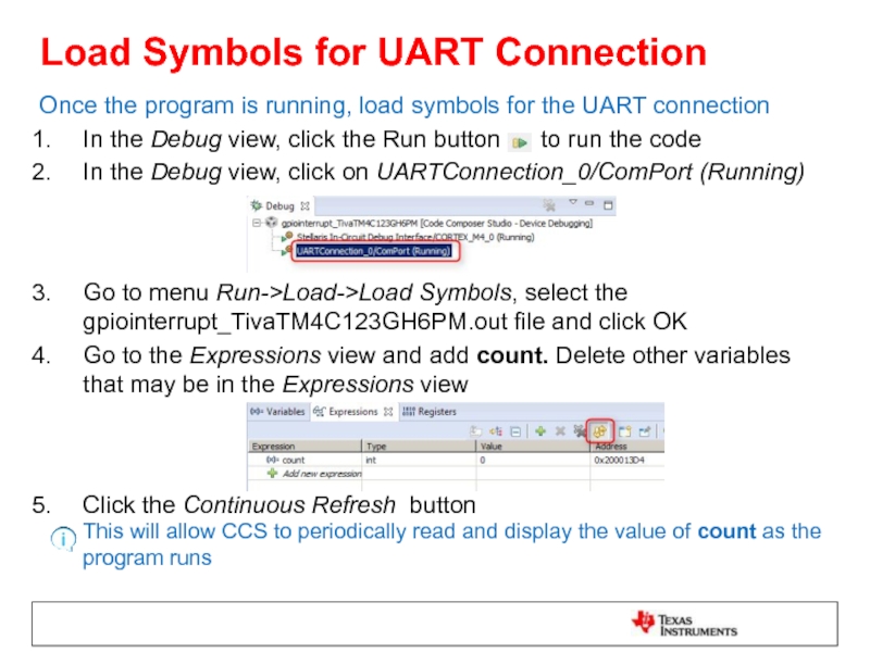
Once the program is running, load symbols
In the Debug view, click the Run button to run the code
In the Debug view, click on UARTConnection_0/ComPort (Running)
Go to menu Run->Load->Load Symbols, select the gpiointerrupt_TivaTM4C123GH6PM.out file and click OK
Go to the Expressions view and add count. Delete other variables that may be in the Expressions view
Click the Continuous Refresh button This will allow CCS to periodically read and display the value of count as the program runs
Слайд 90Preview the App
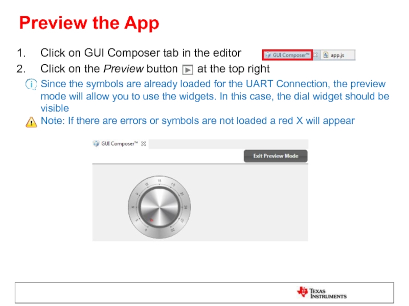
Click on GUI Composer tab in the editor
Click on
Since the symbols are already loaded for the UART Connection, the preview mode will allow you to use the widgets. In this case, the dial widget should be visible Note: If there are errors or symbols are not loaded a red X will appear
Слайд 91Test the App
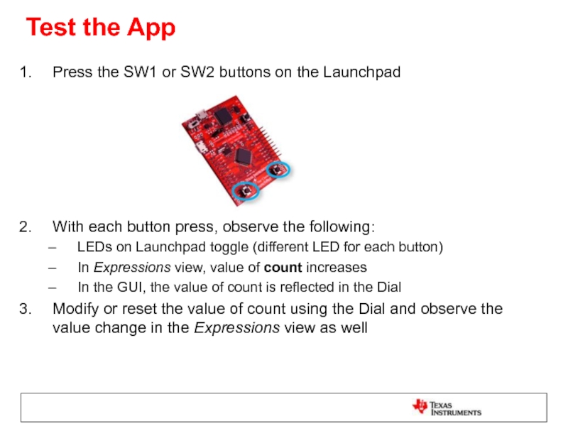
Press the SW1 or SW2 buttons on the Launchpad
With
LEDs on Launchpad toggle (different LED for each button)
In Expressions view, value of count increases
In the GUI, the value of count is reflected in the Dial
Modify or reset the value of count using the Dial and observe the value change in the Expressions view as well
Слайд 92Clean Up
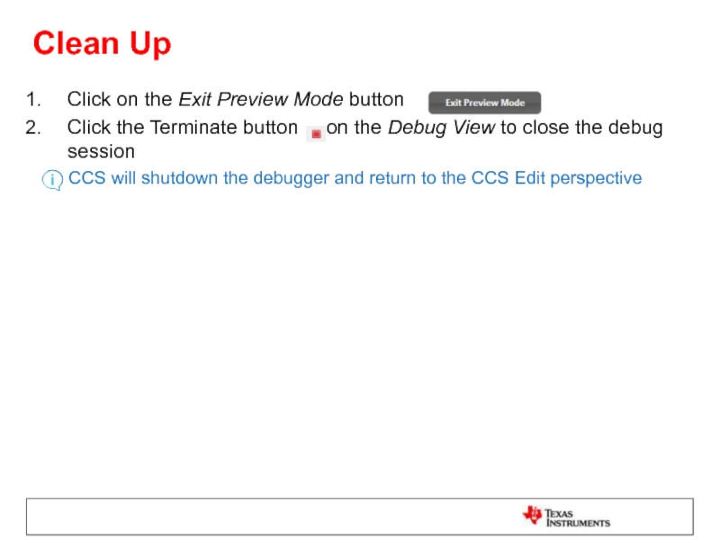
Click on the Exit Preview Mode button
Click the Terminate
CCS will shutdown the debugger and return to the CCS Edit perspective
Слайд 93Exporting the GUI Application
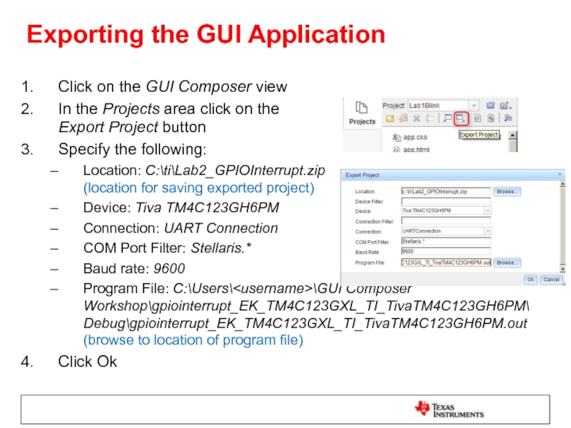
Click on the GUI Composer view
In the Projects
Specify the following:
Location: C:\ti\Lab2_GPIOInterrupt.zip (location for saving exported project)
Device: Tiva TM4C123GH6PM
Connection: UART Connection
COM Port Filter: Stellaris.*
Baud rate: 9600
Program File: C:\Users\
Click Ok
Слайд 94Add App to GUI Composer Runtime
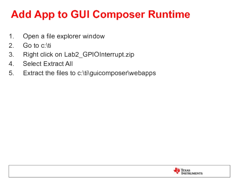
Open a file explorer window
Go to
Right click on Lab2_GPIOInterrupt.zip
Select Extract All
Extract the files to c:\ti\guicomposer\webapps
Слайд 95Run the Standalone Application
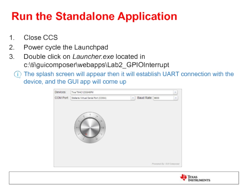
Close CCS
Power cycle the Launchpad
Double click on Launcher.exe
The splash screen will appear then it will establish UART connection with the device, and the GUI app will come up
Слайд 96Test the Standalone Application
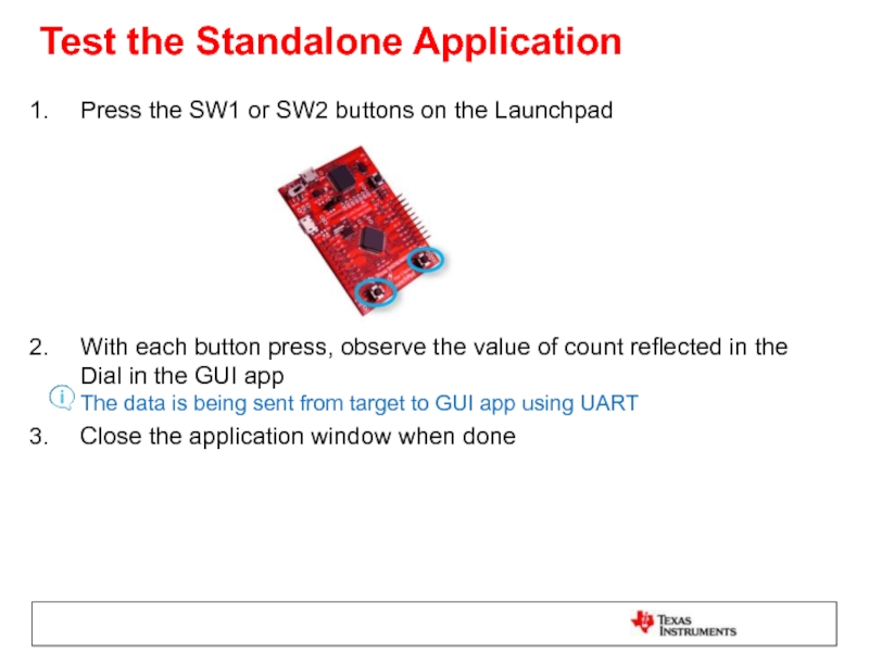
Press the SW1 or SW2 buttons on the
With each button press, observe the value of count reflected in the Dial in the GUI app The data is being sent from target to GUI app using UART
Close the application window when done
Слайд 97Exercise Summary
After completing the labs you should be familiar with:
Using GUI
Running GUI Composer app from within CCS or standalone
Using JTAG and UART transport for viewing and controlling the application through GUI composer
Additional References:
GUI Composer wiki: http://processors.wiki.ti.com/index.php/Category:GUI_Composer
