- Главная
- Разное
- Дизайн
- Бизнес и предпринимательство
- Аналитика
- Образование
- Развлечения
- Красота и здоровье
- Финансы
- Государство
- Путешествия
- Спорт
- Недвижимость
- Армия
- Графика
- Культурология
- Еда и кулинария
- Лингвистика
- Английский язык
- Астрономия
- Алгебра
- Биология
- География
- Детские презентации
- Информатика
- История
- Литература
- Маркетинг
- Математика
- Медицина
- Менеджмент
- Музыка
- МХК
- Немецкий язык
- ОБЖ
- Обществознание
- Окружающий мир
- Педагогика
- Русский язык
- Технология
- Физика
- Философия
- Химия
- Шаблоны, картинки для презентаций
- Экология
- Экономика
- Юриспруденция
Electrical menu презентация
Содержание
- 1. Electrical menu
- 2. The A320 electrical system looks very
- 3. There are two engine
- 4. The generators maintain a constant speed
- 5. Each generator supplies Alternating Current (AC)
- 7. Each AC bus supplies its
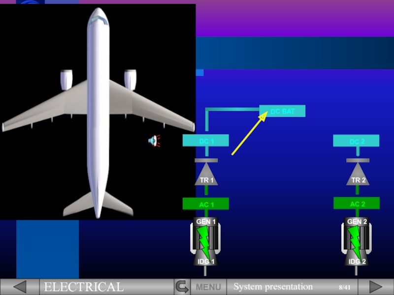
- 9. DC bus 1 then, feeds the
- 10. DC BAT
- 11. This is the basic electrical system.
- 12. The electrical network can also be
- 13. These three generators are all identical
- 14. DC BAT
- 15. As a backup, there is
- 16. The hydraulic power to drive the
- 17. DC BAT
- 18. Now, let's see how this information
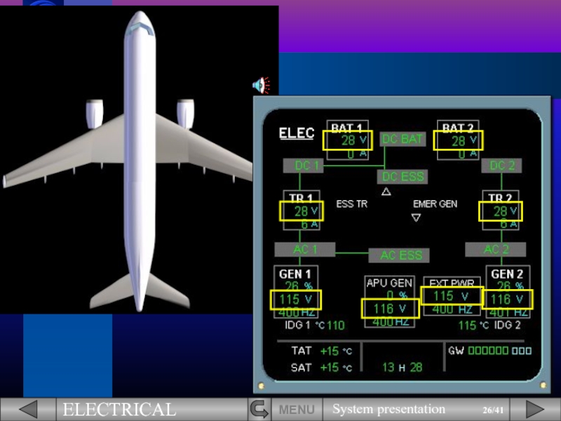
- 19. You can see that all the
- 20. GEN 1 and GEN 2 supplying
- 21. TR 1 and TR 2 supplying
- 22. Two essential busses supplied by the
- 23. The DC BAT bus and two
- 24. For simplification the component indications have
- 25. As shown, each component can be
- 29. MENU
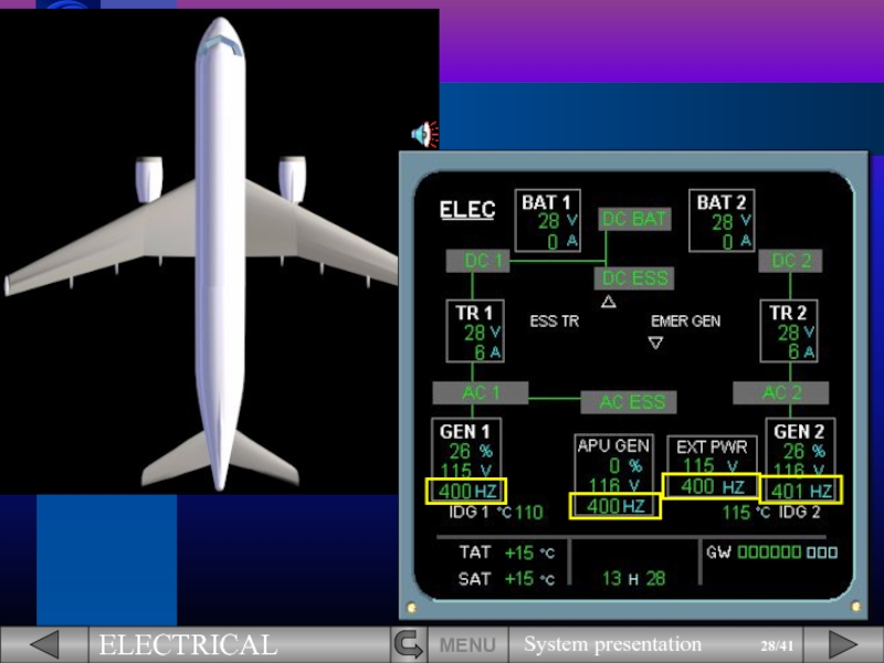
- 30. You can also notice the different
- 31. The ELEC panel is located on
- 32. For emergency cases, there is
- 33. The battery voltage can be monitored
- 34. Each battery is controlled by a
- 35. Both main generators and the APU
- 36. The external power is also controlled
- 37. The AC ESS FEED pb sw
- 38. The BUS TIE pb sw enables
- 39. In case of failure, these pb
- 40. MENU
- 41. In this module, you have seen
- 42. LIST OF SUBJECTS MENU

Слайд 2
The A320 electrical system looks very much like electrical systems which
MENU


Слайд 4
The generators maintain a constant speed by a drive mechanism known
IDG 1
IDG 2
MENU

Слайд 5
Each generator supplies Alternating Current (AC) to its own bus:
Generator 1
Generator 2 to AC bus 2.
MENU
 to its own bus:Generator 1 to AC bus 1,Generator")

Слайд 7
Each AC bus supplies its own Transformer Rectifier (TR):
AC bus 1
AC bus 2 to TR 2.
The TR convert alternating current into direct current (DC) to supply their associated DC buses, DC 1 and DC 2.
MENU
:AC bus 1 to TR 1,AC bus")
Слайд 9
DC bus 1 then, feeds the DC BAT bus (DC BAT).
The
MENU
.The DC battery bus can")
Слайд 10
DC BAT
The electrical system also includes two essential buses.
The first one
MENU

Слайд 11
This is the basic electrical system.
We will now introduce some
DC BAT
MENU


Слайд 13
These three generators are all identical and any one of them
DC BAT
MENU


Слайд 15
As a backup, there is a hydraulically driven EMERgency electrical GENerator
MENU
DC BAT
.MENUDC BAT")
Слайд 16
The hydraulic power to drive the EMER GEN is provided by
MENU
DC BAT

Слайд 17
DC BAT
The electrical system is also fitted with an ESSential Transformer
We will see the EMER GEN and the ESS TR in detail in the Abnormal operation module.
MENU
.We will")
Слайд 18
Now, let's see how this information is presented to the pilots
We will introduce the ECAM ELEC page.
DC BAT
MENU

Слайд 19
You can see that all the components we have talked about
Let’s briefly review the basic system using the ECAM ELEC page.
DC BAT
MENU


Слайд 30
You can also notice the different connections displayed via green lines.
Let’s now locate the various controls available to the pilots and associate them with the components displayed on the ECAM.
MENU


Слайд 32
For emergency cases, there is an EMER ELEC PWR panel on
Now let’s look at the relationship between the ELEC panel and the ECAM ELEC page.
MENU


Слайд 36
The external power is also controlled by a pb sw.
We will
MENU

Слайд 37
The AC ESS FEED pb sw enables the pilots to change
MENU

Слайд 38
The BUS TIE pb sw enables the pilots to isolate one
MENU


Слайд 40
MENU
The controls and indications on the EMER ELEC PWR panel will
There is one exception. The EMER GEN TEST sw is used by maintenance only to test the emergency generator.

Слайд 41
In this module, you have seen the electrical configuration on ground,
We will introduce you to the different possible configurations in the next modules.
NEXT
MENU
Module completed

Слайд 42
LIST OF SUBJECTS
MENU
EXIT
GLOSSARY
AUDIO
FCOM
RETURN
SYSTEM INTRODUCTION
ECAM ELEC PAGE
EMER ELEC PWR PANEL
PANEL LOCATIONS
ELEC