CO-DESIGN AND TESTING
OF SAFETY-CRITICAL
EMBEDDED SYSTEMS
Master Course
CO-DESIGN AND TESTING
OF SAFETY-CRITICAL
EMBEDDED SYSTEMS
Master Course

3. Subject of Study:
Principles, methods and techniques in co-design and testing of S-CES.
4. Aims:
Acquisition of knowledge about methods and techniques in co-design and testing of S-CES and their components.
Object of Study:
Concepts of Safety-Critical Embedded Systems (S-CES): Co-design and Testing.
Master Course. Co-Design and Testing of Safety-Critical Embedded Systems

3


1.2. Standards regulating legislative of S-CES
1.3. Life-cycle of S-CES
1.1. Component approach
Master Course. Co-Design and Testing of Safety-Critical Embedded Systems

COTS-approach (Commercial-Off-The-Shelf) – reuse of commercial components.
CrOTS-approach (Critical-Off-The-Shelf) – reuse of components in critical applications.
Component approach constitutes the use of library components developed formerly and commonly employed in commercial and critical applications, including the components of one’s own design.
Master Course. Co-Design and Testing of Safety-Critical Embedded Systems

Master Course. Co-Design and Testing of Safety-Critical Embedded Systems
DO 178-B (Avionics)
and
ISO 26262 (Automotive)
IEC 61513
(Nuclear power plants)
and
IEC 62061 (Machines)
IEC – International Electrotechnical Commission
This slide from presentation of M. Fusani ISTI - CNR, Pisa, Italy
 and EN")
Master Course. Co-Design and Testing of Safety-Critical Embedded Systems
IEC 61508-1:1998 ‘General requirements’
IEC 61508-2:2000 ‘Requirements to electrical, electronic and programmable systems’
IEC 61508-3:1998 ‘Requirements to software’
IEC 61508-4:1998 ‘Definitions to Abbreviations’
IEC 61508-5:1998 ‘Examples of methods for determining safety integrity levels’
IEC 61508-6:2000 ‘Guide for use of IEC 61508-2 and IEC 61508-3’
IEC 61508-7:2000 ‘Overview of techniques and measures’

1. The use of safety integrity levels concept – every unit of equipment is developed and analysed with contribution in safety of critical object.
2. Consideration of full life-cycle of S-CES
3. Positioning of software as essential S-CES component which is source of possible failures influencing on safety of critical object
4. Flexibility of requirements for the critical objects. It allows to be foundation for development of standards to specific areas of industry

Master Course. Co-Design and Testing of Safety-Critical Embedded Systems
ECSS – European Cooperation for Space Standardization
ECSS-E-10 ‘Space Engineering – System Development’
ECSS-E-40A ‘Space Engineering – Software Development’
ECSS-Q-20 ‘Guarantee Production Space Destination – Quality Assurance’
ECSS-Q-80B ‘Guarantee Production Space Destination – Quality Assurance of Software’

Master Course. Co-Design and Testing of Safety-Critical Embedded Systems
RTCA – Radio Technical Commission for Aeronautics
DO-178B:1992 ‘Consideration of software at certification of
on-board systems and equipments’
MIRA – Motor Industry Research Association
MISRA-C:2004 ‘Guide for use of language C++ in critical systems‘
CENELEC – European Committee for Electrotechnical Standardization
EN 50126 ‘Objects of railway transport. Requirements and validation of dependability, reliability, maintainability and safety‘

Master Course. Co-Design and Testing of Safety-Critical Embedded Systems
IAEA – International Atomic Energy Agency
IAEA NS-G-1.1 ‘Software and computer-based systems important to safety in nuclear power plants’
IAEA NS-G-1.2 ‘Safety assessment and verification for nuclear power plants’
IAEA NS-G-1.3 ‘Instrumentation and control systems important to safety in nuclear power plants’

Master Course. Co-Design and Testing of Safety-Critical Embedded Systems
IEC – International Technical Commission
IEC 60780:1998 ‘Nuclear power plants – Electrical equipment of the safety system - Qualification’
IEC 60880:2006 ‘Nuclear power plants – Instrumentation and control systems important to safety – Software aspects for computer-based systems performing category A functions’
IEC 60980:1989 ‘Recommended practices for seismic qualification of electrical equipment of the safety system for nuclear generating stations’
IEC 60987:2007 ‘Nuclear power plants – Instrumentation and control systems important to safety – Hardware design requirements for computer-based systems’

Master Course. Co-Design and Testing of Safety-Critical Embedded Systems
IEC – International Technical Commission
IEC 61226:2005 ‘Nuclear power plants – Instrumentation and control systems important to safety – Classification of instrumentation and control functions’
IEC 61513:2001 ‘Nuclear power plants – Instrumentation and control systems important to safety – General requirements for systems’
IEC 62138:2004 ‘Nuclear power plants – Instrumentation and control systems important to safety – Software aspects for computer-based systems performing category B or C functions’
IEC 62340:2007 ‘Nuclear power plants – Instrumentation and control systems important to safety – Requirements for coping with common cause failure’

Master Course. Co-Design and Testing of Safety-Critical Embedded Systems
2. Development of program models of control algorithms in CASE-tools environment.
3. Integration of signal formation algorithm block-diagram program models in CASE-tools environment.
4. Implementation of integrated digital component program models to FPGA.
CASE – Computer Aided Software / System Engineering

Master Course. Co-Design and Testing of Safety-Critical Embedded Systems
2. Program models of control algorithms in CASE-tools environment.
3. Integrated program model of control algorithms in CASE-tools environment.
4. FPGA with implemented integrated program model.

Master Course. Co-Design and Testing of Safety-Critical Embedded Systems
2. Verification of program models of control algorithms in CASE-tools environment.
3. Verification of integrated program model in CASE-tools environment.
4. Verification of FPGA with implemented integrated program model.


1. Co-design of S-CES is based on traditional ideas such as Component approach, Standards regulating legislative and Life-cycle of S-CES
Master Course. Co-Design and Testing of Safety-Critical Embedded Systems
3. The main standard is IEC 61508 – Safety of electrical, electronic and programmable systems important to safety.
4. Life-cycle of FPGA-based S-CES digital component contains 4 stages of development with verification of results obtained on every stage.

Master Course. Co-Design and Testing of Safety-Critical Embedded Systems

22

2.2. Dependability Threats
2.3. Dependability Attributes
2.1. Introduction into dependability
Master Course. Co-Design and Testing of Safety-Critical Embedded Systems
2.4. Dependability Measures
2.5. Safety and Reliability
2.6. Forms of Dependability Requirements
2.7. The Means to attain Dependability Techniques

Growth of computer system complexity
Master Course. Co-Design and Testing of Safety-Critical Embedded Systems
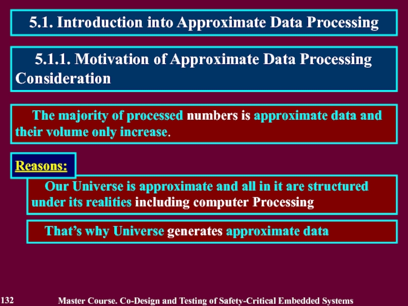
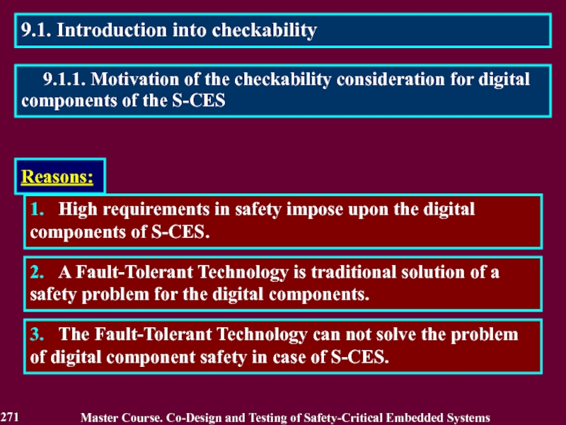
2.1.1. Motivation of Dependability Consideration
Expansion of a set of tasks solved with use of computer systems including critical application areas
Amplification of interdependence and interaction between hardware and software of computer systems including processes of co-design S-CES on programmable elements.
Reasons:

1. Avizienis A., Laprie J.-C. Dependable Computing: From Concepts to Application // IEEE Transactions on Computers, 1986. Vol. 74, No. 5. P. 629-638.
Authors formulated the principle of “Dependable Computing” as computation resistant to hardware and software failures (caused by their defects brought in design and not revealed in the course of detected).
Master Course. Co-Design and Testing of Safety-Critical Embedded Systems
2. Dobson I., Randell B. Building Reliable Secure Computing Systems out of Unreliable Insecure components // Proc. of IEEE Conference on Security and Privacy, Oakland, USA. 1986. P. 186-193.
Authors defined “Secure-Fault Tolerance” and proposed a principle of its realization for various types of computer systems.
3. Avizienis A., Laprie J.-C, Randell B., Landwehr C. Basic Concepts and Taxonomy of Dependable and Secure Computing // IEEE Transactions on Dependable and Secure Computing, 2004. Vol. 1. No. 1. P. 11-33.

Attributes - properties expected from the system and according to which assessment of service quality resulting from threats and means opposing to them is conducted.
Means - methods and techniques enabling
to provide service on which reliance can be placed
to have confidence in its ability.
Master Course. Co-Design and Testing of Safety-Critical Embedded Systems
Threats - undesired (not unexpected) circumstances causing or resulting from undependability (reliance cannot or will not any longer be placed on the service.

Master Course. Co-Design and Testing of Safety-Critical Embedded Systems
Faults: development ( design) or operational (phase of creation or occurrence),
internal or external (system boundaries),
hardware or software (domain),
natural or human-made (phenomenological case), accidental, non-malicious, deliberate or deliberately malicious (intent),
permanent or transient (persistence).

Faults: Development or Design Faults
Physical Faults
Interaction Faults
Development or Design Faults:
erroneous acts or decisions in system development bring to appearance of a fault in its design which becomes apparent in computer system operation under certain terms and causes an error in computation process, thus leading to a malfunction or failure (non-rendering of service)
software flaws,
malicious logics.

Physical Faults:
due to natural (internal) causes a fault appears bringing to an error in computation process, thus leading to a malfunction or failure.
Interaction Faults:
due to external information, physical or other effects a fault appears bringing to an error in computation process and then a computer system malfunction or failure.

Failures: content, early or late timing,
halt or erratic (domain),
signaled or unsignaled (detectability),
consistent or inconsistent (consistency),
minor or catastrophic (consequences).

Master Course. Co-Design and Testing of Safety-Critical Embedded Systems
This slide from presentation of Felicita Di Giandomenico ISTI - CNR, Pisa, Italy

Absence of catastrophic consequences on the users & env. – Safety.
Master Course. Co-Design and Testing of Safety-Critical Embedded Systems
Availability, Confidentiality, Integrity – Security.
Absence of unauthorized access to, or handling of, system state.
Absence of unauthorized disclosure of inf. – Confidentiality.
Absence of improper system alterations – Integrity.
Ability to undergo repairs and evolutions – Maintainability.

Reliability: a measure of the continuous delivery of correct service – or the time to failure;
Master Course. Co-Design and Testing of Safety-Critical Embedded Systems
Maintainability: a measure of the time to service restoration since the last failure occurrence.
Availability: a measure of the delivery of correct service with respect to the alternation of correct and incorrect service;

• Safety is a measure of continuous safeness, or equivalently, of the time to catastrophic failure;
Master Course. Co-Design and Testing of Safety-Critical Embedded Systems
• Safety is thus Reliability with respect to catastrophic failures.

Master Course. Co-Design and Testing of Safety-Critical Embedded Systems
Other forms of requirements:
Fault tolerance: this system must provide uninterrupted service with up to one component failure, and fail safely if two fail;
Specific defensive mechanisms: "these data shall be held in duplicate on two disks.
Rate of occurrence of failures: – "the probability that a failure of a flight control system will cause an accident with fatalities or loss of aircraft must be less than 10-9 per hour of flight“.
Probability of surviving mission: – The probability that the flight and ordnance control system in a fighter plane are still operational at the end of a two hour mission must be more than...

• Fault prevention: how to prevent the occurrence or introduction of faults;
Master Course. Co-Design and Testing of Safety-Critical Embedded Systems
• Fault removal: how to reduce the number or severity of faults;
• Fault forecasting: how to estimate the present number, the future incidence and the likely consequences of faults.
• Fault tolerance: how to deliver correct service in the presence of faults.

• They include structured programming, information hiding, modularization, etc., for software, and rigorous design rules and selection of high-quality, mass-manufactured hardware components for hardware.
Master Course. Co-Design and Testing of Safety-Critical Embedded Systems
• Simple design, possibly at the cost of constraining functionality or increasing cost
• Formal proof of important properties of the design
• Provision of appropriate operating environment (air conditioning, protection against mechanical damage) intend to prevent operational physical faults, while training, rigorous procedures for maintenance, ‘foolproof’ packages, intend to prevent interaction faults.

• During development it consists of three steps: verification, diagnosis, correction.
Master Course. Co-Design and Testing of Safety-Critical Embedded Systems
• Verification is the process of checking whether the system adheres to given properties. If it does not, the other two steps follow:
• After correction, verification should be repeated to check that fault removal had no undesired consequences; the verification performed at this stage is usually termed non-regression verification.
• Checking the specification is usually referred to as validation.

• Without actual execution is static verification: static analysis (e.g., inspections or walk-through), model-checking, theorem proving.
Master Course. Co-Design and Testing of Safety-Critical Embedded Systems
• Exercising the system is dynamic verification: either with symbolic inputs in the case of symbolic execution, or actual inputs in the case of testing.
• As well as verifying that the system cannot do more than what is specified important to safety and security.
• Important is the verification of fault tolerance mechanisms, especially a) formal static verification, and b) testing that includes faults or errors in the test patterns: fault injection.

• Corrective maintenance is aimed at removing faults that have produced one or more errors and have been reported.
Master Course. Co-Design and Testing of Safety-Critical Embedded Systems
• Preventive maintenance is aimed to uncover and remove faults before they might cause errors during normal operation. a) physical faults that have occurred since the last preventive maintenance actions;
b) design faults that have led to errors in other similar systems.
• These forms of maintenance apply to non-fault-tolerant systems as well as fault-tolerant systems, that can be maintainable on-line (without interrupting service delivery) or off-line (during service outage).

• Qualitative Evaluation: aims to identify, classify, rank the failure modes, or the event combinations (component failures or environmental conditions) that would lead to system failures.
Master Course. Co-Design and Testing of Safety-Critical Embedded Systems
• Qualitative Evaluation or probabilistic: which aims to evaluate in terms of probabilities the extent to which the relevant attributes of dependability are satisfied.
• Through either specific methods (e.g., FMEA for qualitative evaluation, or Markov chains and stochastic Petri nets for quantitative evaluation).
• Methods applicable to both forms of evaluation (e.g., reliability block diagrams, fault-trees).


Master Course. Co-Design and Testing of Safety-Critical Embedded Systems
3. Measures of Dependability are defined using Reliability, Availability and Maintainability
5. Means to attain Dependability contain 4 Techniques: Prevention, Removal, Forecasting and Tolerance of Faults.
4. Safety can be considered as an extension of reliability
6. Evolution of the Dependability concept: Resilience, Survivability and Trustworthiness (Reliability of Results).

Master Course. Co-Design and Testing of Safety-Critical Embedded Systems

3.2. Error Detection
3.3. Recovery
3.1. Introduction into Fault Tolerance
Master Course. Co-Design and Testing of Safety-Critical Embedded Systems
3.4. Dependability Measures
3.5. Fault Tolerant Technologies

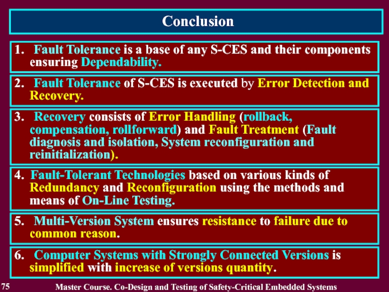
Fault Tolerance is the main mechanism, instrument ensuring Dependability
Master Course. Co-Design and Testing of Safety-Critical Embedded Systems
3.1.1. Motivation of Fault Tolerance Consideration
Reasons:
Fault Tolerance ensures operative resistance to hardware and software failures

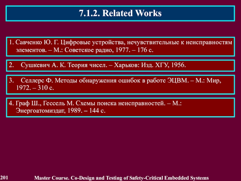
3. Lee P.A. and Anderson T., Fault Tolerance - Principles and Practice, second edition, Springer Verlag/Wien, 1990
2. Jean-Claude Laprie, Jean Arlat, Christian Beounes, Karama Kanoun and Catherine Hourtolle, Hardware and Software Fault Tolerance: Denition and Analysis of Architectural Solutions, in Proceedings FTCS 17, 1987

Effectiveness of Fault Tolerance: the effectiveness of error and fault handling mechanisms (their coverage) has a strong influence on Dependability Measures
Master Course. Co-Design and Testing of Safety-Critical Embedded Systems
Fault Tolerance:
Error Detection
Recovery

Error detection originates an error signal or message within the system. An error that is present but not detected is a latent error.
Master Course. Co-Design and Testing of Safety-Critical Embedded Systems
Fault Tolerance is generally implemented by error detection and subsequent system recovery.

Recovery consists of
Error Handling
Fault Handling (Fault treatment).
Master Course. Co-Design and Testing of Safety-Critical Embedded Systems

Master Course. Co-Design and Testing of Safety-Critical Embedded Systems

Fault Handling involves four steps:
• Fault Diagnosis: identifies and records the cause(s) of error(s), in terms of both location and type;
• Fault Isolation: performs physical or logical exclusion of the faulty components from further participation in service delivery, i.e., it makes the fault dormant;
• System Reconfiguration: either switches in spare components or reassigns tasks among non-failed components;
• System Reinitialization: checks, updates and records the new configuration and updates system tables and records.
Master Course. Co-Design and Testing of Safety-Critical Embedded Systems

Master Course. Co-Design and Testing of Safety-Critical Embedded Systems
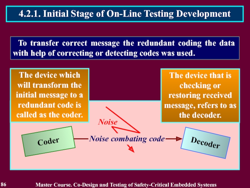
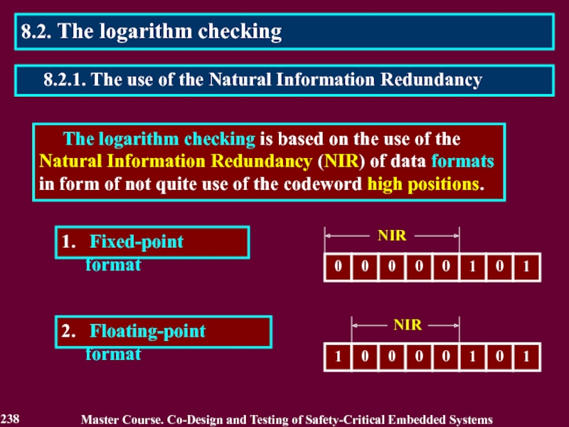
Fault-Tolerant Technologies based on various kinds of Redundancy and Reconfiguration.
Operative nature of the opposition to faults in safety-critical I&CS determines the important role of the methods and means of On-Line Testing in maintenance of Fault Tolerance.

Master Course. Co-Design and Testing of Safety-Critical Embedded Systems
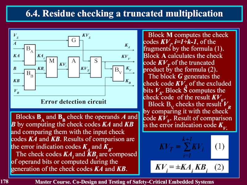
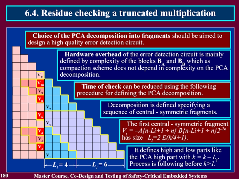
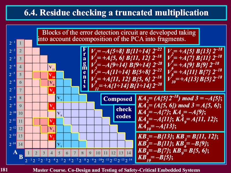
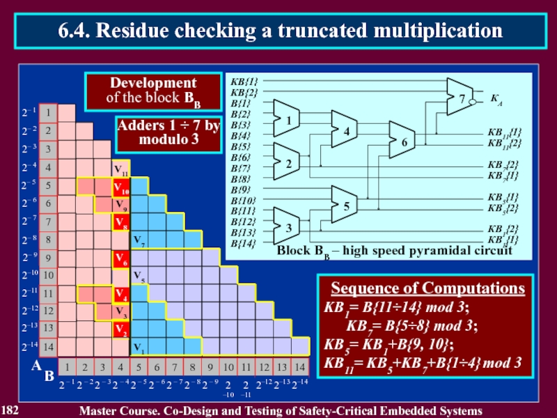
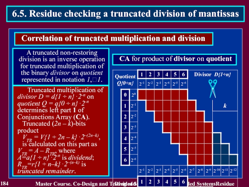
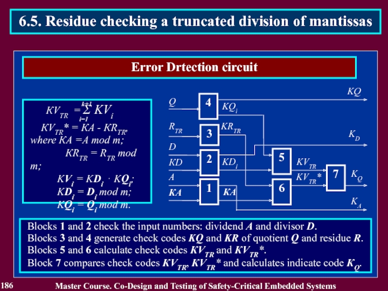
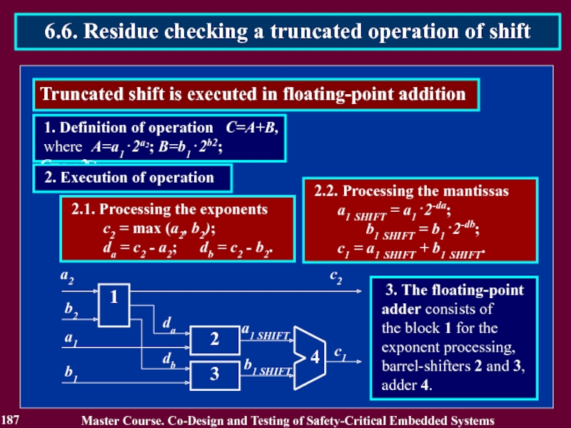
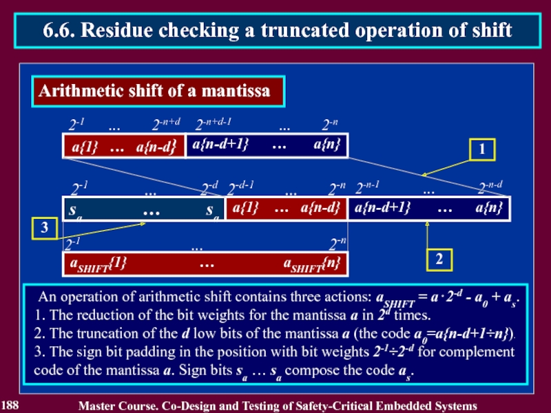
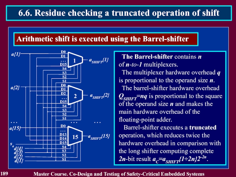
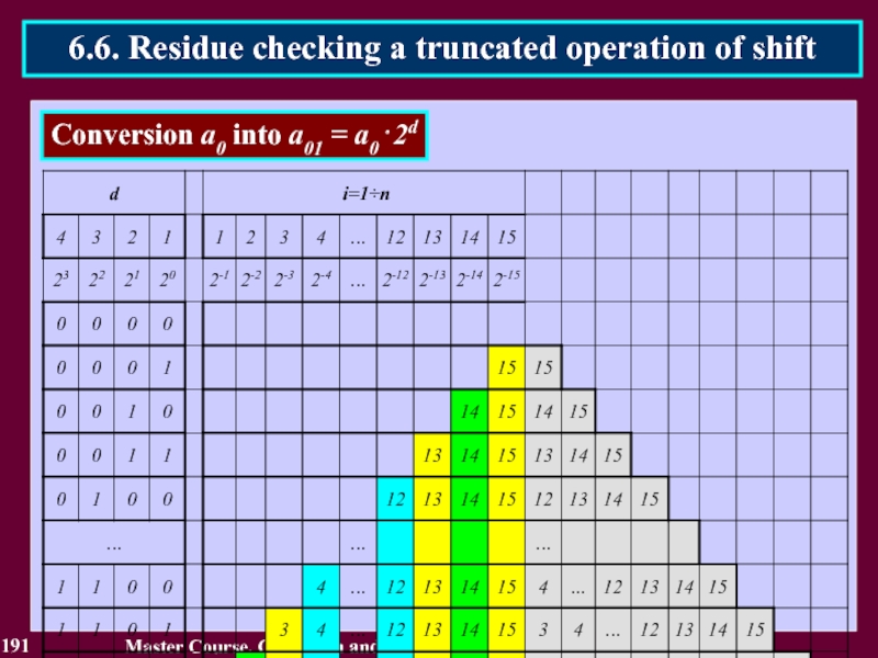
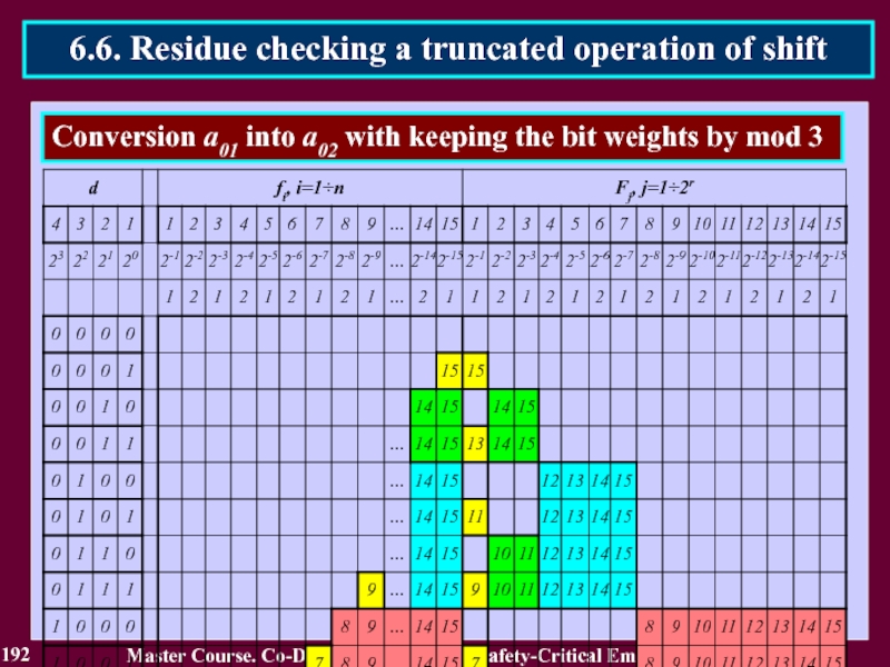
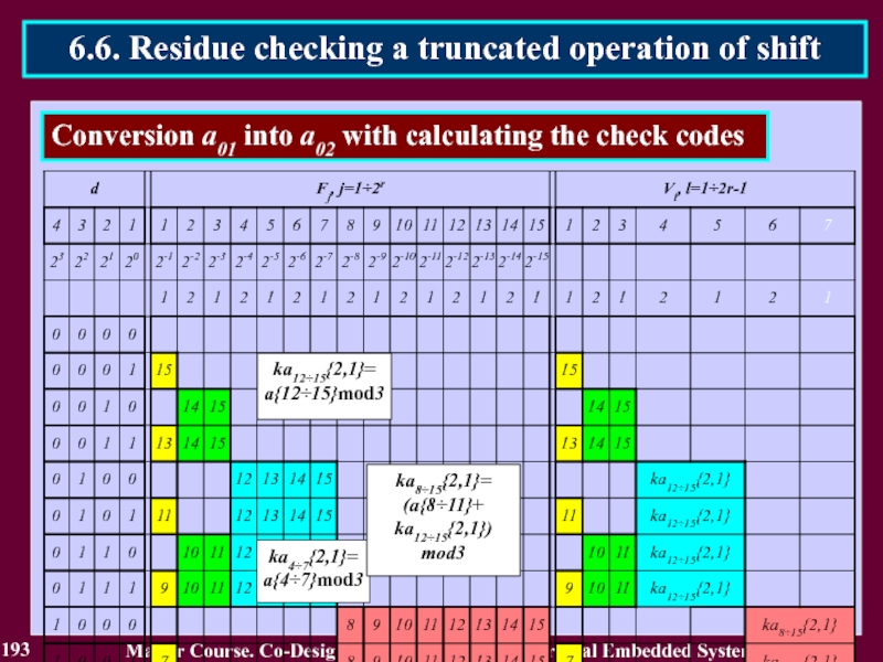
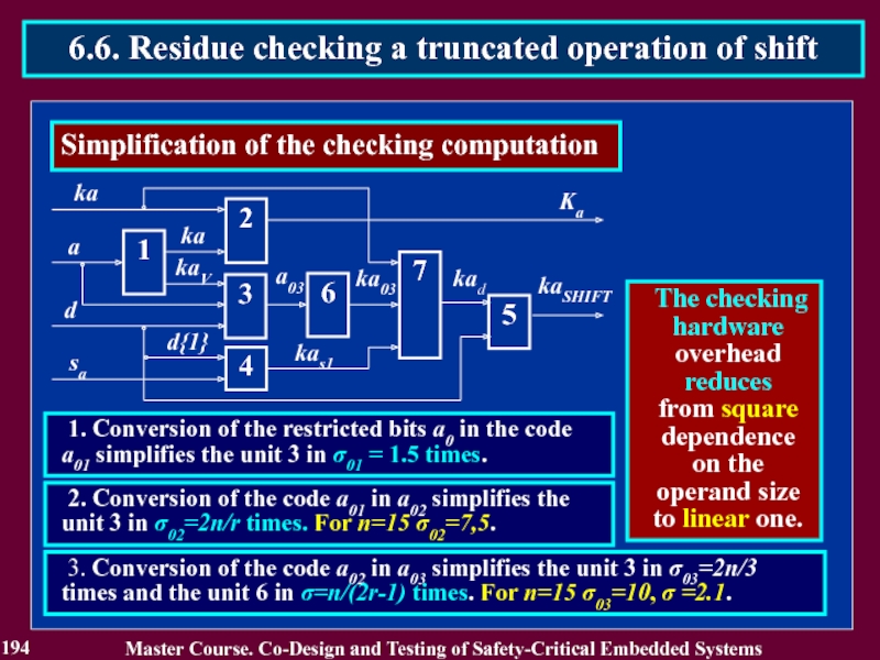
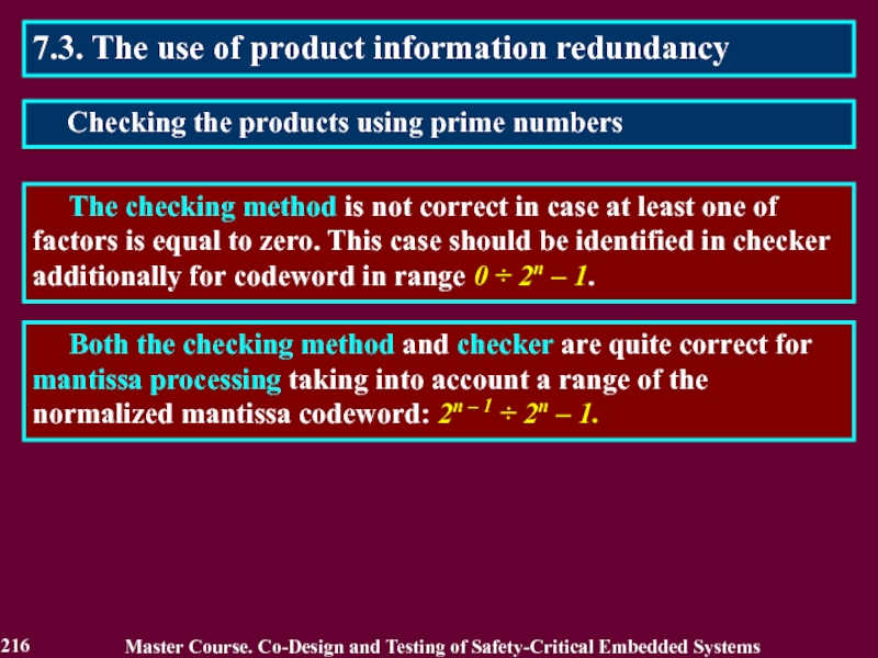
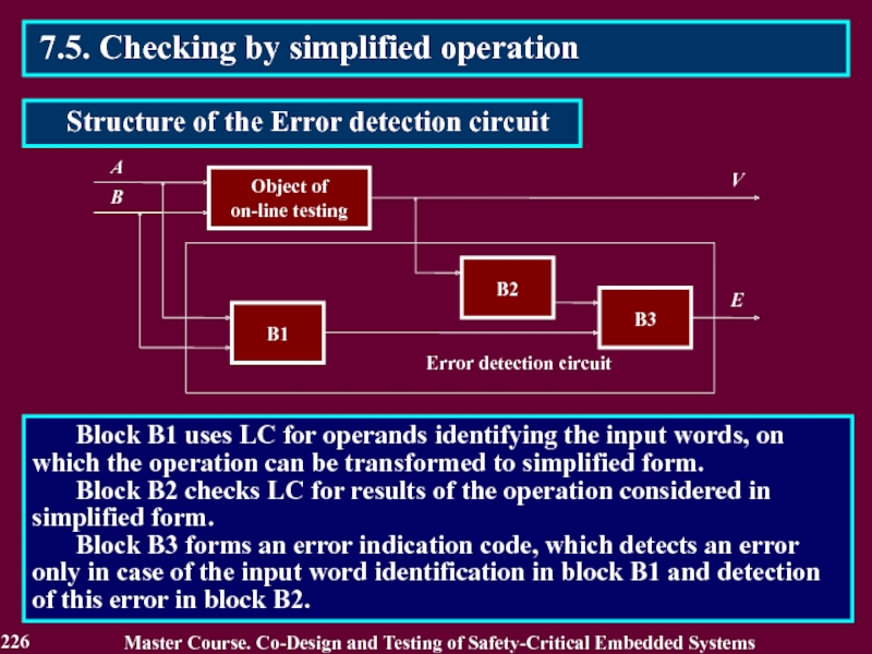
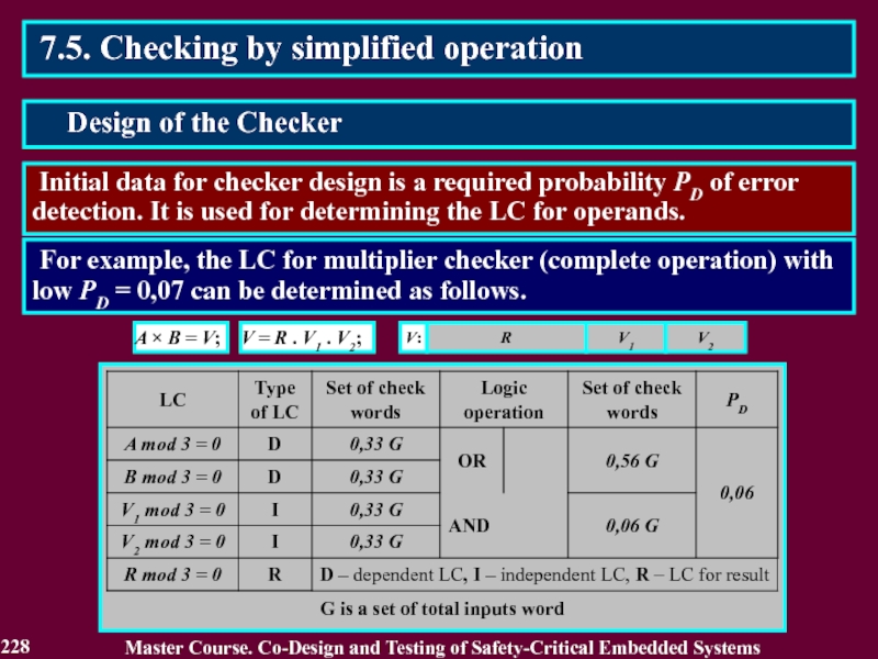
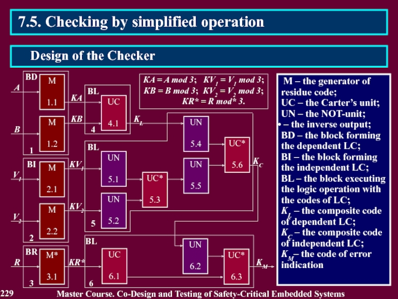
3.4.1.1. Residue Checking for Error Detection in arithmetic components

Master Course. Co-Design and Testing of Safety-Critical Embedded Systems
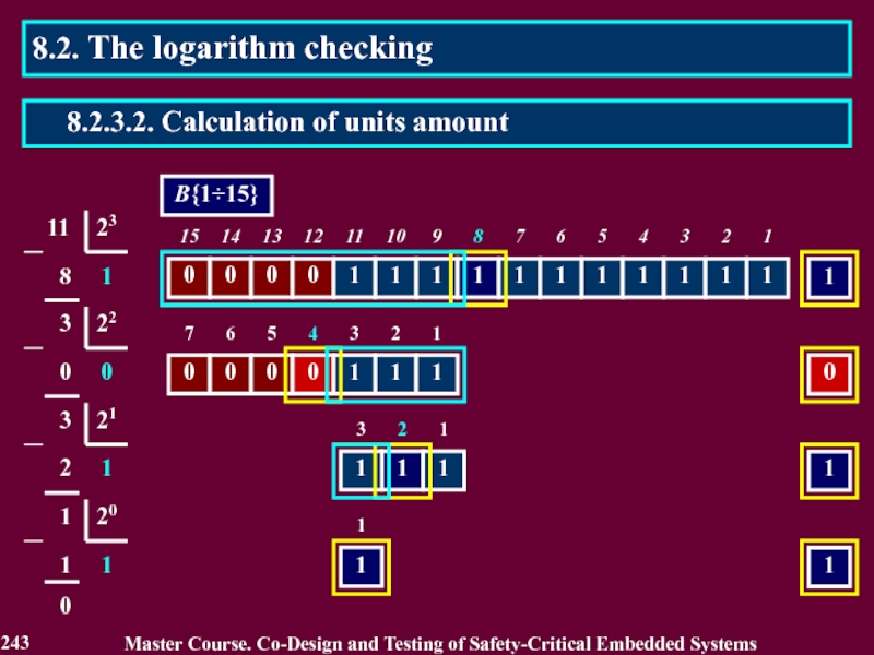
3.4.1.1. Residue Checking for Error Detection in arithmetic components

Master Course. Co-Design and Testing of Safety-Critical Embedded Systems
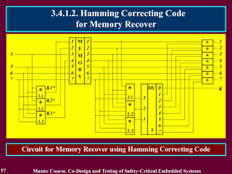
3.4.1.2. Hamming Correcting Code for Memory Recover
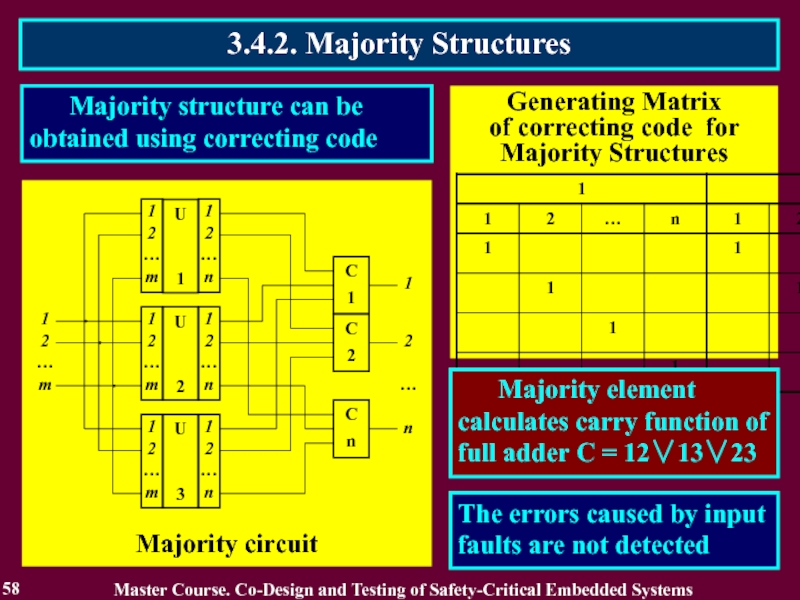
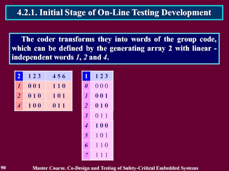
Generating Matrix of linear code

Если не удалось найти и скачать презентацию, Вы можете заказать его на нашем сайте. Мы постараемся найти нужный Вам материал и отправим по электронной почте. Не стесняйтесь обращаться к нам, если у вас возникли вопросы или пожелания:
Email: Нажмите что бы посмотреть
Это сайт презентаций, докладов, проектов, шаблонов в формате PowerPoint. Мы помогаем школьникам, студентам, учителям, преподавателям хранить и обмениваться учебными материалами с другими пользователями.