- Главная
- Разное
- Дизайн
- Бизнес и предпринимательство
- Аналитика
- Образование
- Развлечения
- Красота и здоровье
- Финансы
- Государство
- Путешествия
- Спорт
- Недвижимость
- Армия
- Графика
- Культурология
- Еда и кулинария
- Лингвистика
- Английский язык
- Астрономия
- Алгебра
- Биология
- География
- Детские презентации
- Информатика
- История
- Литература
- Маркетинг
- Математика
- Медицина
- Менеджмент
- Музыка
- МХК
- Немецкий язык
- ОБЖ
- Обществознание
- Окружающий мир
- Педагогика
- Русский язык
- Технология
- Физика
- Философия
- Химия
- Шаблоны, картинки для презентаций
- Экология
- Экономика
- Юриспруденция
Addressing the Network - IPV4. Part I презентация
Содержание
- 1. Addressing the Network - IPV4. Part I
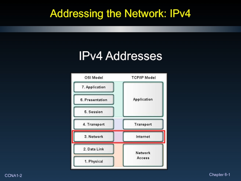
- 2. Addressing the Network: IPv4 IPv4 Addresses
- 3. Anatomy of an IPv4 Address Each device
- 4. Anatomy of an IPv4 Address Devices use
- 5. Anatomy of an IPv4 Address To identify
- 6. Anatomy of an IPv4 Address Network Portion:
- 7. Anatomy of an IPv4 Address Host Portion:
- 8. Binary to Decimal Conversion In all number
- 9. Binary to Decimal Conversion Positional Notation (Decimal
- 10. Binary to Decimal Conversion Computers react only
- 11. Binary to Decimal Conversion Positional Notation (Binary
- 12. Binary to Decimal Conversion
- 13. Binary to Decimal Conversion IP Address:
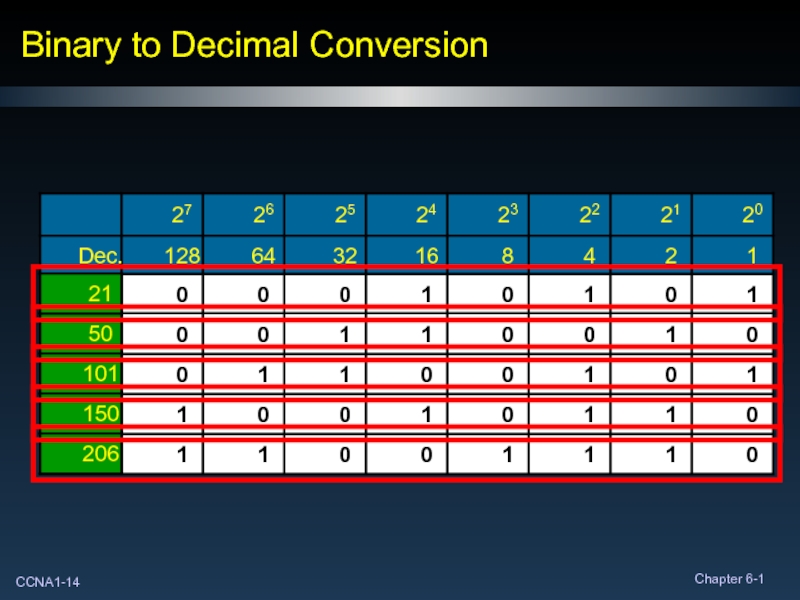
- 14. Binary to Decimal Conversion
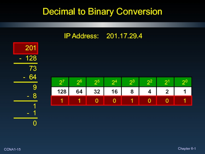
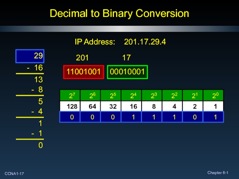
- 15. Decimal to Binary Conversion IP Address: 201.17.29.4 201 1 0 0 1 1
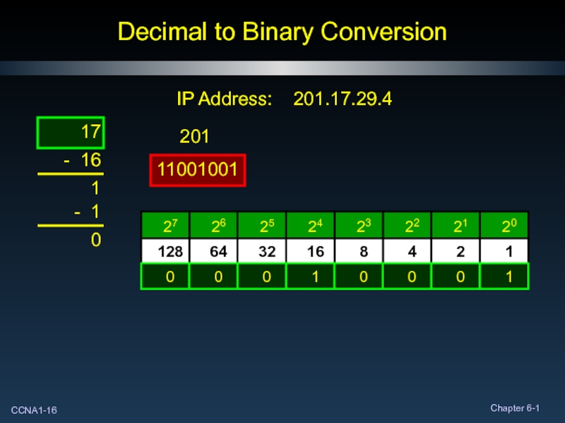
- 16. Decimal to Binary Conversion IP Address: 201.17.29.4 17
- 17. Decimal to Binary Conversion IP Address: 201.17.29.4 29 1 1
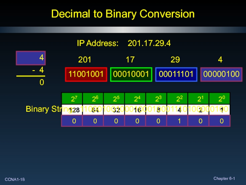
- 18. Decimal to Binary Conversion IP Address: 201.17.29.4 4 Binary String: 110001001000100010001110100000100
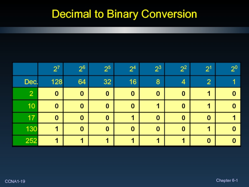
- 19. Decimal to Binary Conversion
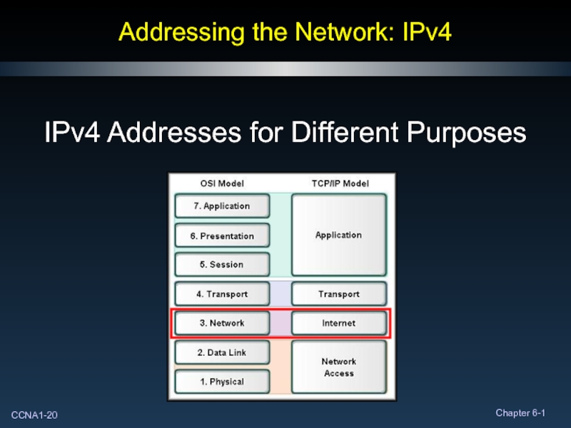
- 20. Addressing the Network: IPv4 IPv4 Addresses for Different Purposes
- 21. Types of Addresses in an IPv4 Network
- 22. Network Address Standard way to reference a
- 23. Broadcast Address The destination address of a
- 24. Host Address The unique address assigned to
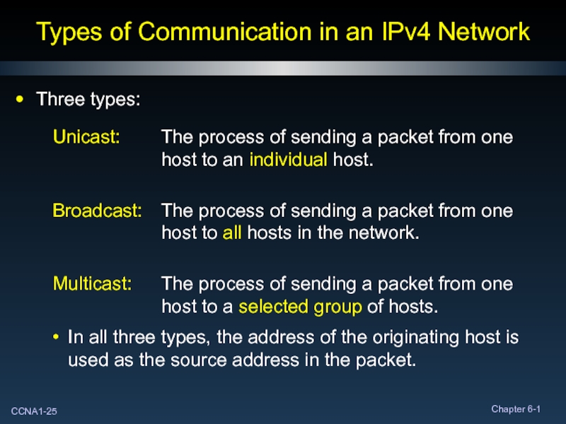
- 25. Types of Communication in an IPv4 Network
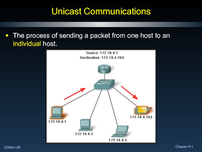
- 26. Unicast Communications The process of sending a packet from one host to an individual host.
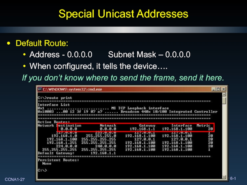
- 27. Special Unicast Addresses Default Route: Address -
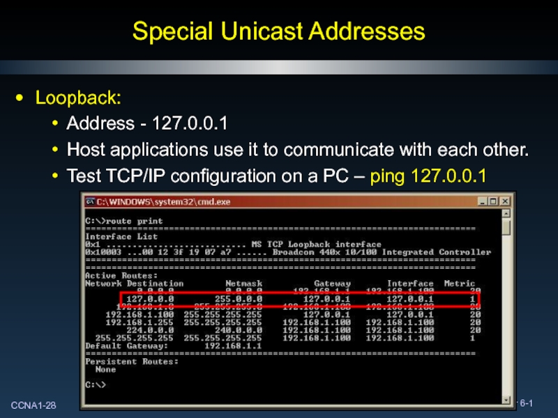
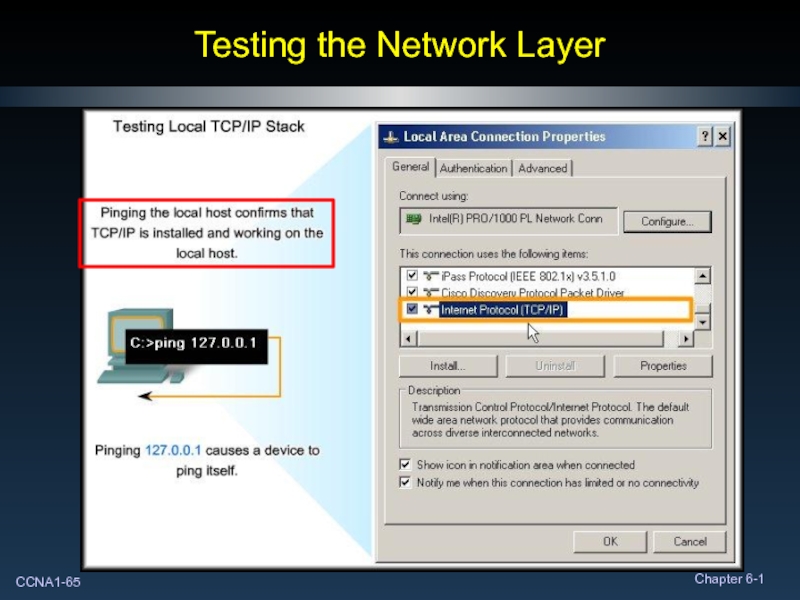
- 28. Special Unicast Addresses Loopback: Address - 127.0.0.1
- 29. Special Unicast Addresses Link Local Addresses: Address
- 30. Special Unicast Addresses Test-Net Addresses: Address Range
- 31. Special Unicast Addresses Experimental Address Range: Address
- 32. Special Unicast Addresses Public and Private Addresses:
- 33. Broadcast Communications The process of sending a
- 34. Broadcast Communications Broadcasts are not forwarded by
- 35. Multicast Communications The process of sending a
- 36. Multicast Communications Multicasting involves the use of
- 37. Multicast Communications The reserved multicast network or
- 38. Reserved and Special Purpose Addresses
- 39. Addressing the Network: IPv4 IANA and ISPs
- 40. Internet Assigned Numbers Authority (IANA) To have
- 41. Internet Service Provider (ISP) Most companies or
- 42. Internet Service Provider (ISP) ISPs are designated
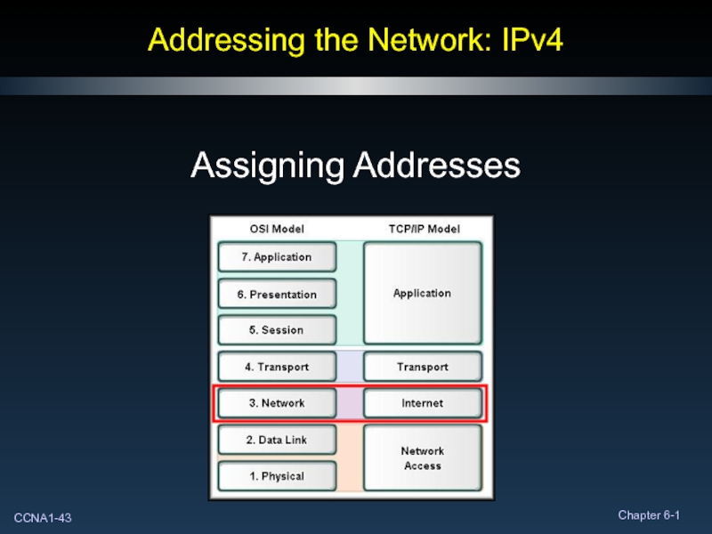
- 43. Addressing the Network: IPv4 Assigning Addresses
- 44. Planning to Address the Network Planning and
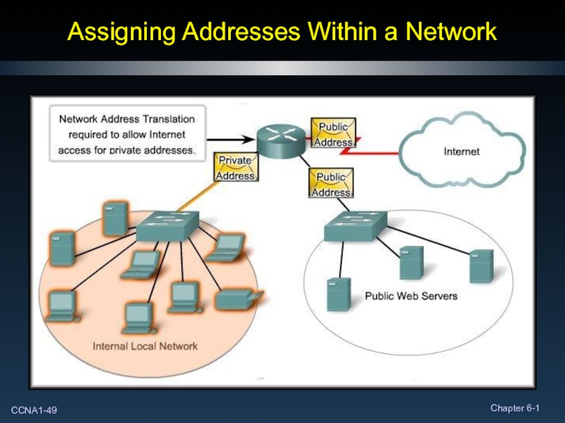
- 45. Assigning Addresses Within a Network The IP
- 46. Assigning Addresses Within a Network Considerations –
- 47. Assigning Addresses Within a Network
- 48. Assigning Addresses Within a Network
- 49. Assigning Addresses Within a Network
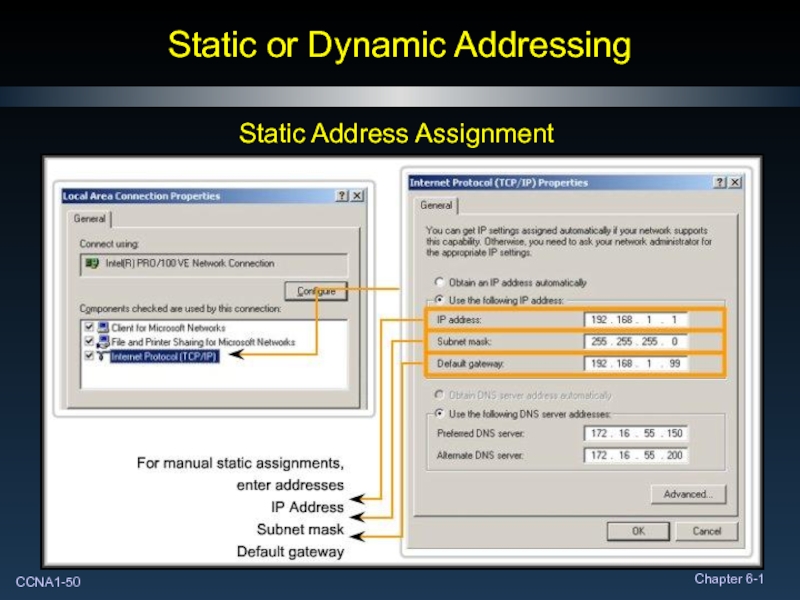
- 50. Static or Dynamic Addressing Static Address Assignment
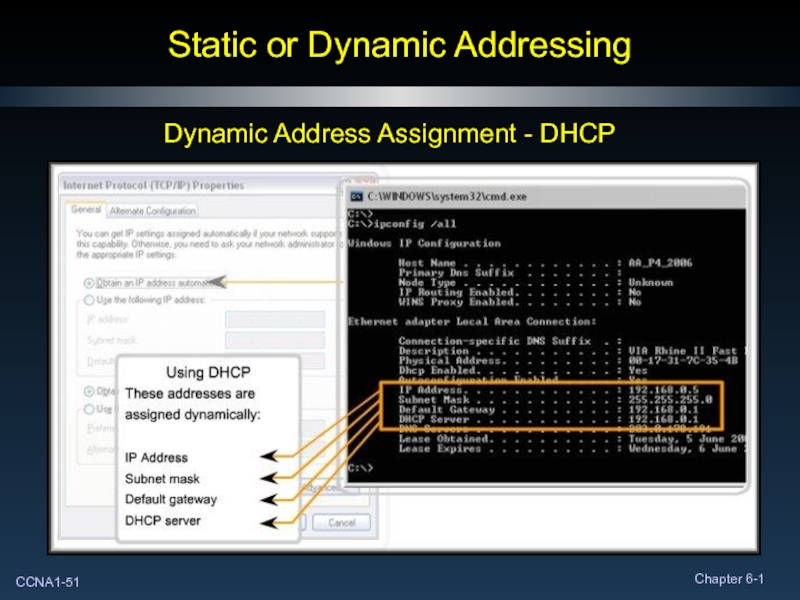
- 51. Static or Dynamic Addressing Dynamic Address Assignment - DHCP
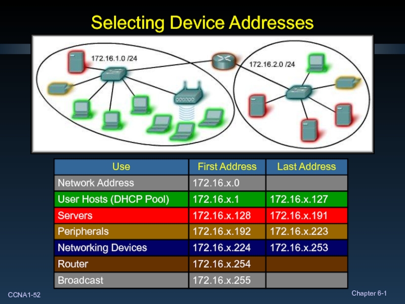
- 52. Selecting Device Addresses
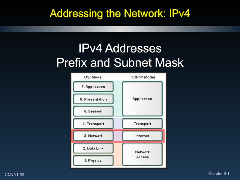
- 53. Addressing the Network: IPv4 IPv4 Addresses Prefix and Subnet Mask
- 54. Network Prefixes How do you know the
- 55. Network Prefixes Networks are not always assigned
- 56. Subnet Mask How do the network devices
- 57. Subnet Mask There is a direct, one-to-one
- 58. Subnet Mask
- 59. Subnet Mask IP Address: 10.24.36.2 / 8
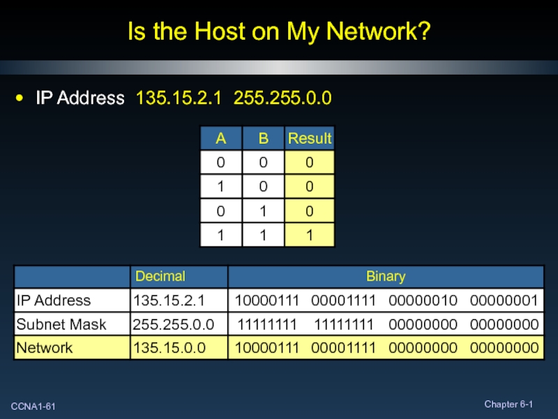
- 60. Is the Host on My Network? To
- 61. Is the Host on My Network? IP Address 135.15.2.1 255.255.0.0
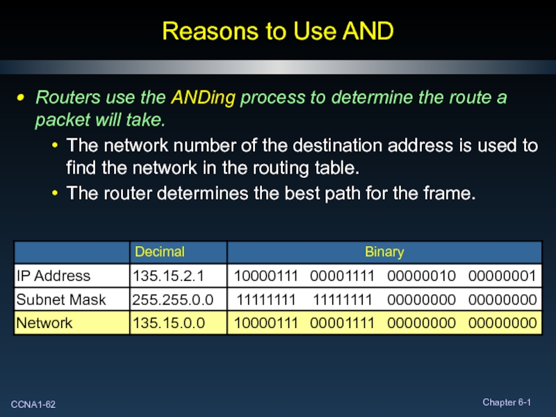
- 62. Reasons to Use AND Routers use the
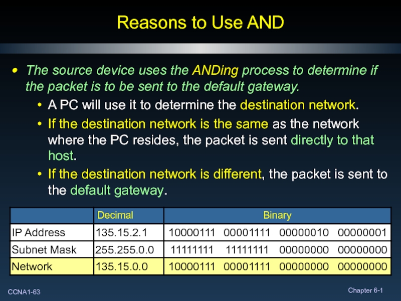
- 63. Reasons to Use AND The source device
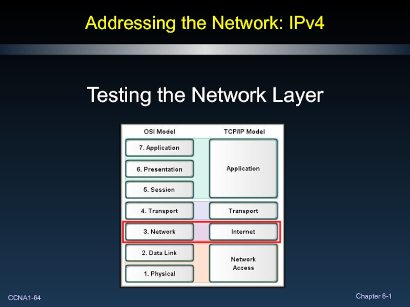
- 64. Addressing the Network: IPv4 Testing the Network Layer
- 65. Testing the Network Layer
- 66. Testing the Network Layer
- 67. Testing the Network Layer C:>ping 10.0.1.2
- 68. Testing the Network Layer
- 69. Testing the Network Layer ICMPv4: Protocol for
- 70. There’s that truck again……. Your turn to do stuff!
Слайд 3Anatomy of an IPv4 Address
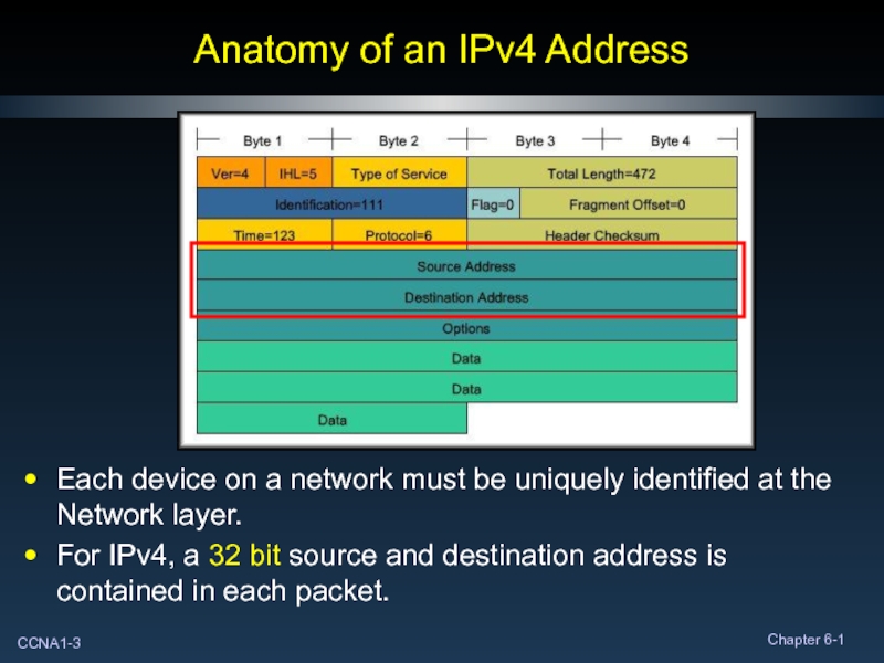
Each device on a network must be
For IPv4, a 32 bit source and destination address is contained in each packet.
Слайд 4Anatomy of an IPv4 Address
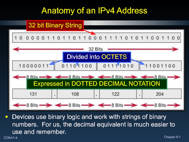
Devices use binary logic and work with
Expressed in DOTTED DECIMAL NOTATION
Слайд 5Anatomy of an IPv4 Address
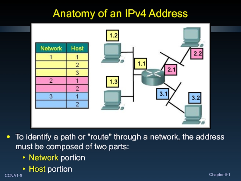
To identify a path or "route" through
Network portion
Host portion
1.1
1.2
1.3
2.1
2.2
3.1
3.2
Слайд 6Anatomy of an IPv4 Address
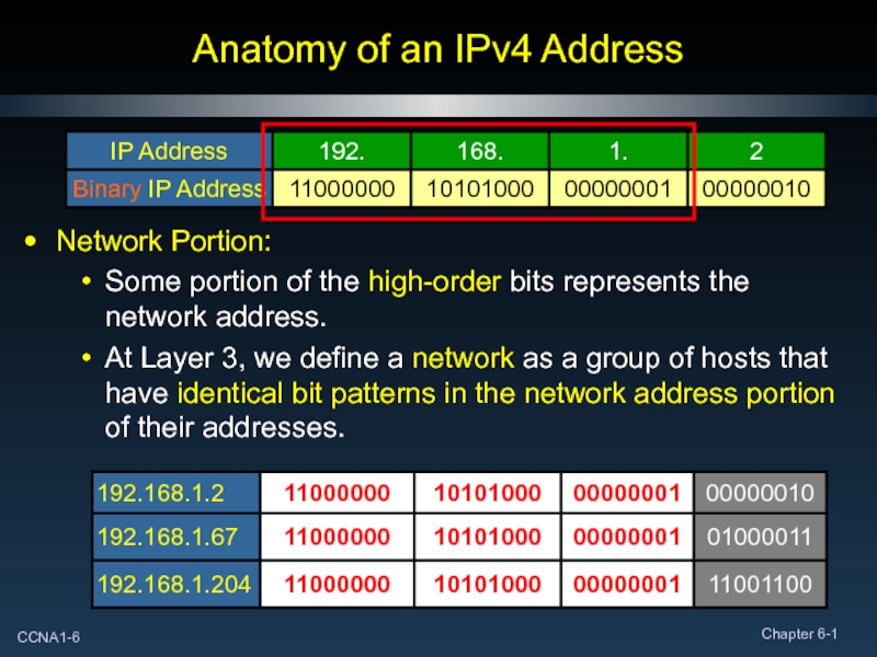
Network Portion:
Some portion of the high-order bits
At Layer 3, we define a network as a group of hosts that have identical bit patterns in the network address portion of their addresses.
Слайд 7Anatomy of an IPv4 Address
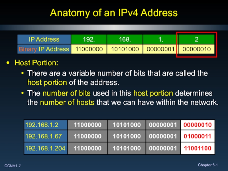
Host Portion:
There are a variable number of
The number of bits used in this host portion determines the number of hosts that we can have within the network.
Слайд 8Binary to Decimal Conversion
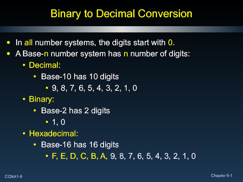
In all number systems, the digits start with
A Base-n number system has n number of digits:
Decimal:
Base-10 has 10 digits
9, 8, 7, 6, 5, 4, 3, 2, 1, 0
Binary:
Base-2 has 2 digits
1, 0
Hexadecimal:
Base-16 has 16 digits
F, E, D, C, B, A, 9, 8, 7, 6, 5, 4, 3, 2, 1, 0
Слайд 9Binary to Decimal Conversion
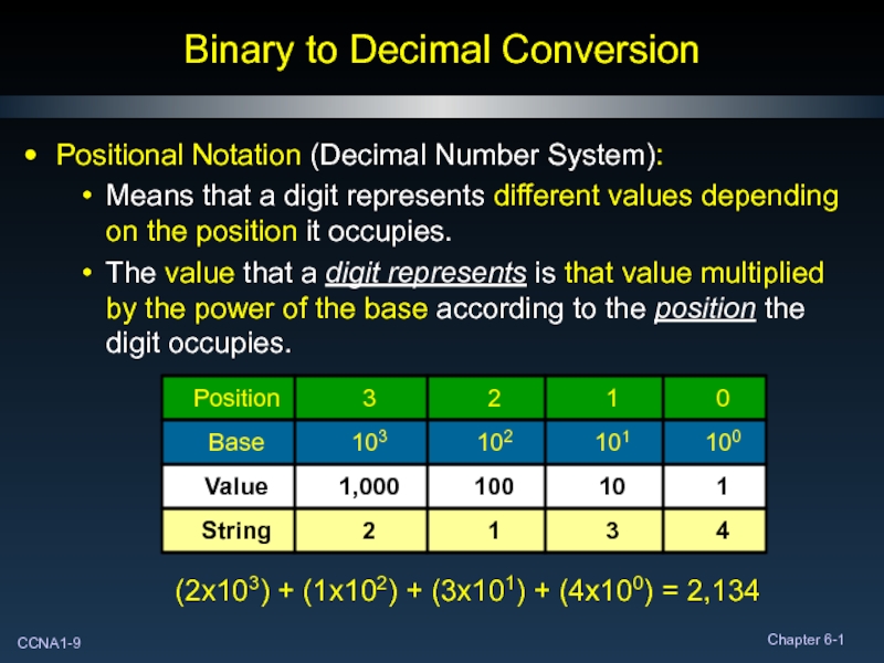
Positional Notation (Decimal Number System):
Means that a digit
The value that a digit represents is that value multiplied by the power of the base according to the position the digit occupies.
(2x10³) + (1x10²) + (3x101) + (4x100) = 2,134
Слайд 10Binary to Decimal Conversion
Computers react only to electrical impulses.
They work with
They can only understand and use data that is in this two state format.
These 1's and 0's are called binary digits or bits.
Слайд 11Binary to Decimal Conversion
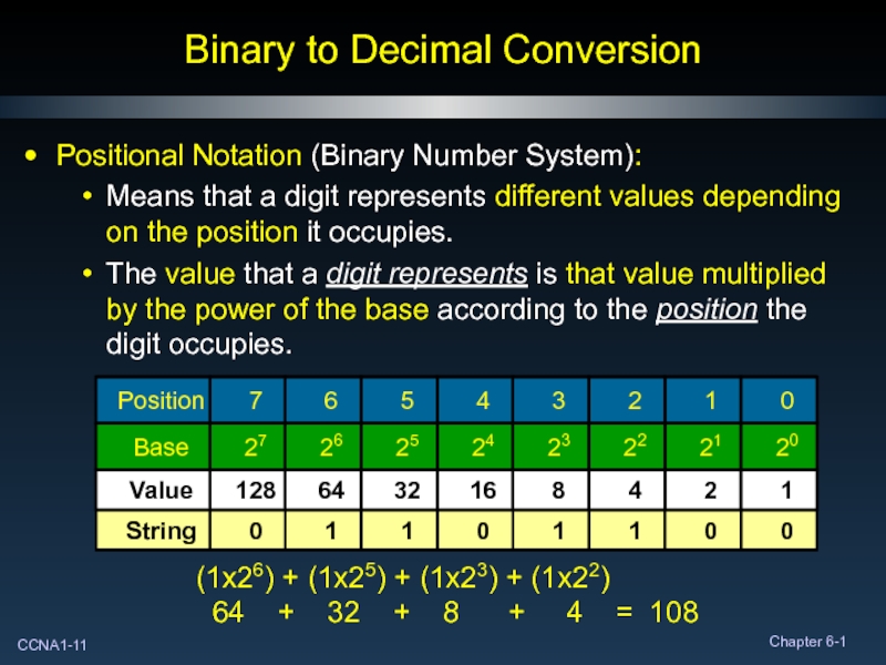
Positional Notation (Binary Number System):
Means that a digit
The value that a digit represents is that value multiplied by the power of the base according to the position the digit occupies.
(1x26) + (1x25) + (1x23) + (1x22)
64 + 32 + 8 + 4 = 108
Слайд 13Binary to Decimal Conversion
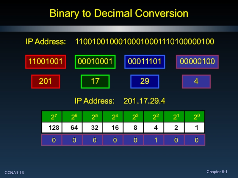
IP Address: 11001001000100010001110100000100
11001001
00010001
00000100
00011101
201
17
29
4
IP Address: 201.17.29.4
Слайд 18Decimal to Binary Conversion
IP Address: 201.17.29.4
4
Binary String: 110001001000100010001110100000100
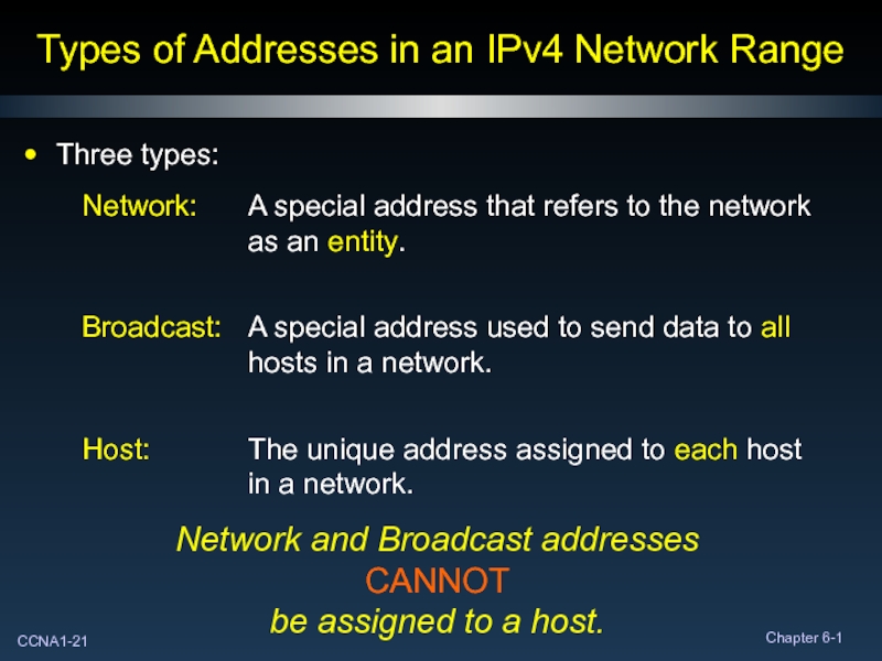
Слайд 21Types of Addresses in an IPv4 Network Range
Three types:
Network and Broadcast
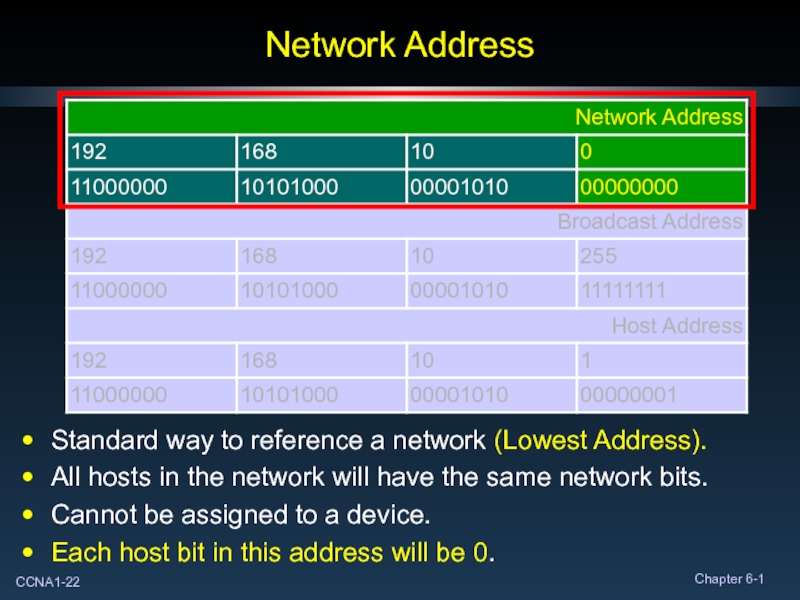
Слайд 22Network Address
Standard way to reference a network (Lowest Address).
All hosts in
Cannot be assigned to a device.
Each host bit in this address will be 0.
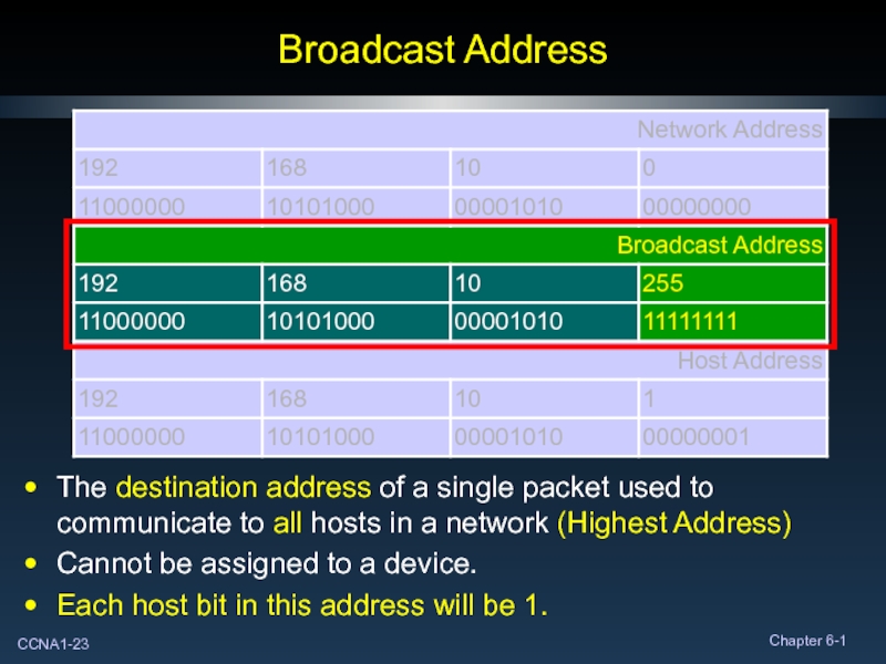
Слайд 23Broadcast Address
The destination address of a single packet used to communicate
Cannot be assigned to a device.
Each host bit in this address will be 1.
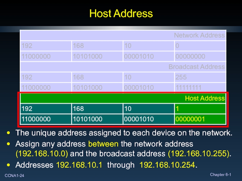
Слайд 24Host Address
The unique address assigned to each device on the network.
Assign
Addresses 192.168.10.1 through 192.168.10.254.
Слайд 25Types of Communication in an IPv4 Network
Three types:
In all three
Слайд 27Special Unicast Addresses
Default Route:
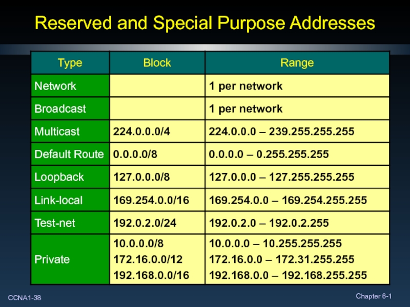
Address - 0.0.0.0 Subnet Mask
When configured, it tells the device….
If you don’t know where to send the frame, send it here.
Слайд 28Special Unicast Addresses
Loopback:
Address - 127.0.0.1
Host applications use it to communicate with
Test TCP/IP configuration on a PC – ping 127.0.0.1
Слайд 29Special Unicast Addresses
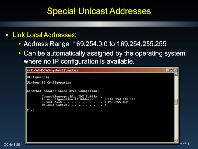
Link Local Addresses:
Address Range 169.254.0.0 to 169.254.255.255
Can be automatically
Слайд 30Special Unicast Addresses
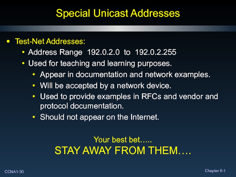
Test-Net Addresses:
Address Range 192.0.2.0 to 192.0.2.255
Used for teaching and
Appear in documentation and network examples.
Will be accepted by a network device.
Used to provide examples in RFCs and vendor and protocol documentation.
Should not appear on the Internet.
Your best bet…..
STAY AWAY FROM THEM….
Слайд 31Special Unicast Addresses
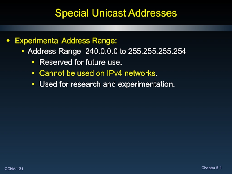
Experimental Address Range:
Address Range 240.0.0.0 to 255.255.255.254
Reserved for future
Cannot be used on IPv4 networks.
Used for research and experimentation.
Слайд 32Special Unicast Addresses
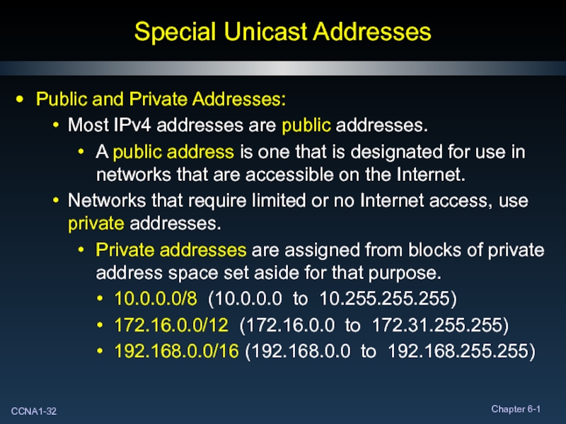
Public and Private Addresses:
Most IPv4 addresses are public addresses.
A
Networks that require limited or no Internet access, use private addresses.
Private addresses are assigned from blocks of private address space set aside for that purpose.
10.0.0.0/8 (10.0.0.0 to 10.255.255.255)
172.16.0.0/12 (172.16.0.0 to 172.31.255.255)
192.168.0.0/16 (192.168.0.0 to 192.168.255.255)
Слайд 33Broadcast Communications
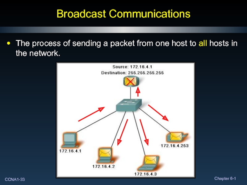
The process of sending a packet from one host to
Слайд 34Broadcast Communications
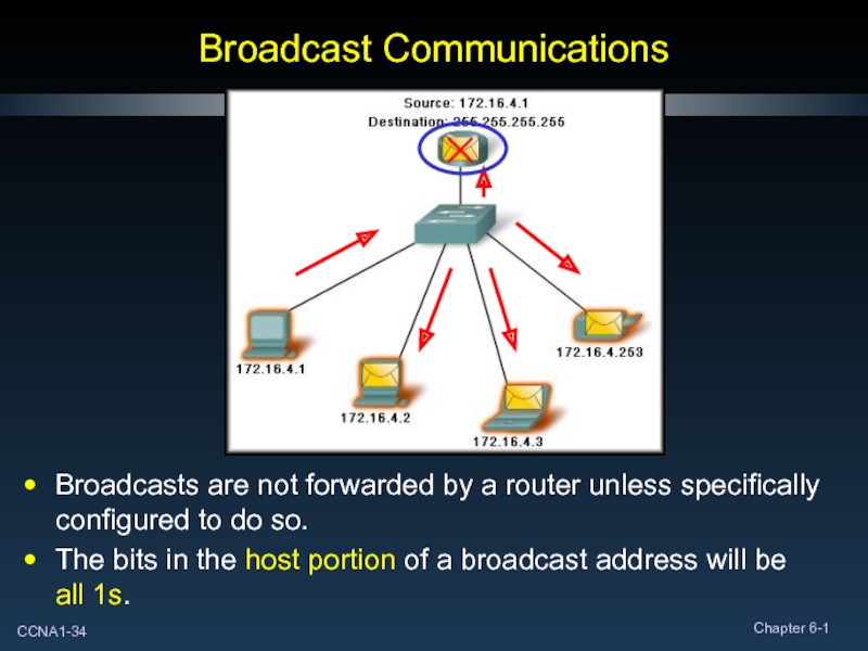
Broadcasts are not forwarded by a router unless specifically
configured to
The bits in the host portion of a broadcast address will be all 1s.
Слайд 35Multicast Communications
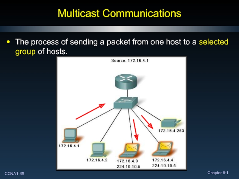
The process of sending a packet from one host to
Слайд 36Multicast Communications
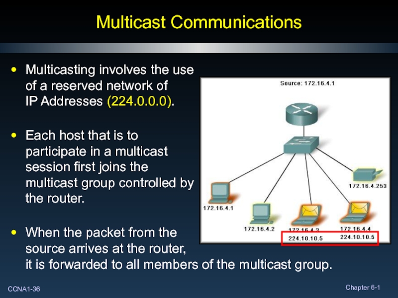
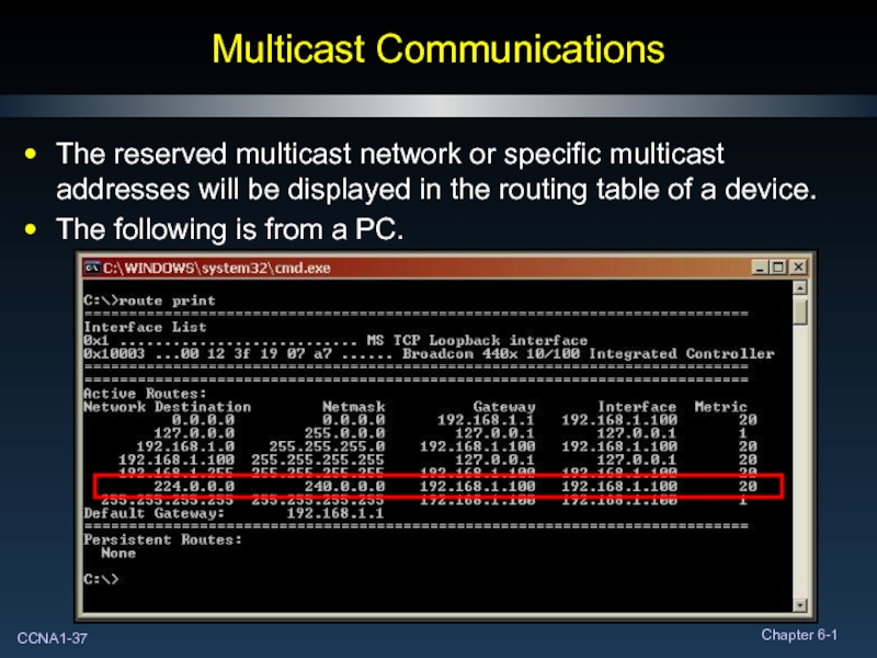
Multicasting involves the use
of a reserved network of
IP Addresses (224.0.0.0).
Each
When the packet from the source arrives at the router, it is forwarded to all members of the multicast group.
Слайд 37Multicast Communications
The reserved multicast network or specific multicast addresses will be
The following is from a PC.
Слайд 40Internet Assigned Numbers Authority (IANA)
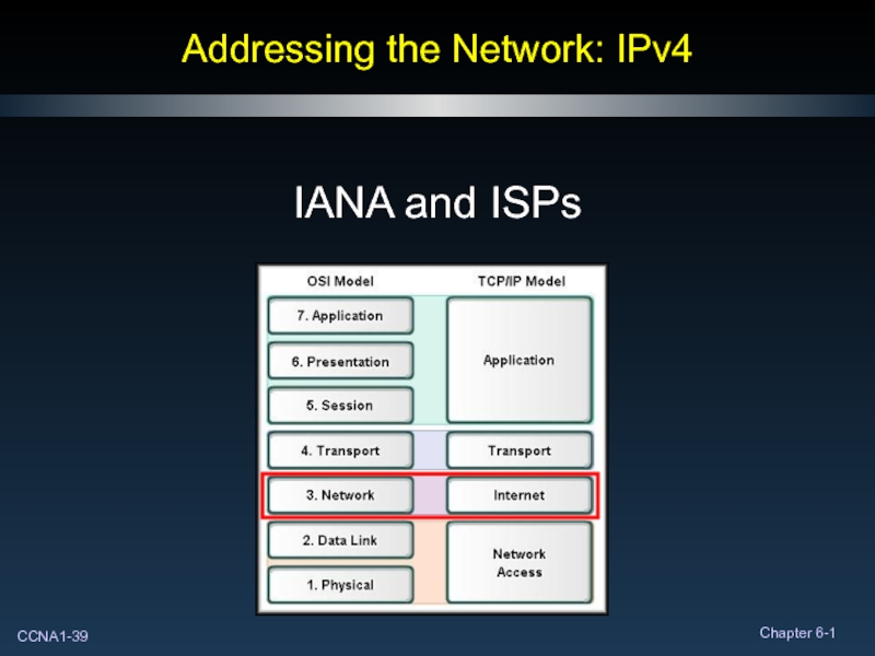
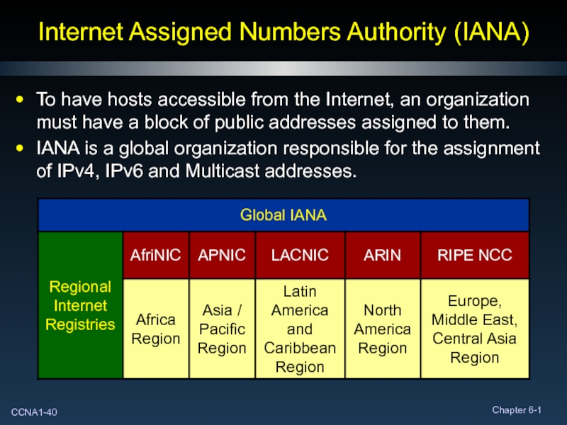
To have hosts accessible from the Internet,
IANA is a global organization responsible for the assignment of IPv4, IPv6 and Multicast addresses.
Слайд 41Internet Service Provider (ISP)
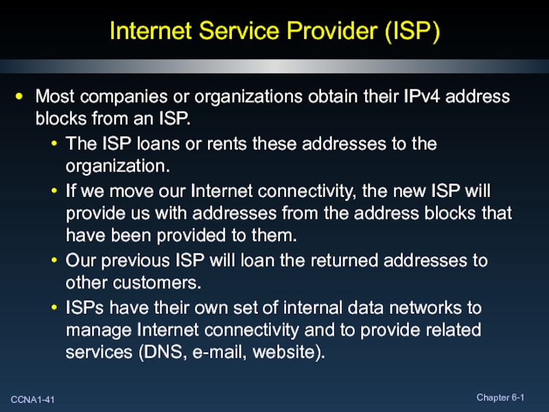
Most companies or organizations obtain their IPv4 address
The ISP loans or rents these addresses to the organization.
If we move our Internet connectivity, the new ISP will provide us with addresses from the address blocks that have been provided to them.
Our previous ISP will loan the returned addresses to other customers.
ISPs have their own set of internal data networks to manage Internet connectivity and to provide related services (DNS, e-mail, website).
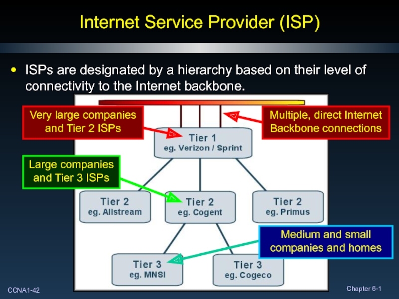
Слайд 42Internet Service Provider (ISP)
ISPs are designated by a hierarchy based on
Слайд 44Planning to Address the Network
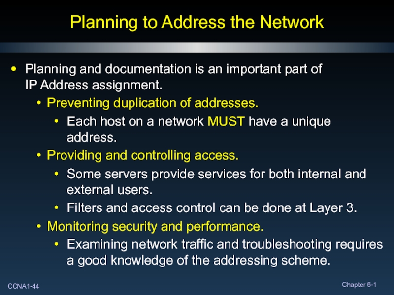
Planning and documentation is an important part
Preventing duplication of addresses.
Each host on a network MUST have a unique address.
Providing and controlling access.
Some servers provide services for both internal and external users.
Filters and access control can be done at Layer 3.
Monitoring security and performance.
Examining network traffic and troubleshooting requires a good knowledge of the addressing scheme.
Слайд 45Assigning Addresses Within a Network
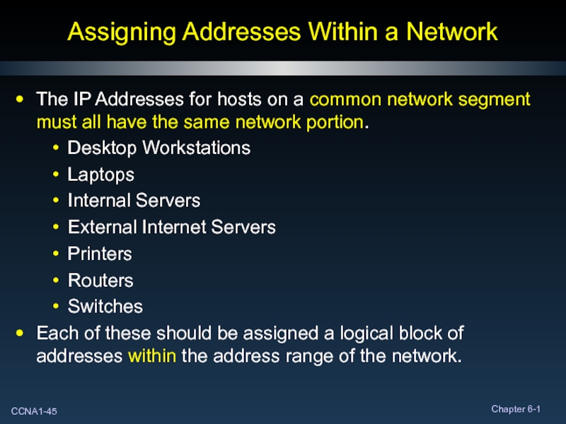
The IP Addresses for hosts on a
Desktop Workstations
Laptops
Internal Servers
External Internet Servers
Printers
Routers
Switches
Each of these should be assigned a logical block of addresses within the address range of the network.
Слайд 46Assigning Addresses Within a Network
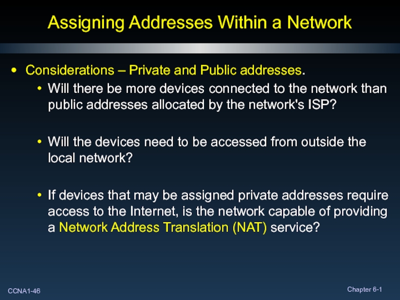
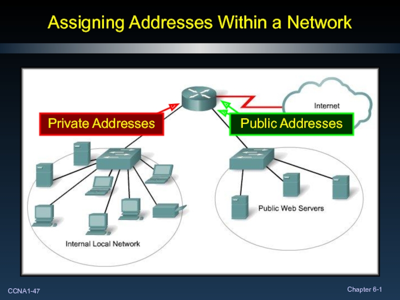
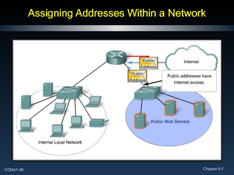
Considerations – Private and Public addresses.
Will there
Will the devices need to be accessed from outside the local network?
If devices that may be assigned private addresses require access to the Internet, is the network capable of providing a Network Address Translation (NAT) service?
Слайд 54Network Prefixes
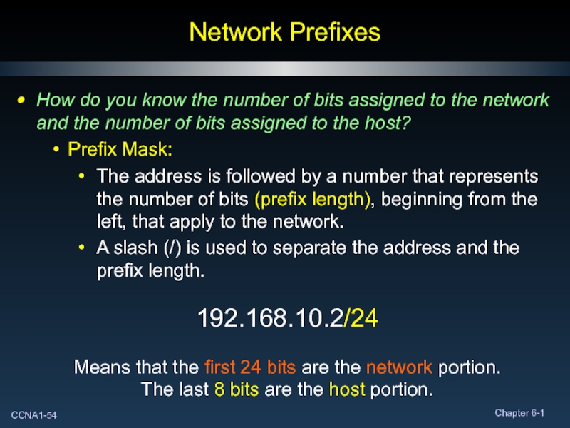
How do you know the number of bits assigned to
Prefix Mask:
The address is followed by a number that represents the number of bits (prefix length), beginning from the left, that apply to the network.
A slash (/) is used to separate the address and the prefix length.
192.168.10.2/24
Means that the first 24 bits are the network portion.
The last 8 bits are the host portion.
Слайд 55Network Prefixes
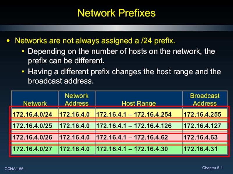
Networks are not always assigned a /24 prefix.
Depending on the
Having a different prefix changes the host range and the broadcast address.
Слайд 56Subnet Mask
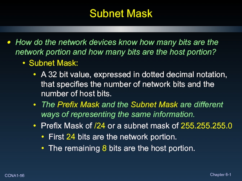
How do the network devices know how many bits are
Subnet Mask:
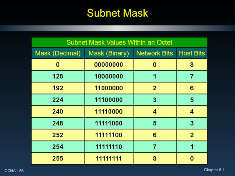
A 32 bit value, expressed in dotted decimal notation, that specifies the number of network bits and the number of host bits.
The Prefix Mask and the Subnet Mask are different ways of representing the same information.
Prefix Mask of /24 or a subnet mask of 255.255.255.0
First 24 bits are the network portion.
The remaining 8 bits are the host portion.
Слайд 57Subnet Mask
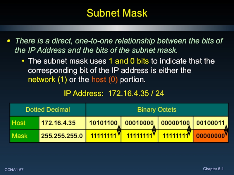
There is a direct, one-to-one relationship between the bits of
The subnet mask uses 1 and 0 bits to indicate that the corresponding bit of the IP address is either the network (1) or the host (0) portion.
IP Address: 172.16.4.35 / 24
Слайд 59Subnet Mask
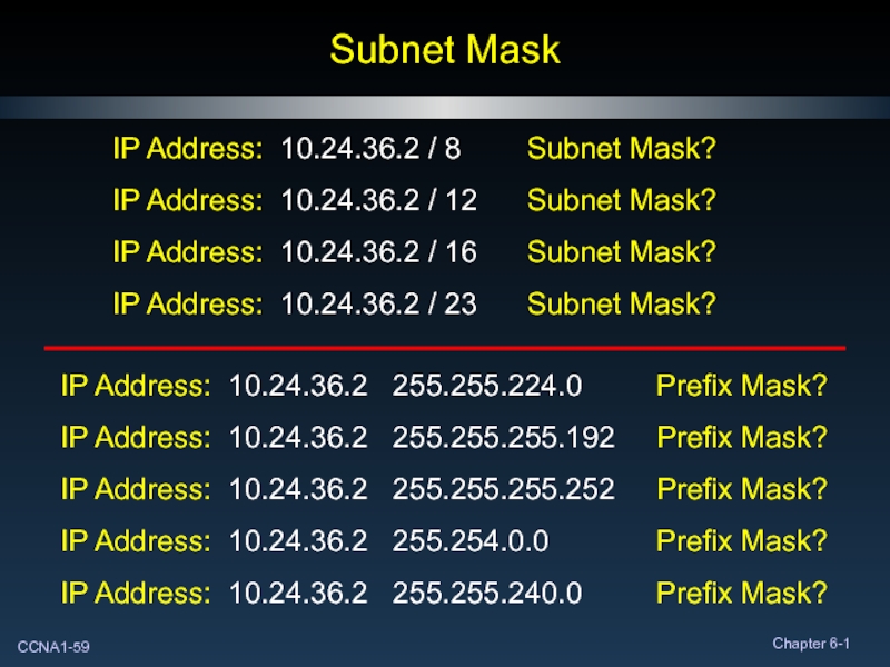
IP Address: 10.24.36.2 / 8 Subnet Mask?
IP
IP Address: 10.24.36.2 / 16 Subnet Mask?
IP Address: 10.24.36.2 / 23 Subnet Mask?
IP Address: 10.24.36.2 255.255.224.0 Prefix Mask?
IP Address: 10.24.36.2 255.255.255.192 Prefix Mask?
IP Address: 10.24.36.2 255.255.255.252 Prefix Mask?
IP Address: 10.24.36.2 255.254.0.0 Prefix Mask?
IP Address: 10.24.36.2 255.255.240.0 Prefix Mask?
Слайд 60Is the Host on My Network?
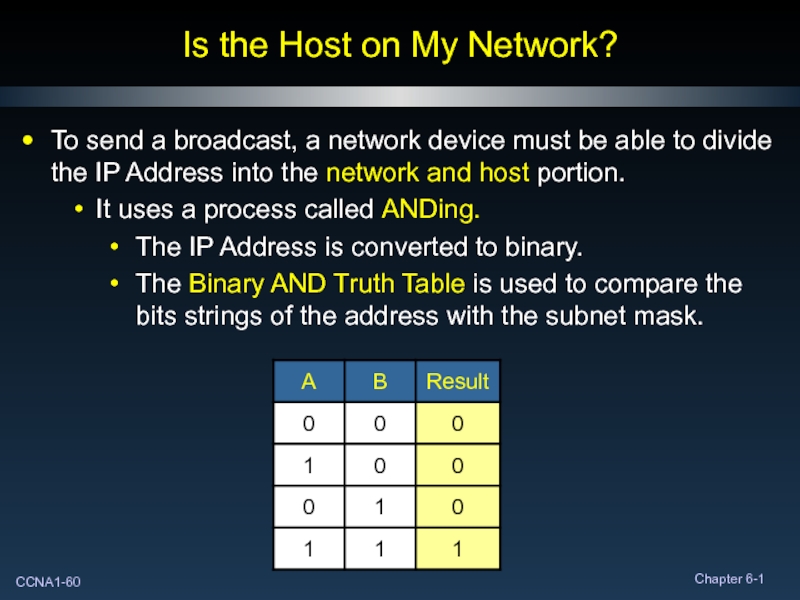
To send a broadcast, a network
It uses a process called ANDing.
The IP Address is converted to binary.
The Binary AND Truth Table is used to compare the bits strings of the address with the subnet mask.
Слайд 62Reasons to Use AND
Routers use the ANDing process to determine the
The network number of the destination address is used to find the network in the routing table.
The router determines the best path for the frame.
Слайд 63Reasons to Use AND
The source device uses the ANDing process to
A PC will use it to determine the destination network.
If the destination network is the same as the network where the PC resides, the packet is sent directly to that host.
If the destination network is different, the packet is sent to the default gateway.
Слайд 69Testing the Network Layer
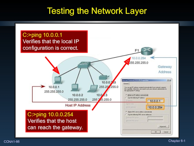
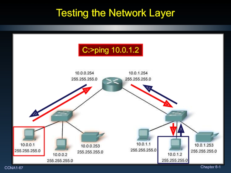
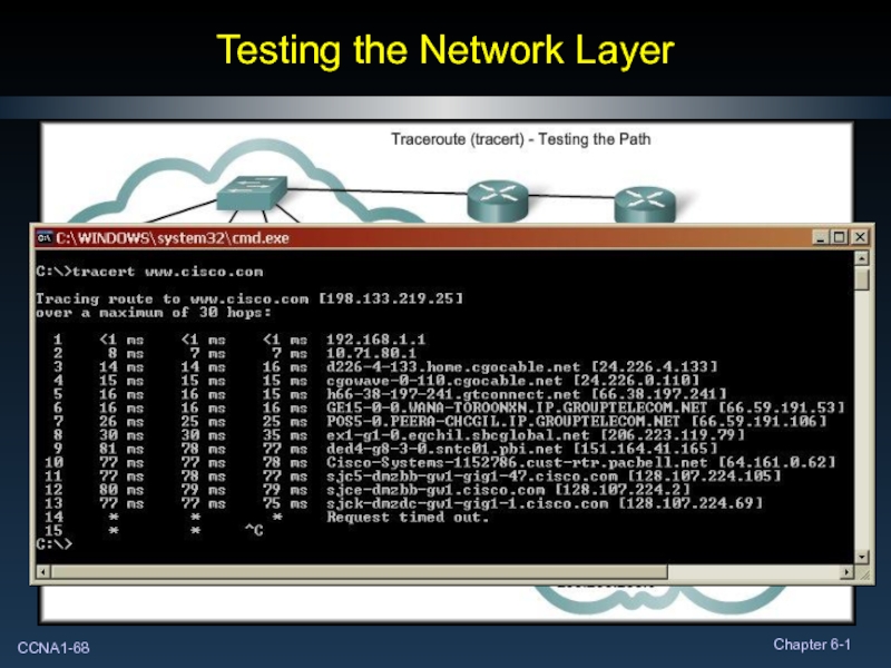
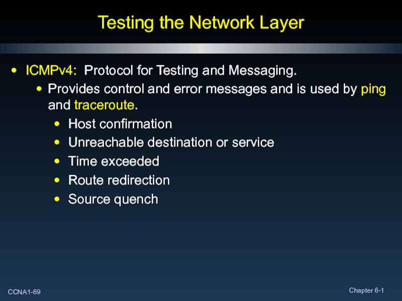
ICMPv4: Protocol for Testing and Messaging.
Provides control and
Host confirmation
Unreachable destination or service
Time exceeded
Route redirection
Source quench
