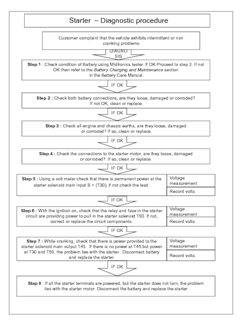
Step 1 : Check condition of Battery using Midtronics tester. If OK Proceed to step 2. If not OK then refer to the Battery Charging and Maintenance section
in the Battery Care Manual.
.
Step 2 : Check both battery connections, are they loose, damaged or corroded?
If not OK, clean or replace.
IF OK
IF OK
Step 3 : Check all engine and chassis earths, are they loose, damaged
or corroded? If so, clean or replace.
Step 4 : Check the connections to the starter motor, are they loose, damaged
or corroded? If so, clean or replace.
IF OK
IF OK
Step 8 : If all the starter terminals are powered, but the starter does not turn, the problem
lies with the starter motor. Disconnect the battery and replace the starter.
Customer complaint that the vehicle exhibits intermittent or non
cranking problems.
DIAGNOSIS
Voltage measurement
Step 5 : Using a volt meter check that there is permanent power at the starter solenoid main input B + (T30), if not check the lead.
IF OK
Record volts:
Step 7 : While cranking, check that there is power provided to the starter solenoid main output T45. If there is no power at T45 but power at T30 and T50, the problem lies with the starter. Disconnect battery and replace the starter.
Step 6 : With the ignition on, check that the relay and fuse in the starter circuit are providing power to pull in the starter solenoid T50. If not, correct or replace the circuit components.
IF OK
Voltage measurement
IF OK
Voltage measurement
Record volts:
Record volts:
