Power and Oil and Gas Industry
Physical Engineering Department
Physics 1
Voronkov Vladimir Vasilyevich
- Главная
- Разное
- Дизайн
- Бизнес и предпринимательство
- Аналитика
- Образование
- Развлечения
- Красота и здоровье
- Финансы
- Государство
- Путешествия
- Спорт
- Недвижимость
- Армия
- Графика
- Культурология
- Еда и кулинария
- Лингвистика
- Английский язык
- Астрономия
- Алгебра
- Биология
- География
- Детские презентации
- Информатика
- История
- Литература
- Маркетинг
- Математика
- Медицина
- Менеджмент
- Музыка
- МХК
- Немецкий язык
- ОБЖ
- Обществознание
- Окружающий мир
- Педагогика
- Русский язык
- Технология
- Физика
- Философия
- Химия
- Шаблоны, картинки для презентаций
- Экология
- Экономика
- Юриспруденция
Self-inductance презентация
Содержание
- 1. Self-inductance
- 2. Lecture 14 Inductunce Self-inductunce RL Circuits Energy
- 3. When the switch is thrown to its
- 4. (a) A current in the coil produces
- 5. Self-induced emf From Faraday’s law follows that
- 6. From last expression it follows that
- 7. Ideal Solenoid Inductance Combining the last expression
- 8. An inductor in a circuit opposes changes
- 10. Taking the antilogarithm of the last result:
- 11. The time constant τ is the time
- 12. Multiplying by I the expression for RL–circuit
- 13. After integration of the last formula:
- 14. Inductance for solenoid is: The magnetic
- 15. uB is the energy density of the
- 16. A cross-sectional view of two adjacent coils.
- 17. Mutual inductance depends on the geometry of
- 18. The emf induced by coil 1 in
- 19. Although the proportionality constants M12 and M21
- 20. If the capacitor is initially charged and
- 22. The solution for the equation
- 23. Then the current is: Choosing
- 24. Graph of charge versus time
- 25. Plots of UC versus t and UL
- 26. A series RLC circuit. Switch S1 is
- 27. Energy is dissipated on the resistor:
- 28. The RLC circuit is analogous to the
- 31. Units in Si Inductance L H
Слайд 1Republic of Kazakhstan
Ministry of Education and Science
Kazakh-British Technical University
Faculty of

Слайд 2Lecture 14
Inductunce
Self-inductunce
RL Circuits
Energy in a Magnetic Field
Mutual inductance
LC circuit – harmonic
oscillations
RLC circuit – damped harmonic oscillations
RLC circuit – damped harmonic oscillations

Слайд 3 When the switch is thrown to its closed position, the current
does not immediately jump from zero to its maximum value ε/R. As the current increases with time, the magnetic flux through the circuit loop due to this current also increases with time. This increasing flux creates an induced emf in the circuit. The direction of the induced emf is such that it would cause an induced current in the loop), which would establish a magnetic field opposing the change in the original magnetic field. Thus, the direction of the induced emf is opposite the direction of the emf of the battery; this results in a gradual rather than instantaneous increase in the current to its final equilibrium value. Because of the direction of the induced emf, it is also called a back emf. This effect is called self-induction because the changing flux through the circuit and the resultant induced emf arise from the circuit itself. The emf εL set up in this case is called a self-induced emf.
Self-inductance

Слайд 4 (a) A current in the coil produces a magnetic field directed
to the left.
(b) If the current increases, the increasing magnetic flux creates an induced emf in the coil having the polarity shown by the dashed battery.
(c) The polarity of the induced emf reverses if the current decreases.
 A current in the coil produces a magnetic field directed to the left. (b) If")
Слайд 5Self-induced emf
From Faraday’s law follows that the induced emf is equal
to the negative of the time rate of change of the magnetic flux. The magnetic flux is proportional to the magnetic field due to the current, which in turn is proportional to the current in the circuit. Therefore, a self-induced emf is always proportional to the time rate of change of the current:
L is a proportionality constant—called the inductance of the coil—that depends on the geometry of the coil and other physical characteristics.
L is a proportionality constant—called the inductance of the coil—that depends on the geometry of the coil and other physical characteristics.

Слайд 6From last expression it follows that
So inductance is a measure of
the opposition to a change in current.

Слайд 7Ideal Solenoid Inductance
Combining the last expression with Faraday’s law, εL =
-N dΦB/dt, we see that the inductance of a closely spaced coil of N turns (a toroid or an ideal solenoid) carrying a current I and containing N turns is


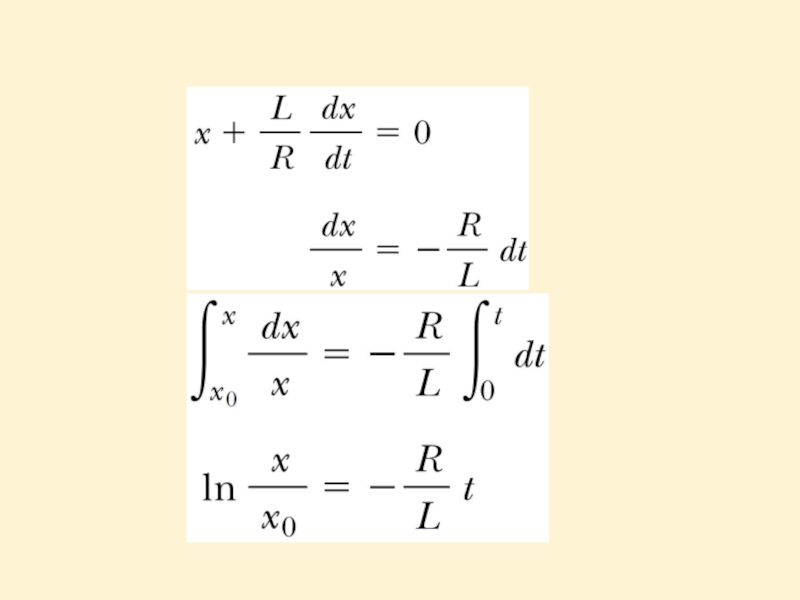
Слайд 10Taking the antilogarithm of the last result:
Because I = 0 at
t = 0, we note from the definition of x that x0 = ε/R. Hence, this last expression is equivalent to

Слайд 11 The time constant τ is the time interval required for I
to reach 0.632 (1-e-1) of its maximum value.
So the current gradually approaches its maximum:
")
Слайд 12 Multiplying by I the expression for RL–circuit we obtain:
So here Iε
is the power output of the battery, I2R is the power dissipated on the resistor, then LIdI/dt is the power delivering to the inductor. Let’s U denote as the energy stored in the inductor, then:
Energy in an Inductor

Слайд 13After integration of the last formula:
L is the inductance of the
inductor,
I is the current in the inductor,
U is the energy stored in the magnetic field of the inductor.
I is the current in the inductor,
U is the energy stored in the magnetic field of the inductor.

Слайд 14Inductance for solenoid is:
The magnetic field of a solenoid is:
Then:
Al is
the volume of the solenoid, then the energy density of the magnetic field is:
Magnetic Field Energy Density

Слайд 15uB is the energy density of the magnetic field
B is the
magnetic field vector
μ0 is the free space permeability for the magnetic field, a constant.
Though this formula was obtained for solenoid, it’s valid for any region of space where a magnetic field exists.
μ0 is the free space permeability for the magnetic field, a constant.
Though this formula was obtained for solenoid, it’s valid for any region of space where a magnetic field exists.

Слайд 16 A cross-sectional view of two adjacent coils. The current I1 in
coil 1, which has N1 turns, creates a magnetic field. Some of the magnetic field lines pass through coil 2, which has N2 turns. The magnetic flux caused by the current in coil 1 and passing through coil 2 is represented by F12. The mutual inductance M12 of coil 2 with respect to coil 1 is:
Mutual Inductance
Mutual inductance depends on the geometry of both circuits and on their orientation with respect to each other. As the circuit separation distance increases, the mutual inductance decreases because the flux linking the circuits decreases.

Слайд 17Mutual inductance depends on the geometry of both circuits and on
their orientation with respect to each other. As the circuit separation distance increases, the mutual inductance decreases because the flux linking the circuits decreases.

Слайд 18The emf induced by coil 1 in coil 2 is:
The preceding
discussion can be repeated to show that there is a mutual inductance M21. The emf induced by coil 1 in coil 2 is:
In mutual induction, the emf induced in one coil is always proportional to the rate at which the current in the other coil is changing.
In mutual induction, the emf induced in one coil is always proportional to the rate at which the current in the other coil is changing.

Слайд 19 Although the proportionality constants M12 and M21 have been obtained separately,
it can be shown that they are equal. Thus, with M12 = M21 = M, the expressions for induced emf takes the form:
These two expression are similar to that for the self-induced emf: ε = - L(dI/dt).
The unit of mutual inductance is the henry.
These two expression are similar to that for the self-induced emf: ε = - L(dI/dt).
The unit of mutual inductance is the henry.

Слайд 20If the capacitor is initially charged and the switch is then
closed, we find that both the current in the circuit and the charge on the capacitor oscillate between maximum positive and negative values.
We assume:
the resistance of the circuit is zero, then no energy is dissipated,
energy is not radiated away from the circuit.
We assume:
the resistance of the circuit is zero, then no energy is dissipated,
energy is not radiated away from the circuit.
LC Circuit Oscillations

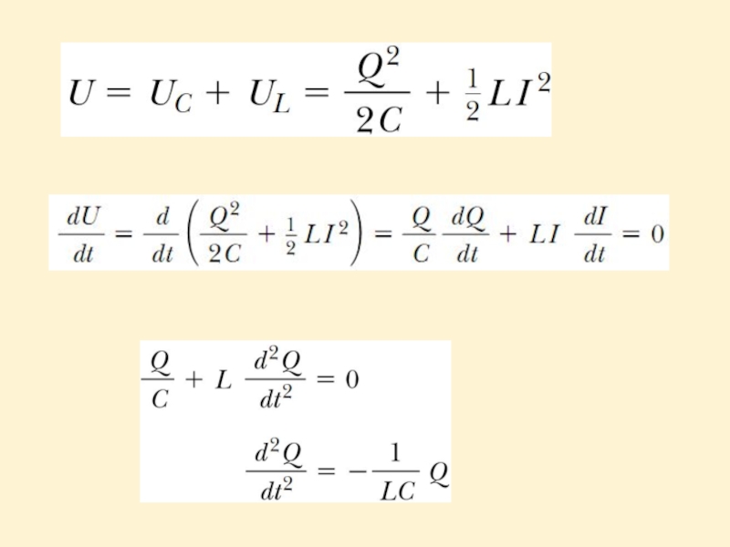
Слайд 22
The solution for the equation is:
The angular frequency of the
oscillations depends solely on the inductance and capacitance of the circuit. This is the natural frequency (частота собственных колебаний) of oscillation of the LC circuit.

Слайд 23Then the current is:
Choosing the initial conditions: at t = 0,
I = 0 and Q = Qmax we determine that φ=0.
Eventually, the charge in the capacitor and the current in the inductor are:
Eventually, the charge in the capacitor and the current in the inductor are:

Слайд 24
Graph of charge versus time
and
Graph of current versus time for
a resistanceless, nonradiating LC circuit.
NOTE: Q and I are 90° out of phase with each other.
NOTE: Q and I are 90° out of phase with each other.

Слайд 25Plots of UC versus t and UL versus t for a
resistanceless, nonradiating LC circuit.
The sum of the two curves is a constant and equal to the total energy stored in the circuit.
The sum of the two curves is a constant and equal to the total energy stored in the circuit.

Слайд 26 A series RLC circuit. Switch S1 is closed and the capacitor
is charged. S1 is then opened and, at t = 0, switch S2 is closed.
RLC circuit

Слайд 27Energy is dissipated on the resistor:
Using the equation for dU/dt in
the LC-circuit (slide 2):
Using that I=dQ/dt:
Using that I=dQ/dt:
:Using")
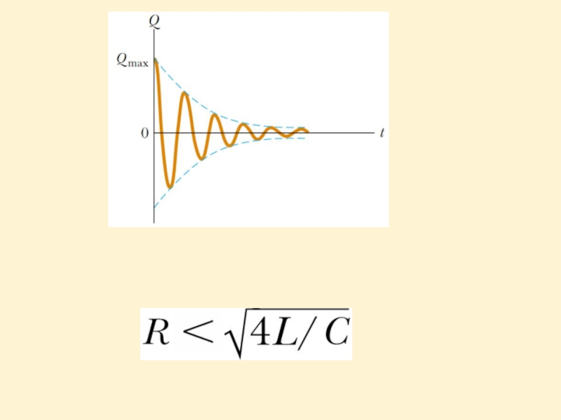
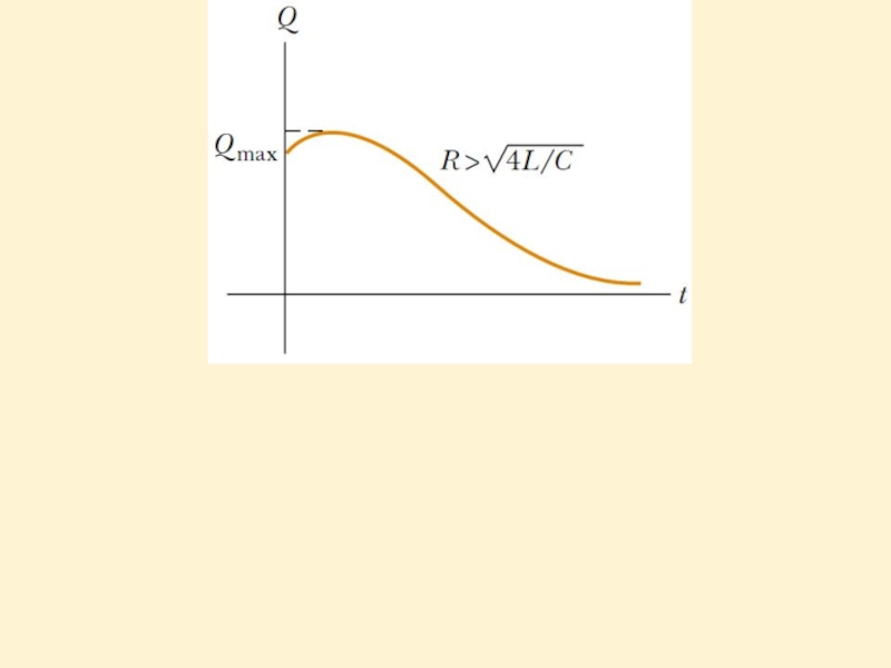
Слайд 28The RLC circuit is analogous to the damped harmonic oscillator, where
R is damping coefficient.
Here b is damping coefficient. When b=0, we have pure harmonic oscillations.
Solution is:
RC is the critical resistance:
When RWhen R>RC oscillations are damped unharmonic.
Here b is damping coefficient. When b=0, we have pure harmonic oscillations.
Solution is:
RC is the critical resistance:
When R

: 1H=V*s/AMutual Inductance M H (henry): 1H=V*s/A")