- Главная
- Разное
- Дизайн
- Бизнес и предпринимательство
- Аналитика
- Образование
- Развлечения
- Красота и здоровье
- Финансы
- Государство
- Путешествия
- Спорт
- Недвижимость
- Армия
- Графика
- Культурология
- Еда и кулинария
- Лингвистика
- Английский язык
- Астрономия
- Алгебра
- Биология
- География
- Детские презентации
- Информатика
- История
- Литература
- Маркетинг
- Математика
- Медицина
- Менеджмент
- Музыка
- МХК
- Немецкий язык
- ОБЖ
- Обществознание
- Окружающий мир
- Педагогика
- Русский язык
- Технология
- Физика
- Философия
- Химия
- Шаблоны, картинки для презентаций
- Экология
- Экономика
- Юриспруденция
МЭМС и НЭМС: электронные системы, жидкостные вентили, насосы и биомедицинские системы презентация
Содержание
- 1. МЭМС и НЭМС: электронные системы, жидкостные вентили, насосы и биомедицинские системы
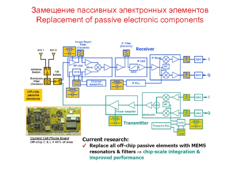
- 2. Замещение пассивных электронных элементов Replacement of passive electronic components
- 3. Индуктивность Microinductor The PARC inductor: (a) scanning-electron
- 4. Индуктивность - последовательность производства НЭМС Fabrication of microinductor
- 5. Переменная емкость Tunable capacitor
- 6. Резонатор Resonator Illustration of a micromachined folded-beam
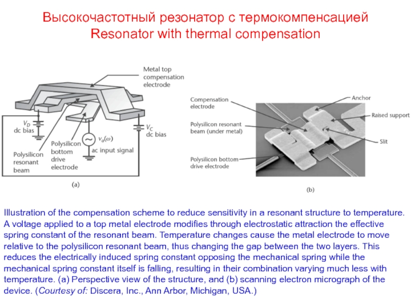
- 7. Высокочастотный резонатор с термокомпенсацией Resonator with thermal
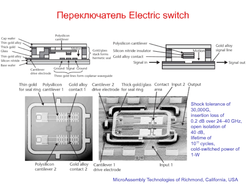
- 8. Переключатель Electric switch MicroAssembly Technologies of Richmond,
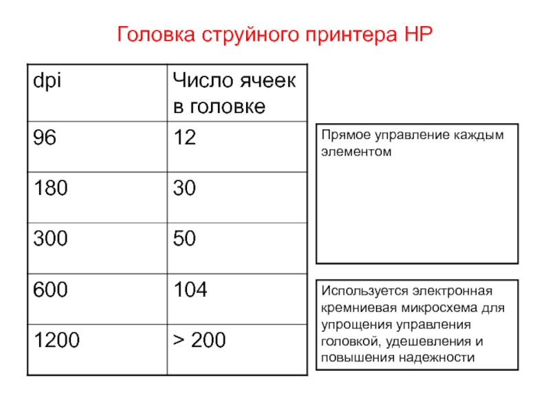
- 9. Головка струйного принтера HP Head of HP
- 10. Головка струйного принтера HP - последовательность производства. Head of HP inc-jet printer - production steps
- 11. Головка струйного принтера HP Используется электронная кремниевая
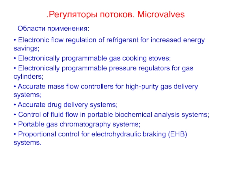
- 12. .Регуляторы потоков. Microvalves • Electronic flow regulation
- 13. Нормально-открытый регулятор потока Normally open microvalve
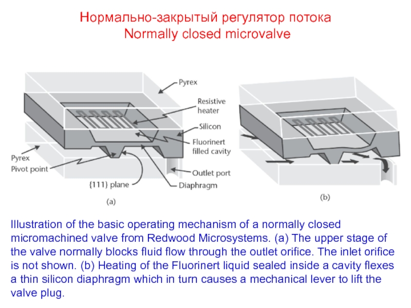
- 14. Нормально-закрытый регулятор потока Normally closed microvalve
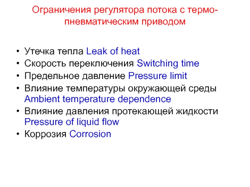
- 15. Ограничения регулятора потока с термо-пневматическим приводом Утечка
- 16. Микроклапан с приводом из металла с памятью
- 17. Микроклапан – последовательность изготовления привода Normally closed
- 18. Микронасос Micropump Illustration of a cutout of
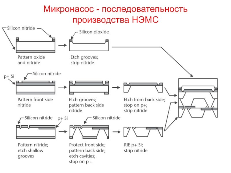
- 19. Микронасос - последовательность производства НЭМС
- 20. Микрожидкостные системы Microfluidic systems
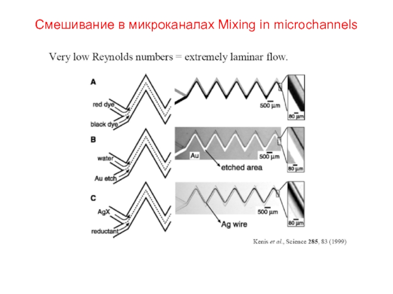
- 21. Смешивание в микроканалах Laminar flow and mixing
- 22. Смешивание в микроканалах Mixing in microchannels
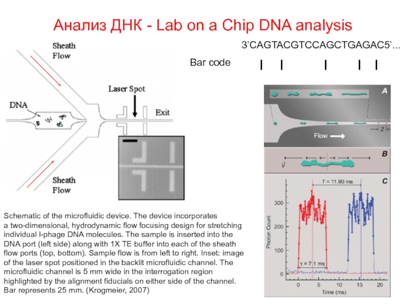
- 23. Анализ ДНК - Lab on a Chip
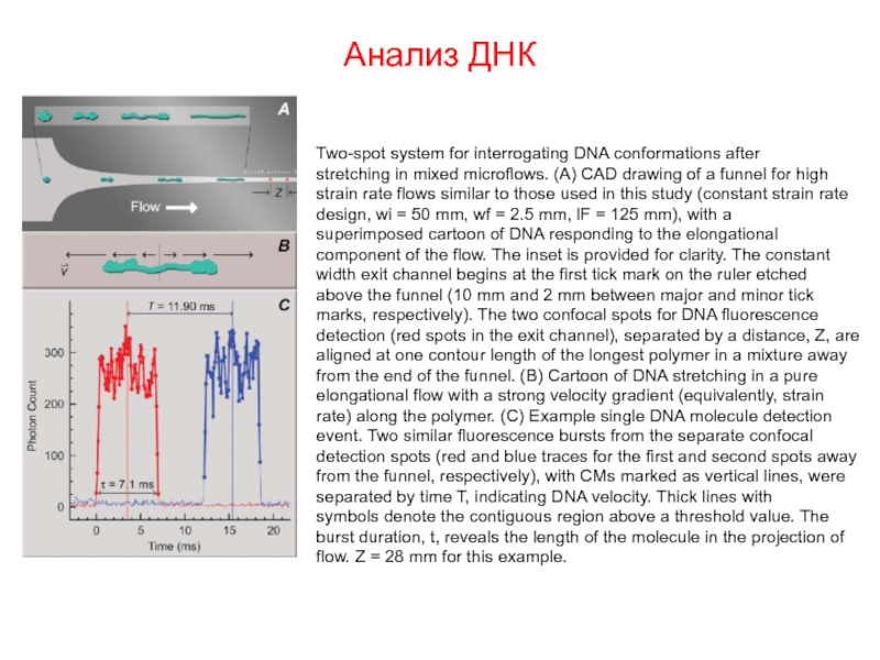
- 24. Анализ ДНК Two-spot system for interrogating DNA
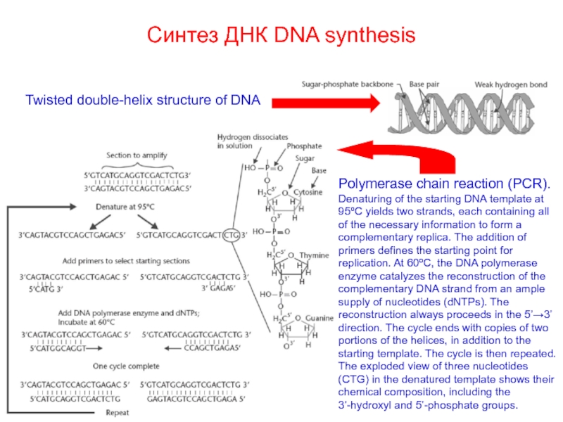
- 25. Синтез ДНК DNA synthesis Twisted double-helix structure
- 26. Цепная реакция полимеразы в МЭМС Polymerase chain
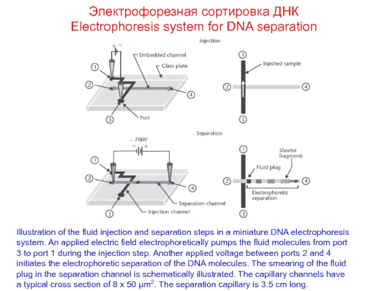
- 27. Электрофорезная сортировка ДНК Electrophoresis system for DNA
- 28. Микроэлектроды Microelectrode array Cross section of
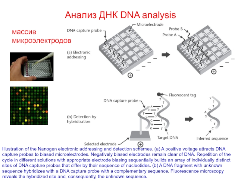
- 29. Анализ ДНК DNA analysis Illustration of the
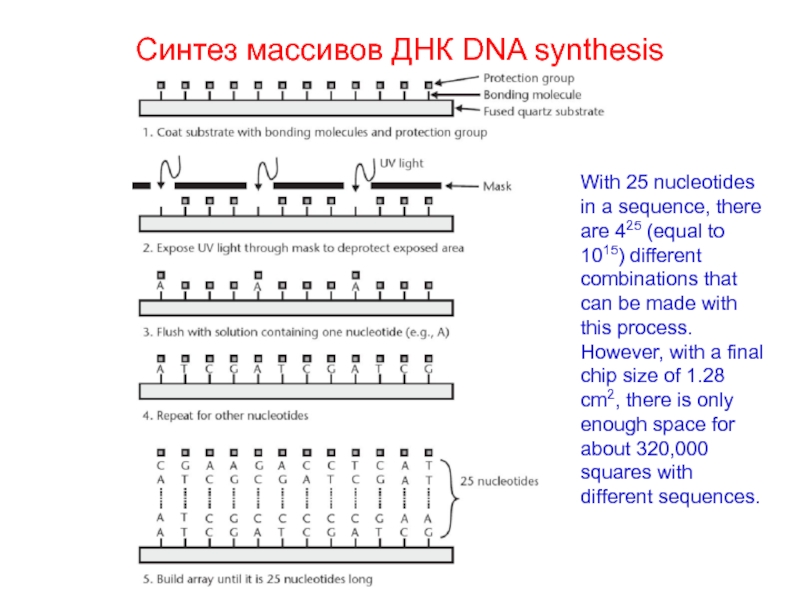
- 30. Синтез массивов ДНК DNA synthesis With 25
- 31. Анализ крови – экспресная диагностика рака Cancer tumor detection
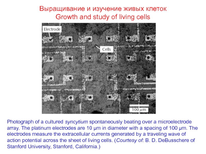
- 32. Выращивание и изучение живых клеток Growth
- 33. Интегрированная биосистема Integrated biosystem
- 34. Рынок НЭМС Analysis of Worldwide MEMS Markets
- 35. МЭМС и НЭМС представляют собой обширное семейство
- 36. The end !
Слайд 1Наномеханика
Nanomechanics of materials and systems
Лекции 15
МЭМС и НЭМС:
электронные системы,
Слайд 3Индуктивность Microinductor
The PARC inductor: (a) scanning-electron micrograph (SEM) of a five-turn
Слайд 6Резонатор Resonator
Illustration of a micromachined folded-beam comb-drive resonator. The left comb
Добротность Q
кварц Q≈10000
RLC Q<1000
НЭМС:
вакуум Q>50000
воздух Q<50
k = E t (w/L)3
E = 160 GPa
t = 2 μm
w = 2 μm
L = 33 μm
m = 5.7 10-11 kg
f = 190 kHz
Слайд 7Высокочастотный резонатор с термокомпенсацией
Resonator with thermal compensation
Illustration of the compensation scheme
Слайд 8Переключатель Electric switch
MicroAssembly Technologies of Richmond, California, USA
Shock tolerance of
30,000G,
insertion loss of 0.2 dB over 24–40 GHz,
open isolation of 40 dB,
lifetime of 1011 cycles,
cold-switched power of 1-W
Слайд 9Головка струйного принтера HP
Head of HP inc-jet printer
Heater temperature 250 °C,
Слайд 10Головка струйного принтера HP - последовательность производства. Head of HP inc-jet
Слайд 11Головка струйного принтера HP
Используется электронная кремниевая микросхема для упрощения управления головкой,
Прямое управление каждым элементом
Слайд 12.Регуляторы потоков. Microvalves
• Electronic flow regulation of refrigerant for increased energy
• Electronically programmable gas cooking stoves;
• Electronically programmable pressure regulators for gas cylinders;
• Accurate mass flow controllers for high-purity gas delivery systems;
• Accurate drug delivery systems;
• Control of fluid flow in portable biochemical analysis systems;
• Portable gas chromatography systems;
• Proportional control for electrohydraulic braking (EHB) systems.
Области применения:
Слайд 13Нормально-открытый регулятор потока
Normally open microvalve
Illustration of a normally open valve
The flow rate ranges from 0.1 sccm up to 1,500 sccm. The maximum inlet supply pressure is 690 kPa, the switching time is typically 0.5s, and the corresponding average power consumption is 500 mW.
Слайд 14Нормально-закрытый регулятор потока
Normally closed microvalve
Illustration of the basic operating
Слайд 15Ограничения регулятора потока с термо-пневматическим приводом
Утечка тепла Leak of heat
Скорость переключения
Предельное давление Pressure limit
Влияние температуры окружающей среды Ambient temperature dependence
Влияние давления протекающей жидкости Pressure of liquid flow
Коррозия Corrosion
Слайд 16Микроклапан с приводом из металла с памятью формы Normally closed valve
Assembly of the micromachined, normally closed valve with TiNi alloy actuator. The beryllium-copper spring pushes a sapphire ball against the silicon poppet to close the flow orifice. Resistive heating of the TiNi spring above its transition temperature causes it to recover its original flat (undeflected) shape. The actuation pulls the poppet away from the orifice, hence permitting fluid flow. (After: A. D. Johnson, TiNi Alloy Company of San Leandro, California.)
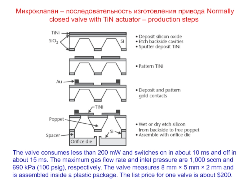
Слайд 17Микроклапан – последовательность изготовления привода Normally closed valve with TiN actuator
The valve consumes less than 200 mW and switches on in about 10 ms and off in about 15 ms. The maximum gas flow rate and inlet pressure are 1,000 sccm and 690 kPa (100 psig), respectively. The valve measures 8 mm × 5 mm × 2 mm and is assembled inside a plastic package. The list price for one valve is about $200.
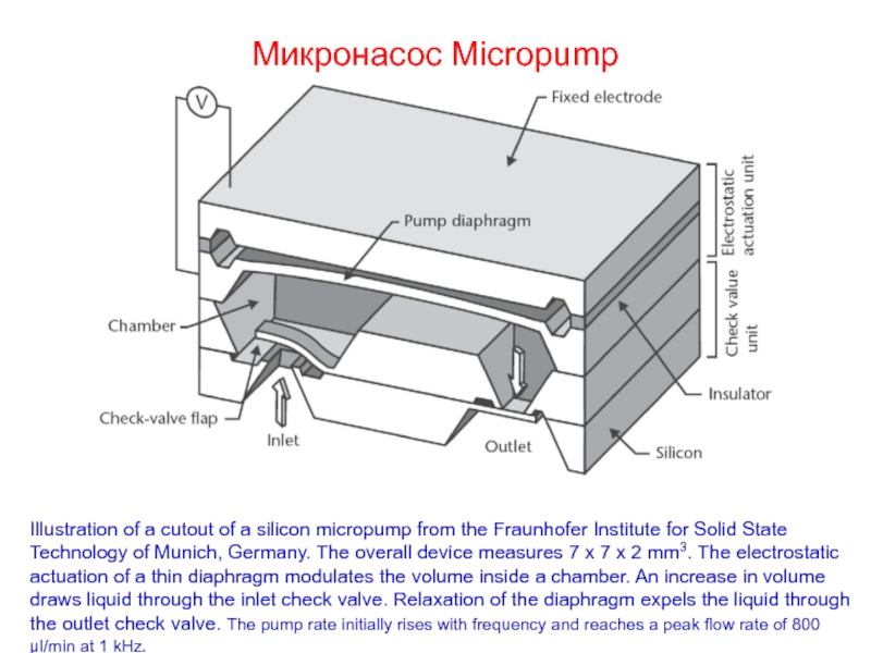
Слайд 18Микронасос Micropump
Illustration of a cutout of a silicon micropump from the
μl/min at 1 kHz.
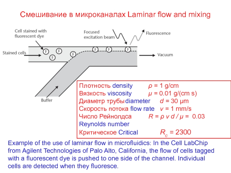
Слайд 21Смешивание в микроканалах Laminar flow and mixing
Example of the use of
Плотность density ρ = 1 g/cm
Вязкость viscosity μ = 0.01 g/(cm s)
Диаметр трубы diameter d = 30 μm
Скорость потока flow rate v = 1 mm/s
Число Рейнолдса R = ρ v d / μ = 0.03
Reynolds number
Критическое Critical Rс = 2300
Слайд 23Анализ ДНК - Lab on a Chip DNA analysis
Schematic of the
a two-dimensional, hydrodynamic flow focusing design for stretching
individual l-phage DNA molecules. The sample is inserted into the
DNA port (left side) along with 1X TE buffer into each of the sheath
flow ports (top, bottom). Sample flow is from left to right. Inset: image
of the laser spot positioned in the backlit microfluidic channel. The
microfluidic channel is 5 mm wide in the interrogation region
highlighted by the alignment fiducials on either side of the channel.
Bar represents 25 mm. (Krogmeier, 2007)
Слайд 24Анализ ДНК
Two-spot system for interrogating DNA conformations after
stretching in mixed microflows.
strain rate flows similar to those used in this study (constant strain rate
design, wi = 50 mm, wf = 2.5 mm, lF = 125 mm), with a
superimposed cartoon of DNA responding to the elongational
component of the flow. The inset is provided for clarity. The constant
width exit channel begins at the first tick mark on the ruler etched
above the funnel (10 mm and 2 mm between major and minor tick
marks, respectively). The two confocal spots for DNA fluorescence
detection (red spots in the exit channel), separated by a distance, Z, are
aligned at one contour length of the longest polymer in a mixture away
from the end of the funnel. (B) Cartoon of DNA stretching in a pure
elongational flow with a strong velocity gradient (equivalently, strain
rate) along the polymer. (C) Example single DNA molecule detection
event. Two similar fluorescence bursts from the separate confocal
detection spots (red and blue traces for the first and second spots away
from the funnel, respectively), with CMs marked as vertical lines, were
separated by time T, indicating DNA velocity. Thick lines with
symbols denote the contiguous region above a threshold value. The
burst duration, t, reveals the length of the molecule in the projection of
flow. Z = 28 mm for this example.
Слайд 25Синтез ДНК DNA synthesis
Twisted double-helix structure of DNA
Polymerase chain reaction (PCR).
Слайд 26Цепная реакция полимеразы в МЭМС
Polymerase chain reaction in MEMS
Illustrations of (a)
Слайд 27Электрофорезная сортировка ДНК
Electrophoresis system for DNA separation
Illustration of the fluid
Слайд 28Микроэлектроды Microelectrode array
Cross section of a microelectrode array showing two
Слайд 29Анализ ДНК DNA analysis
Illustration of the Nanogen electronic addressing and detection
массив
микроэлектродов
Слайд 30Синтез массивов ДНК DNA synthesis
With 25 nucleotides in a sequence, there
Слайд 32Выращивание и изучение живых клеток
Growth and study of living cells
Photograph
Слайд 34Рынок НЭМС
Analysis of Worldwide MEMS Markets
(in Millions of U.S. Dollars)
In-Stat/MDR,
6909 East Greenway Parkway, Suite 250, Scottsdale, AZ 85254,
North America 139
Germany 34
France 20
United Kingdom 14
Benelux 17
Scandinavia 20
Switzerland 14
Rest of Europe 10
Japan 41
Rest of Asia 31
Geographical Distribution of the World MEMS Production Facilities
Yole Developement, “World MEMS Fab,” 45 Rue Sainte Genevieve, 69006 Lyon, France
Слайд 35МЭМС и НЭМС представляют собой обширное семейство портативных приборов, датчиков и
Основным материалом НЭМС является кремний. Material of choice for MEMS is Si.
Технологии НЭМС разработаны на базе технологий полупроводниковой электроники. MEMS technology is taken from electronics
Уровень технологии НЭМС обеспечивает массовое производство надежных приборов и устройств различного назначения. NEMS technology allows mass production.
Основными областями применения НЭМС являются биология и медицина, системы безопасности, системы связи и навигации, электроника и фотоника. Major application areas are biology, medicine, safety systems, navigation, communications, electronics, photonics
НЭМС представляют собой значимый и быстрорастущий сектор современной экономики. NEMS market is big and fast growing.
Заключение Conclusion
World smallest car
World smallest guitar
Virtual reality system
