- Главная
- Разное
- Дизайн
- Бизнес и предпринимательство
- Аналитика
- Образование
- Развлечения
- Красота и здоровье
- Финансы
- Государство
- Путешествия
- Спорт
- Недвижимость
- Армия
- Графика
- Культурология
- Еда и кулинария
- Лингвистика
- Английский язык
- Астрономия
- Алгебра
- Биология
- География
- Детские презентации
- Информатика
- История
- Литература
- Маркетинг
- Математика
- Медицина
- Менеджмент
- Музыка
- МХК
- Немецкий язык
- ОБЖ
- Обществознание
- Окружающий мир
- Педагогика
- Русский язык
- Технология
- Физика
- Философия
- Химия
- Шаблоны, картинки для презентаций
- Экология
- Экономика
- Юриспруденция
Internal сombustion engine. Thermodynamic analysis. Engine cycles презентация
Содержание
- 1. Internal сombustion engine. Thermodynamic analysis. Engine cycles
- 2. Basic terms and definitions An ideal
- 3. Basic terms and definitions specific volume of
- 4. ENGINE CYCLES This chapter studies the
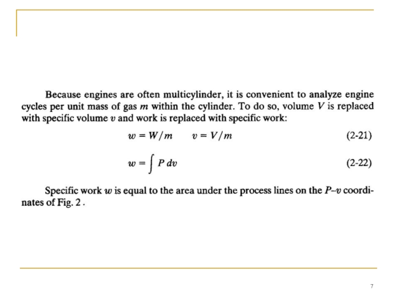
- 5. WORK
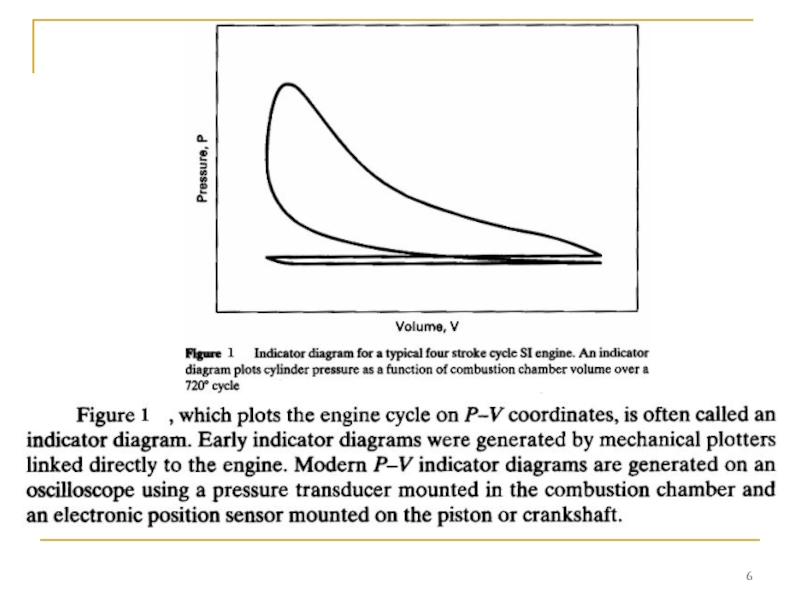
- 9. If P represents the pressure inside the
- 11. It then decreases with decreasing engine speed
- 12. AIR-STANDARD CYCLES The cycle experienced in
- 13. AIR-STANDARD CYCLES 1. The gas mixture in
- 14. AIR-STANDARD CYCLES (b) Compression strokes and expansion
- 15. In air-standard cycles, air is considered an
- 17. For thermodynamic analysis the specific heats of
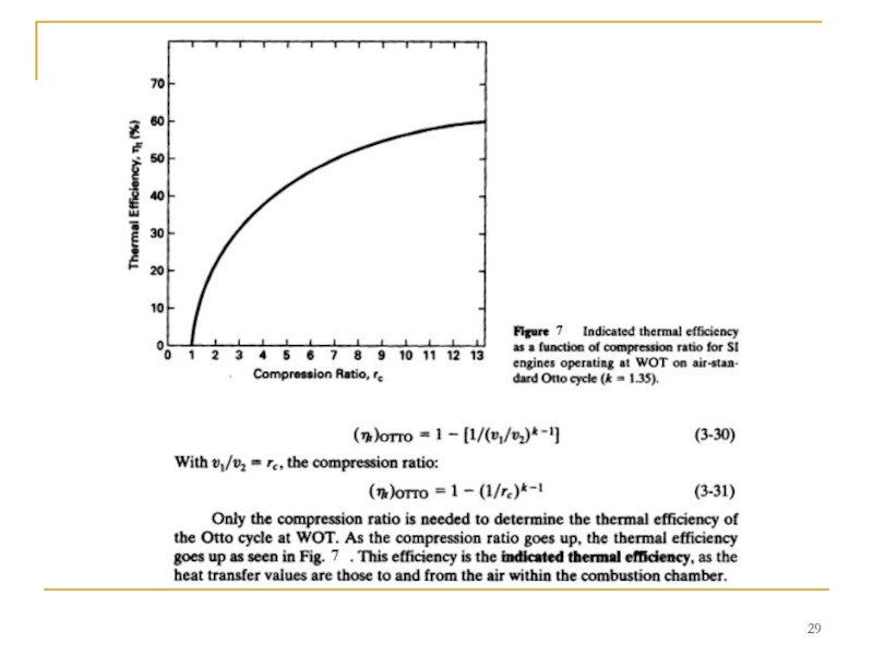
- 20. OTTO CYCLE This is a good approximation
- 21. The second stroke of the cycle is
- 22. The power stroke of the real engine
- 23. The last stroke of the four-stroke cycle
- 24. When analyzing an Otto cycle, it is
- 30. REAL AIR-FUEL ENGINE CYCLES The actual
- 31. 2. Air-standard analysis treats the fluid flow
- 32. 4. Combustion requires a short but finite
- 33. 7. Engine valves require a finite time
- 34. DIESEL CYCLE This kept the pressure at
- 39. If reptesentative numbers are introduced into Eq.
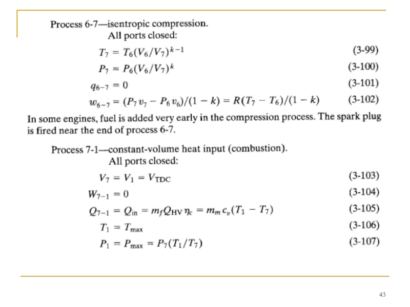
- 40. TWO-STROKE CYCLE
- 42. Process 3-4-5-intake, and exhaust scavenging. Exhaust port
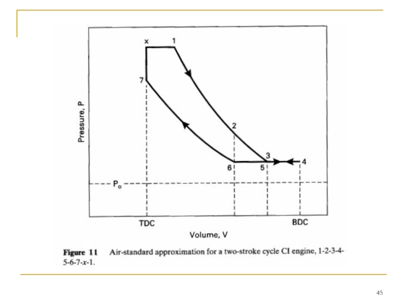
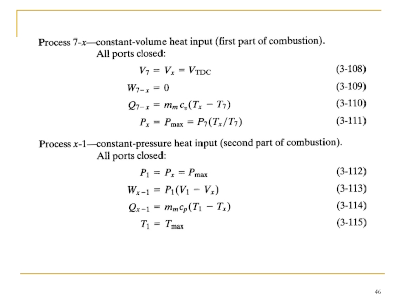
- 44. TWO-STROKE CI ENGINE CYCLE Many compression ignition
- 47. SUMMARY This chapter reviewed the basic cycles

Слайд 2Basic terms and definitions
An ideal gas is a theoretical is
Enthalpy is a measure of the total energy is a measure of the total energy of a thermodynamic system is a measure of the total energy of a thermodynamic system. It includes the internal energy is a measure of the total energy of a thermodynamic system. It includes the internal energy, which is the energy required to create a system, and the amount of energy required to make room for it by displacing its environment is a measure of the total energy of a thermodynamic system. It includes the internal energy, which is the energy required to create a system, and the amount of energy required to make room for it by displacing its environment and establishing its volume is a measure of the total energy of a thermodynamic system. It includes the internal energy, which is the energy required to create a system, and the amount of energy required to make room for it by displacing its environment and establishing its volume and pressure.
An isentropic process or isoentropic process is one in which, for purposes of engineering analysis and calculation, one may assume that the process takes place from initiation to completion without an increase or decrease in the entropy of the system, i.e., the entropy of the system remains constant. It can be proven that any reversible is one in which, for purposes of engineering analysis and calculation, one may assume that the process takes place from initiation to completion without an increase or decrease in the entropy of the system, i.e., the entropy of the system remains constant. It can be proven that any reversible adiabatic process is an isentropic process. A simple more common definition of isentropic would be "No change in entropy".
Entropy in statistical mechanics is a measure of the number of specific ways in which a system may be arranged, often taken to be a measure of "disorder"; the higher the entropy, the higher the disorder. The entropy of an isolated system never decreases, because isolated systems spontaneously evolve towards thermodynamic equilibrium – the state of maximum entropy.
Entropy is a mathematically-defined thermodynamic quantity that helps to account for the flow of energy through a thermodynamic process.

Слайд 3Basic terms and definitions
specific volume of gas - удельный объем газа;
specific
specific internal energy - удельная внутренняя энергия; specific heats – теплоемкости;
specific work – удельная работа;
mass flow rate - eдельный массовый расход;
heat transfer rate for unit mass - теплопроизводительность для единицы массы;
heat transfer rate - скорость теплопередачи;
WOT (Wide-Open Throttle) – полностью открытый дроссель;
Bottom-Dead-Center (BDC);
Top-Dead-Center (TDC);
When an occurrence in a cycle happens before TDC, it is often abbreviated bTDC or bTe;
When the occurrence happens after TDC, it will be abbreviated aTDC or aTe;
During an engine cycle things can happen before bottom-dead-center, bBDC or bBC, and after bottom-dead-center, aBDC or aBe;
crevice flow – щелевой поток;
blowby – прорыв газов;

Слайд 4ENGINE CYCLES
This chapter studies the basic cycles used in reciprocating internal
The most common four-stroke SI and CI cycles are analyzed in detail using air-standard analysis.


Слайд 9 If P represents the pressure inside the cylinder combustion chamber, then
ωb = ω i - ω t (2-23)
where: ω i = indicated specific work generated inside combustion chamber;
ω t = specific work lost due to friction and parasitic loads.
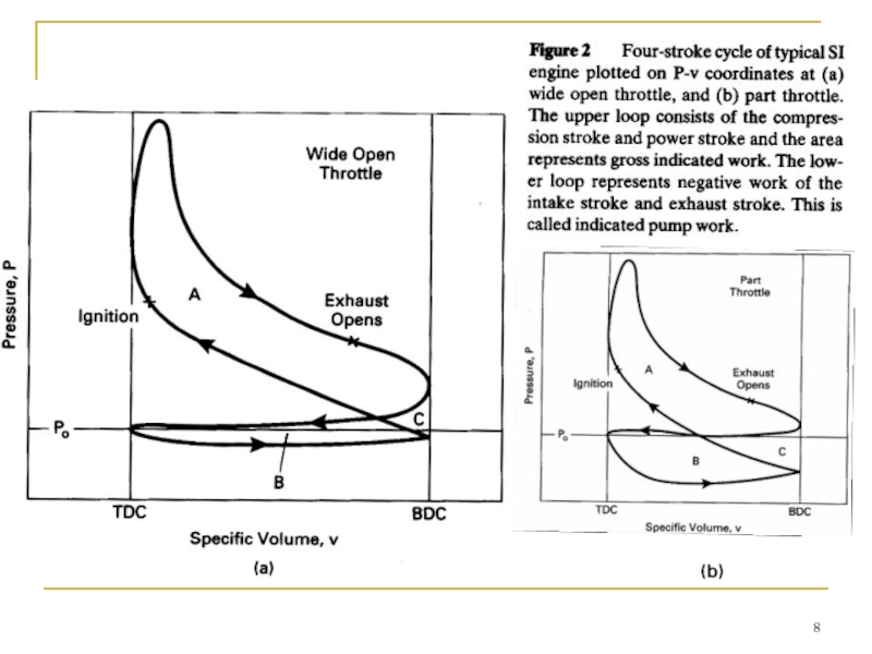
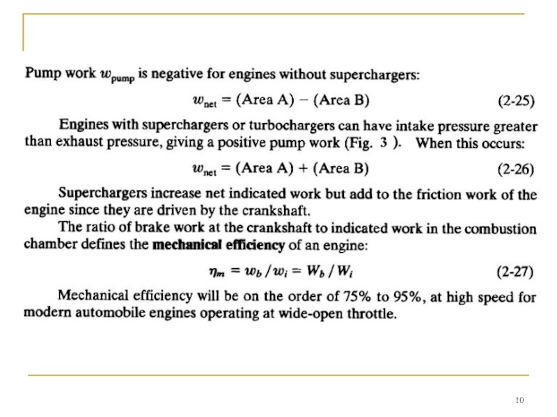
The upper loop of the engine cycle in Fig. 2 consists of the compression and power strokes where output work is generated and is called the gross indicated work (areas A and C in Fig. 2). The lower loop, which includes the intake and exhaust stroke, is called pump work and absorbs work from the engine (areas B and C).
Net indicated work is:
 and the")
Слайд 11 It then decreases with decreasing engine speed to zero at idle
Care should be taken when using the terms "gross work" and "net work". In some older literature and textbooks, net work (or net power) meant the output of an engine with all components, while gross work (or gross power) meant the output of the engine with fan and exhaust system removed.

Слайд 12AIR-STANDARD CYCLES
The cycle experienced in the cylinder of an internal combustion
First, air (CI engine) or air mixed with fuel (SI engine) is ingested and mixed with the slight amount of exhaust residue remaining from the previous cycle. This mixture is then compressed and combusted, changing the composition to exhaust products consisting largely of CO2, H20, and N2 with many other lesser components.
Then, after an expansion process, the exhaust valve is opened and this gas mixture is expelled to the surroundings. Thus, it is an open cycle with changing composition, a difficult system to analyze. To make the analysis of the engine cycle much more manageable, the real cycle is approximated with an ideal air-standard cycle which differs from the actual by the following:

Слайд 13AIR-STANDARD CYCLES
1. The gas mixture in the cylinder is treated as
2. The real open cycle is changed into a closed cycle by assuming that the gases being exhausted are fed back into the intake system. This works with ideal air-standard cycles, as both intake gases and exhaust gases are air. Closing the cycle simplifies the analysis.
3. The combustion process is replaced with a heat addition term Qin of equal energy value. Air alone cannot combust.
4. The open exhaust process, which carries a large amount of enthalpy out of the system, is replaced with a closed system heat rejection process Qout of equal energy value.
5. Actual engine processes are approximated with ideal processes.
(a) The almost-constant-pressure intake and exhaust strokes are assumed to be constant pressure. At WOT (Wide-Open Throttle), the intake stroke is assumed to be at a pressure Po of one atmosphere. At partially closed throttle or when supercharged, inlet pressure will be some constant value other than one atmosphere. The exhaust stroke pressure is assumed constant at one atmosphere.

Слайд 14AIR-STANDARD CYCLES
(b) Compression strokes and expansion strokes are approximated by isentropic
(c) The combustion process is idealized by a constant-volume process (SI cycle), a constant-pressure process (CI cycle), or a combination of both (CI Dual cycle).
(d) Exhaust blowdown is approximated by a constant-volume process.
(e) All processes are considered reversible.
 Compression strokes and expansion strokes are approximated by isentropic processes. To be truly")
Слайд 15 In air-standard cycles, air is considered an ideal gas such that

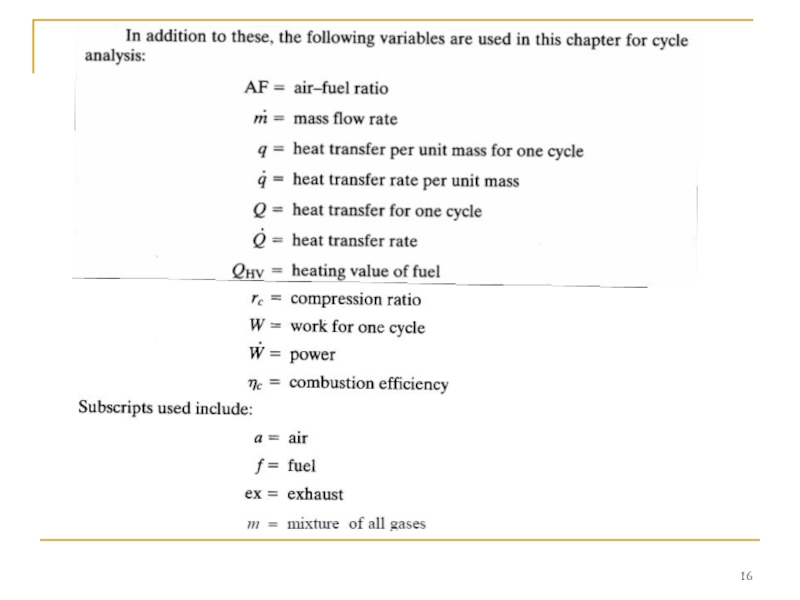
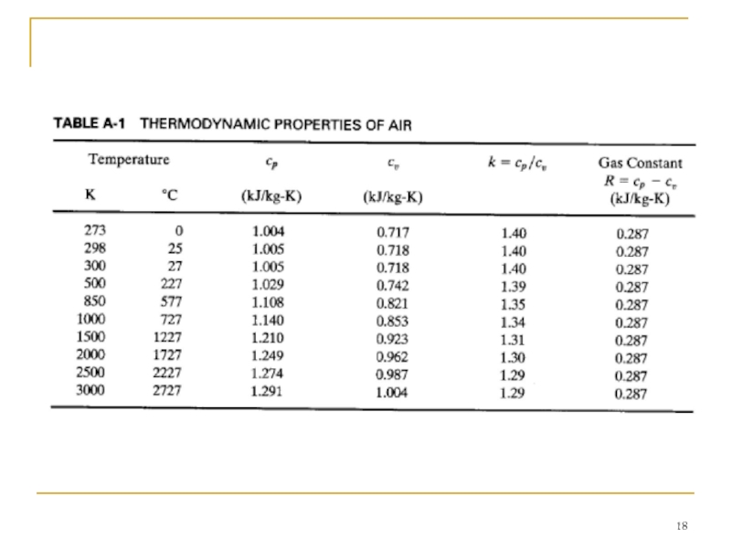
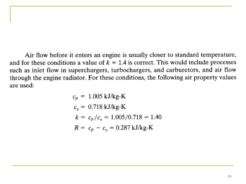
Слайд 17 For thermodynamic analysis the specific heats of air can be treated
In this chapter, constant specific heat analysis will be used. Because of the high temperatures and large temperature range experienced during an engine cycle, the specific heats and ratio of specific heats k do vary by a fair amount (see Table A-I). At the low-temperature end of a cycle during intake and start of compression, a value of k = 1.4 is correct. However, at the end of combustion the temperature has risen such that k = 1.3 would be more accurate. A constant average value between these extremes is found to give better results than a standard condition (25°C) value, as is often used in elementary thermodynamics textbooks. When analyzing what occurs within engines during the operating cycle and exhaust flow, this book uses the following air property values:

Слайд 20OTTO CYCLE
This is a good approximation to the inlet process of
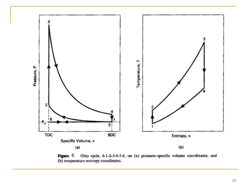
The cycle of a four-stroke, SI, naturally aspirated engine at WOT is shown in Fig. 4. This is the cycle of most automobile engines and other four-stroke SI engines. For analysis, this cycle is approximated by the air-standard cycle shown in Fig. 5. This ideal air-standard cycle is called an Otto cycle, named after one of the early developers of this type of engine.
The intake stroke of the Otto cycle starts with the piston at TDC and is a
constant-pressure process at an inlet pressure of one atmosphere (process 6-1 in Fig. 5).

Слайд 21 The second stroke of the cycle is the compression stroke, which
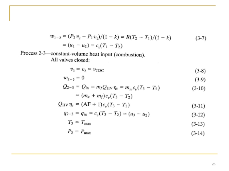
The compression stroke is followed by a constant-volume heat input process 2-3 at TDC.
This replaces the combustion process of the real engine cycle, which occurs at close to constant-volume conditions. In a real engine combustion is started slightly bTDC, reaches its maximum speed near TDC, and is terminated a little aTDC. During combustion or heat input, a large amount of energy is added to the air within the cylinder. This energy raises the temperature of the air to very high values, giving peak cycle temperature at point 3. This increase in temperature during a closed constant-volume process results in a large pressure rise also. Thus, peak cycle pressure is also reached at point 3.

Слайд 22 The power stroke of the real engine cycle is approximated with
The end of the power stroke is affected by the exhaust valve being opened before BDC. During the power stroke, values of both the temperature and pressure within the cylinder decrease as volume increases from TDC to BDC.
Near the end of the power stroke of a real engine cycle, the exhaust valve is opened and the cylinder experiences exhaust blowdown. A large amount of exhaust gas is expelled from the cylinder, reducing the pressure to that of the exhaust manifold. The exhaust valve is opened bBDC to allow for the finite time of blowdown to occur. It is desirable for blowdown to be complete by BDC so that there is no high pressure in the cylinder to resist the piston in the following exhaust stroke.
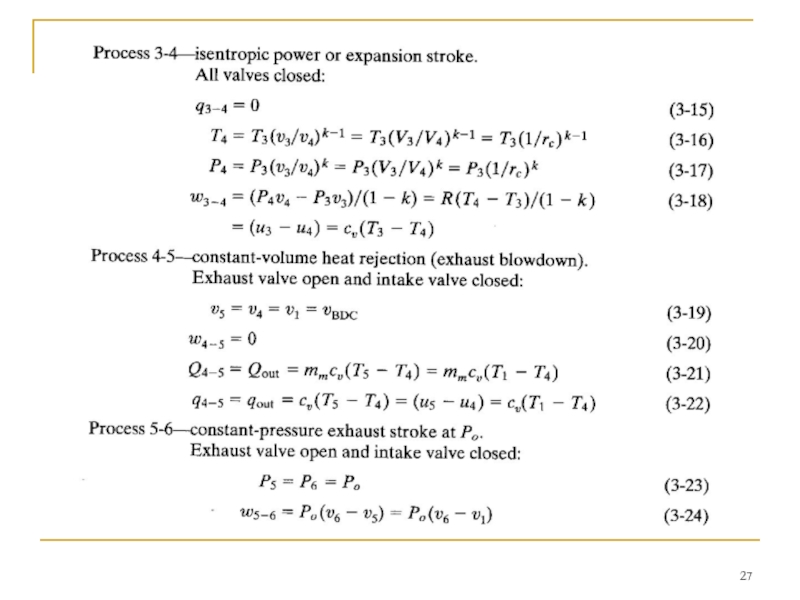
The very high pressure and enthalpy values within the system at TDC generate the power stroke (or expansion stroke) which follows combustion (process 3-4).
High pressure on the piston face forces the piston back towards BDC and produces the work and power output of the engine.

Слайд 23 The last stroke of the four-stroke cycle now occurs as the
At the end of the exhaust stroke the engine has experienced two revolutions, the piston is again at TDC, the exhaust valve closes, the intake valve opens, and a new cycle begins.
Blowdown in a real engine is therefore almost, but not quite, constant volume. A large quantity of enthalpy is carried away with the exhaust gases, limiting the thermal efficiency of the engine. The Otto cycle replaces the exhaust blowdown open-system process of the real cycle with a constant-volume pressure reduction, closed-system process 4-5. Enthalpy loss during this process is replaced with heat rejection in the engine analysis. Pressure within the cylinder at the end of exhaust blowdown has been reduced to about one atmosphere, and the temperature has been substantially reduced by expansion cooling.

Слайд 24 When analyzing an Otto cycle, it is more convenient to work

Слайд 30REAL AIR-FUEL ENGINE CYCLES
The actual cycle experienced by an internal combustion
1. Real engines operate on an open cycle with changing composition. Not only does the inlet gas composition differ from what exits, but often the mass flow rate is not the same. Those engines which add fuel into the cylinders after air induction is complete (CI engines and some SI engines) change the amount of mass in the gas composition part way through the cycle. There is a greater gaseous mass exiting the engine in the exhaust than what entered in the induction process. This can be on the order of several percent. Other engines carry liquid fuel droplets with the inlet air which are idealized as part of the gaseous mass in air-standard analysis. During combustion, total mass remains about the same but molar quantity changes. Finally, there is a loss of mass during the cycle due to crevice flow and blowby past the pistons. Most of crevice flow is a temporary loss of mass from the cylinder, but because it is greatest at the start of the power stroke, some output work is lost during expansion. Blowby can decrease the amount of mass in the cylinders by as much as 1% during compression and combustion.

Слайд 31 2. Air-standard analysis treats the fluid flow through the entire engine
Even if all fluid in an engine cycle were air, some error would be introduced by assuming it to be an ideal gas with constant specific heats in air-standard analysis. At the low pressures of inlet and exhaust, air can accurately be treated as an ideal gas, but at the higher pressures during combustion, air will deviate from ideal gas behavior.
A more serious error is introduced by assuming constant specific heats for the analysis. Specific heats of a gas have a fairly strong dependency on temperature and can vary as much as 30% in the temperature range of an engine (for air, cp = 1.004 kJ/kg-K at 300 K and cp = 1.292 kJ/kg-K at 3000 K.
3. There are heat losses during the cycle of a real engine which are neglected in air-standard analysis. Heat loss during combustion lowers actual peak temperature and pressure from what is predicted. The actual power stroke, therefore, starts at a lower pressure, and work output during expansion is decreased. Heat transfer continues during expansion, and this lowers the temperature and pressure below the ideal isentropic process towards the end of the power stroke. The result of heat transfer is a lower indicated thermal efficiency than predicted by air-standard analysis. Heat transfer is also present during compression, which deviates the process from isentropic. However, this is less than during the expansion stroke due to the lower temperatures at this time.

Слайд 32 4. Combustion requires a short but finite time to occur, and
5. The blowdown process requires a finite real time and a finite cycle time, and does not occur at constant volume as in air-standard analysis. For this reason, the exhaust valve must open 40° to 60° bBDC, and output work at the latter end of expansion is lost.
6. In an actual engine, the intake valve is not closed until after bottom-dead center at the end of the intake stroke. Because of the flow restriction of the valve, air is still entering the cylinder at BDC, and volumetric efficiency would be lower if the valve closed here. Because of this, however, actual compression does not start at BDC but only after the inlet valve closes. With ignition then occurring before top dead-center, temperature and pressure rise before combustion is less than predicted by air-standard analysis.

Слайд 33 7. Engine valves require a finite time to actuate. Ideally, valves
Because of these differences which real air-fuel cycles have from the ideal cycles, results from air-standard analysis will have errors and will deviate from actual conditions. Interestingly, however, the errors are not great, and property values of temperature and pressure are very representative of actual engine values, depending on the geometry and operating conditions of the real engine. By changing operating variables such as inlet temperature and/or pressure, compression ratio, peak temperature, etc., in Otto cycle analysis, good approximations can be obtained for output changes that will Occur in a real engine as these variables are changed. Good approximation of power output, thermal efficiency, and mep can be expected.
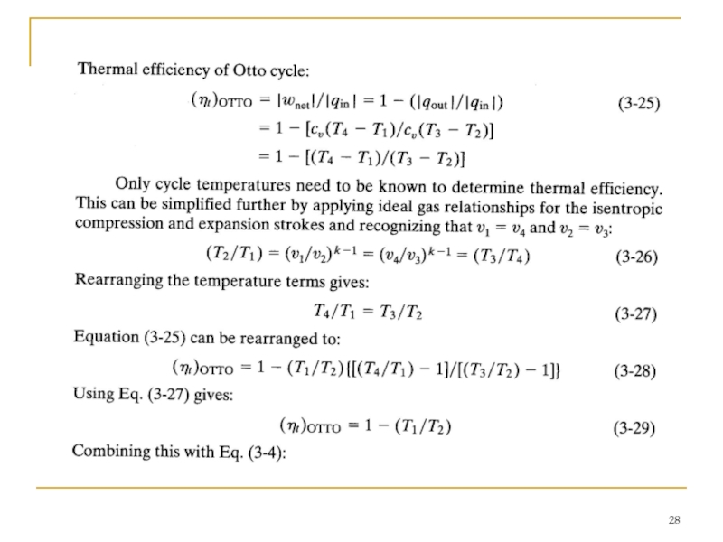
Indicated thermal efficiency of a real four-stroke SI engine is always somewhat less than what air-standard Otto cycle analysis predicts. This is caused by the heat losses, friction, ignition timing, valve timing, finite time of combustion and blowdown, and deviation from ideal gas behavior of the real engine. Reference shows that over a large range of operating variables the indicated thermal efficiency of an actual SI four-stroke cycle engine can be approximated by:
(T/t)actual = 0.85 (T/t)OTTO (3-32)
This will be correct to within a few percent for large ranges of air-fuel equivalence ratio, ignition timing, engine speed, compression ratio, inlet pressure, exhaust pressure, and valve timing.

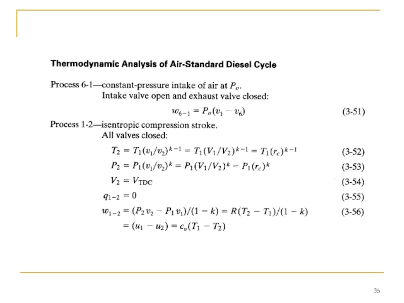
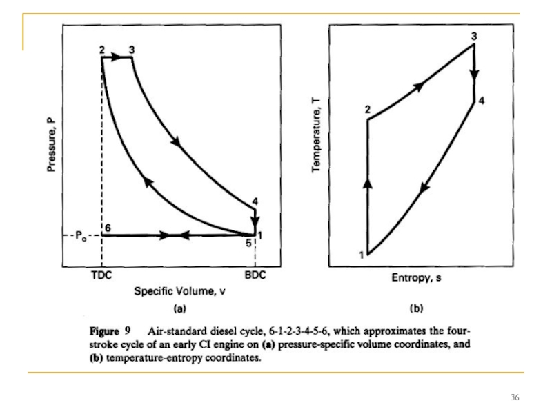
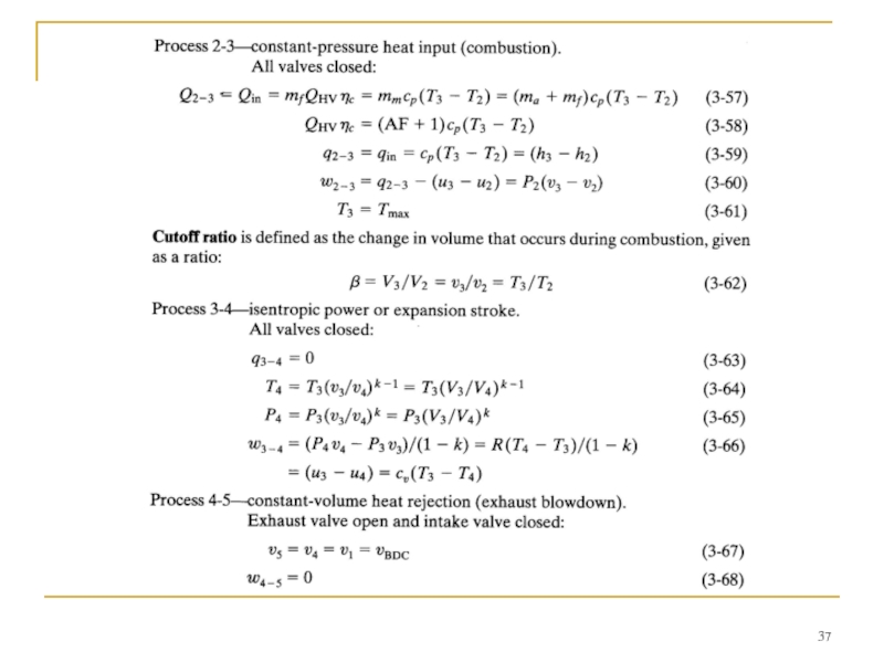
Слайд 34DIESEL CYCLE
This kept the pressure at peak levels well past TDC.
Early CI engines injected fuel into the combustion chamber very late in the compression stroke, resulting in the indicator diagram shown in Fig. 8. Due to ignition delay and the finite time required to inject the fuel, combustion lasted into the expansion stroke.


Слайд 39 If reptesentative numbers are introduced into Eq. (3-73), it is found
, it is found that the value of")

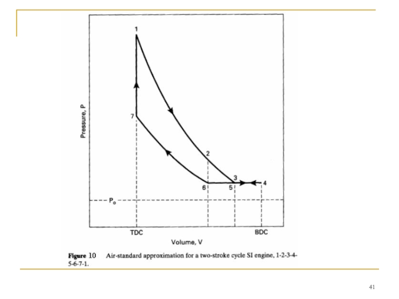
Слайд 42 Process 3-4-5-intake, and exhaust scavenging.
Exhaust port open and intake port open:
Intake
Process 5-6- exhaust scavenging.
Exhaust port open and intake port closed:
Exhaust scavenging continues until the exhaust port is closed at point 6.

Слайд 44TWO-STROKE CI ENGINE CYCLE
Many compression ignition engines-especially large ones-operate on two-stroke

Слайд 47SUMMARY
This chapter reviewed the basic cycles used in internal combustion engines.
Most small CI engines and very large CI engines operate on a two-stroke cycle. At present, most automobile engines operate on the four-stroke Otto cycle, but major research and development is resulting in two additional cycles for modem vehicles. Several companies have done major development work to try to create an automobile engine that would operate on an SI two-stroke cycle. Throughout history, two-stroke cycle automobile engines have periodically appeared with varying success. These offer greater power per unit weight, but none would pass modem emission standards. Recent development has concentrated on producing an engine that would satisfy pollution laws. The major technological change is the input of fuel by injection directly into the combustion chamber after exhaust and air intake are completed. If this development work is successful, there will be automobiles on the market with two-stroke cycle engines.