- Главная
- Разное
- Дизайн
- Бизнес и предпринимательство
- Аналитика
- Образование
- Развлечения
- Красота и здоровье
- Финансы
- Государство
- Путешествия
- Спорт
- Недвижимость
- Армия
- Графика
- Культурология
- Еда и кулинария
- Лингвистика
- Английский язык
- Астрономия
- Алгебра
- Биология
- География
- Детские презентации
- Информатика
- История
- Литература
- Маркетинг
- Математика
- Медицина
- Менеджмент
- Музыка
- МХК
- Немецкий язык
- ОБЖ
- Обществознание
- Окружающий мир
- Педагогика
- Русский язык
- Технология
- Физика
- Философия
- Химия
- Шаблоны, картинки для презентаций
- Экология
- Экономика
- Юриспруденция
Alternating Current motors презентация
Содержание
- 1. Alternating Current motors
- 2. Keywords Alternating Current motors – Двигатель переменного
- 3. Switched Reluctance Motor – коммутируемый реактивный электродвигатель,
- 4. ABBREVIATIONS BLAC - Brushless AC BLDC - Brushless DC
- 5. Сlassification AC motor
- 6. Electric drive with AC motors Slip
- 7. The relative velocity between the rotor and
- 8. A slip of 0 therefore indicates that
- 9. Rotor induced e.m.f., current and torque The
- 10. These relationships are shown in Figure Variation
- 11. Rotor currents and torque – small slip
- 12. This situation was assumed in the previous
- 13. To calculate the torque we
- 14. We don’t need to work
- 15. Provided that there are a large number
- 16. The torque–speed (and torque/slip) relationship for small
- 17. If the motor is unloaded, it will
- 18. Induction motors are usually designed so that
- 19. We note that, in this normal operating
- 20. Stator current-speed characteristics In the previous section,
- 21. The resultant stator current is the sum
- 22. Very high starting currents are one of
- 23. The torque and current axes are scaled
- 24. As the speed dropped, the motor torque
- 25. The speed therefore falls faster and faster,
- 26. Torque–speed curves – influence of rotor parameters
- 27. Types of AC drives Cage rotor For
- 28. So, we conclude that the low-resistance rotor
- 29. Altering the rotor resistance has little or
- 30. There are some applications for which high-resistance
- 31. To sum up, a high-rotor resistance is
- 32. Double cage rotors Double cage rotors have
- 33. The inner cage is sunk deep into
- 34. At the normal running speed the roles
- 35. Wound Rotor Motors Older motor designed to
- 36. Switched Reluctance Motor (SRM) The advantage of
- 37. Starting and run-up of slipring motors By
- 38. The influence of rotor resistance is shown
- 39. A high-rotor resistance is used when the
- 40. As the speed rises, the torque would
- 41. As mentioned earlier, the total energy dissipated
- 42. The resistance between the electrodes depends on
- 43. Different Methods of Speed Control of Three-Phase
- 44. Single-phase versions are used in small appliances.
- 47. But it is desirable to replace the
- 48. The benefit of improvement in the motor
- 49. Three phase induction machines are synchronous speed
- 50. They are comparatively less expensive to equivalent

Слайд 2Keywords
Alternating Current motors – Двигатель переменного тока
Squirrel cage motors – Двигатель
Wound rotor motors – Двигатель с фазным ротором
Slip – скольжение
electromotive force (e.m.f.) – ЭДС
rev/min - (no periods), revolutions per minute – об/мин
air-gap – воздушный зазор

Слайд 3Switched Reluctance Motor – коммутируемый реактивный электродвигатель, двигатель с регулируемым магнитным
p.u. (per unit) - относительные единицы
air-gap flux density - воздушный зазор плотности потока
maximum torque – критический момент
 -")
Слайд 4ABBREVIATIONS
BLAC - Brushless AC
BLDC - Brushless DC
BLDM - Brushless DC motor
EC - Electronic
PM - Permanent magnet
IPMSM - Interior permanent magnet synchronous motor
PMSM - Permanent magnet synchronous motor
SPMSM - Surface permanent magnet synchronous motor
SCIM - Squirrel-cage induction motor
SRM - Switched reluctance motor
SyRM - Synchronous reluctance motor
VFD - Variable-frequency drive
WRIM - Wound-rotor induction motor
WRSM - Wound-rotor synchronous motor


Слайд 6Electric drive with AC motors
Slip
A little thought will show that the

Слайд 7 The relative velocity between the rotor and the field is known
is the synchronous speed of the Weld, usually expressed in rev/min (revolutions per minute). The slip (as distinct from slip speed) is the normalised quantity defined by
and is usually expressed either as a ratio as in equation, or as a percentage.

Слайд 8 A slip of 0 therefore indicates that the rotor speed is

Слайд 9Rotor induced e.m.f., current and torque
The rate at which the rotor
The frequency of rotor e.m.f. is also directly proportional to slip, since the rotor effectively slides with respect to the flux wave, and the higher the relative speed, the more times in a second each rotor conductor is cut by a and a pole. At synchronous speed ( ) the frequency is zero, while at standstill ( ), the rotor frequency is equal to the supply frequency.

Слайд 10 These relationships are shown in Figure
Variation of rotor induced e.m.f and

Слайд 11Rotor currents and torque – small slip
When the slip is small
The current in each rotor conductor is therefore in time phase with the e.m.f. in that conductor, and the rotor current wave is therefore in space phase with the rotor e.m.f. wave, which in turn is in space phase with the flux wave.

Слайд 12 This situation was assumed in the previous discussion, and is represented
Pattern of air-gap flux density, induced e.m.f. and
current in cage rotor bars at low values of slip

Слайд 13 To calculate the torque we need to

Слайд 14
We don’t need to work out the torque in detail,
where and denote the amplitudes of the flux density wave and the rotor current wave, respectively.

Слайд 15 Provided that there are a large number of rotor bars (which
If the supply voltage and frequency are constant, the flux will be constant. The rotor e.m.f. (and hence ) is then proportional to slip, so we can see from equation that the torque is directly proportional to slip. We must remember that this discussion relates to low values of slip only, but since this is the normal running condition, it is extremely important.

Слайд 16 The torque–speed (and torque/slip) relationship for small slips is thus approximately
Torque–speed relationship for low values of slip
 relationship for small slips is thus approximately a straight-line, as shown")
Слайд 17 If the motor is unloaded, it will need very little torque
When the load is increased, the rotor slows down, and the slip increases, thereby inducing more rotor e.m.f. and current, and thus more torque. The speed will settle when the slip has increased to the point where the developed torque equals the load torque – for example point B in Figure

Слайд 18 Induction motors are usually designed so that their full-load torque is
The torque–slip (or torque–speed) characteristic shown in Figure is a good one for most applications, because the speed only falls a little when the load is raised from zero to its full value.

Слайд 19 We note that, in this normal operating region, the torque–speed curve
Family of steady-state torque–speed curves for a range
of armature voltages

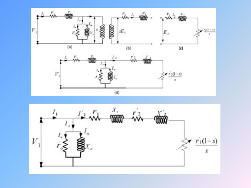
Слайд 20Stator current-speed characteristics
In the previous section, we argued that as the

Слайд 21 The resultant stator current is the sum of the magnetising current,

Слайд 22 Very high starting currents are one of the worst features of

Слайд 23 The torque and current axes are scaled so that 100% represents
We can check stability by asking what happens if the load torque suddenly changes for some reason. The load torque shown by the dotted line in Figure is stable at speed X, for example: if the load torque increased from Ta to Tb, the load torque would be greater than the motor torque, so the motor torque would decelerate.
")
Слайд 24 As the speed dropped, the motor torque would rise, until a
But what happens if the load torque is increased more and more? We can see that as the load torque increases, beginning at point X, we eventually reach point Z, at which the motor develops its maximum torque. Quite apart from the fact that the motor is now well into its overload region, and will be in danger of overheating, it has also reached the limit of stable operation. If the load torque is further increased, the speed falls (because the load torque is more than the motor torque), and as it does so the shortfall between motor torque and load torque becomes greater and greater.

Слайд 25 The speed therefore falls faster and faster, and the motor is

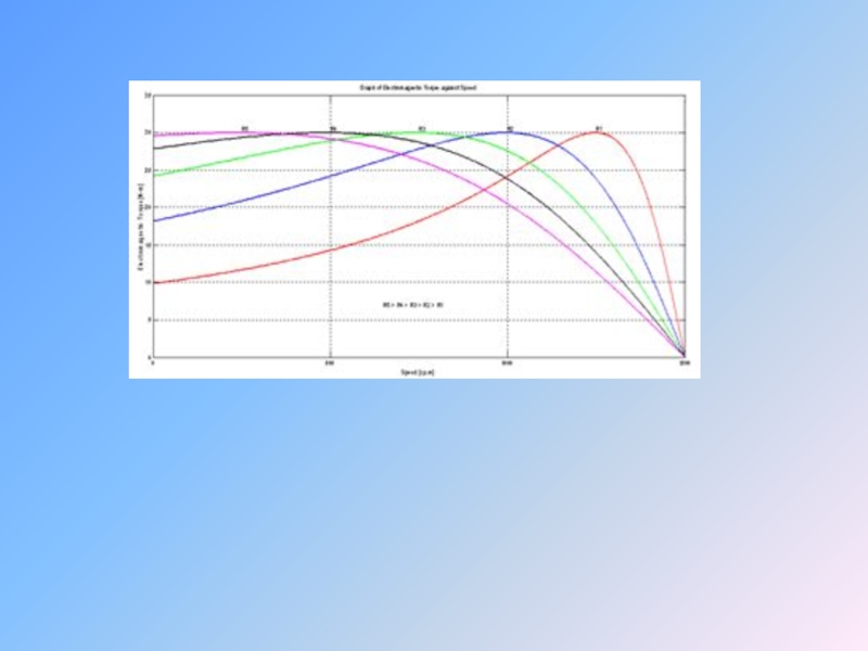
Слайд 26Torque–speed curves – influence of rotor parameters
We saw earlier that the
We will deal with the cage rotor first because it is the most important, but the wound rotor allows a wider variation of resistance to be obtained, so it is discussed later.

Слайд 27Types of AC drives
Cage rotor
For small values of slip, i.e. in

Слайд 28 So, we conclude that the low-resistance rotor not only gives better
As we might expect there are drawbacks with a low-resistance rotor. The starting torque is reduced (Figure), and worse still the starting current is increased. The lower starting torque may prove insufficient to accelerate the load, while increased starting current may lead to unacceptable volt drops in the supply.

Слайд 29 Altering the rotor resistance has little or no effect on the

Слайд 30 There are some applications for which high-resistance motors are well suited,

Слайд 31 To sum up, a high-rotor resistance is desirable when starting and

Слайд 32Double cage rotors
Double cage rotors have an outer cage made up
Alternative arrangements of double cage rotors
The outer cage has a high resistance (e.g. bronze) while the inner cage has a low resistance (e.g. copper).

Слайд 33 The inner cage is sunk deep into the rotor, so that

Слайд 34 At the normal running speed the roles are reversed. The rotor
Considerable variation in detailed design is possible to shape the torque–speed curve to particular requirements. In comparison with a single-cage rotor, the double cage gives much higher starting torque, substantially less starting current, and marginally worse running performance.

Слайд 35Wound Rotor Motors
Older motor designed to operate at “variable speed”
• Advantages
–
• Disadvantages
– Expensive, High Maintenance, Low Efficiency

Слайд 36Switched Reluctance Motor (SRM)
The advantage of a switched reluctance motor is
As with the ECM, electronics provide precisely timed voltages to the coils and use rotation position sensors for timing.
Switched Reluctance motors are used for several hundred thousand premium washing machines per year.
 The advantage of a switched reluctance motor is high torque at low")
Слайд 37Starting and run-up of slipring motors
By adding external resistance in series

Слайд 38 The influence of rotor resistance is shown by the set of

Слайд 39 A high-rotor resistance is used when the motor is first switched

Слайд 40 As the speed rises, the torque would fall more or less

Слайд 41 As mentioned earlier, the total energy dissipated in the rotor circuit
Fan-cooled grid resistors are often used, with tappings at various resistance values. These are progressively shorted-out during run-up, either by a manual or motor-driven drum-type controller, or with a series of timed contactors. Alternatively, where stepless variation of resistance is required, a liquid resistance controller is often employed. It consists of a tank of electrolyte (typically caustic soda) into which three electrodes can be raised or lowered.

Слайд 42 The resistance between the electrodes depends on how far they are
Attempts have been made to vary the effective rotor circuit resistance by means of a fixed external resistance and a set of series connected thyristors, but this approach has not gained wide acceptance.

Слайд 43Different Methods of Speed Control of Three-Phase Asynchronous Motor
An induction or

Слайд 44 Single-phase versions are used in small appliances. Their speed is determined

Слайд 47 But it is desirable to replace the single phase induction motor

Слайд 48 The benefit of improvement in the motor drive industry has touched

Слайд 49 Three phase induction machines are synchronous speed machines, operating below synchronous

Слайд 50 They are comparatively less expensive to equivalent size synchronous or dc