- Главная
- Разное
- Дизайн
- Бизнес и предпринимательство
- Аналитика
- Образование
- Развлечения
- Красота и здоровье
- Финансы
- Государство
- Путешествия
- Спорт
- Недвижимость
- Армия
- Графика
- Культурология
- Еда и кулинария
- Лингвистика
- Английский язык
- Астрономия
- Алгебра
- Биология
- География
- Детские презентации
- Информатика
- История
- Литература
- Маркетинг
- Математика
- Медицина
- Менеджмент
- Музыка
- МХК
- Немецкий язык
- ОБЖ
- Обществознание
- Окружающий мир
- Педагогика
- Русский язык
- Технология
- Физика
- Философия
- Химия
- Шаблоны, картинки для презентаций
- Экология
- Экономика
- Юриспруденция
Alternating current. (Lecture 3) презентация
Содержание
- 1. Alternating current. (Lecture 3)
- 2. Lecture 3 Alternating Current (AC) Inductors in
- 3. Alternating Current (AC) The voltage supplied by
- 4. Applying Kirchhoff’s loop, at any instant: The instantaneous current in the resistor is:
- 5. Where Imax is the maximum current:
- 6. Phasor Diagrams A phasor is a vector
- 7. Phasor diagram for a circuit with a
- 8. The projections of the phasor arrows onto
- 9. RMS
- 10. Because I2 varies as sin2 ωt
- 11. One reason we use rms values when
- 12. Inductors in AC Circuits Kirchhoff’s rule for
- 13. The maximal current in the inductor is
- 14. Phasor diagram for the inductive circuit,
- 15. Capacitors in AC The current is π/2
- 16. The maximal current is: The
- 17. Plot of the instantaneous current iC and
- 18. The RLC Series Circuit For convenience, and
- 19. The voltage across each element has a different amplitude and phase:
- 21. Impedance Using the previous calculations we can
- 23. Power in AC Circuit
- 24. Series RLC Circuit Resonance A series RLC
- 25. The average power dissipating in
- 26. Units in Si voltage (potential difference) V V (Volt)

Слайд 2Lecture 3
Alternating Current (AC)
Inductors in AC Circuits
Capacitors in AC Circuits
Series RLC
Impedance
Inductors in AC CircuitsCapacitors in AC CircuitsSeries RLC CircuitImpedance")
Слайд 3Alternating Current (AC)
The voltage supplied by an AC source is harmonic
AC source is designated by
The voltage supplied by an AC source is harmonic (sinusoidal) with a period")

Слайд 5
Where Imax is the maximum current:
And eventually:
Plots of the instantaneous current
So, for a sinusoidal applied voltage, the current in a resistor is always in phase with the voltage across the resistor.

Слайд 6Phasor Diagrams
A phasor is a vector whose length is proportional to

Слайд 7Phasor diagram for a circuit with a resistor is:
The phasor diagram

Слайд 8 The projections of the phasor arrows onto the vertical axis are


Слайд 10 Because I2 varies as sin2 ωt and because the average
Thus, the average power delivered to a resistor that carries an alternating current is
Alternating voltage is also best discussed in terms of rms voltage, and the relationship is identical to that for current:

Слайд 11 One reason we use rms values when discussing alternating currents and

Слайд 12Inductors in AC Circuits
Kirchhoff’s rule for AC circuit with an inductor
After derivation we get:
iL is the current through the inductor L.
For a sinusoidal applied voltage, the current in an inductor always lags behind the voltage across the inductor by 90° (one-quarter cycle in time).

Слайд 13 The maximal current in the inductor is
We can define the inductive
The instantaneous voltage across the inductor is:

Слайд 14 Phasor diagram for the inductive circuit, showing that the current
Phasor diagram for the inductive circuit, showing that the current lags behind the voltage by 90°.

Слайд 15Capacitors in AC
The current is π/2 rad = 90° out of
For a sinusoidally applied voltage, the current always leads the voltage across a capacitor by 90°.

Слайд 16 The maximal current is:
The capacitive reactance of the capacitor to the
Then the instantaneous voltage across the capacitor is:

Слайд 17 Plot of the instantaneous current iC and instantaneous voltage ΔVC across
Phasor diagram for the capacitive circuit, showing that the current leads the voltage by 90°.

Слайд 18The RLC Series Circuit
For convenience, and not losing generalization, we can
and the current is
Where φ=const is some phase angle between the current and the applied voltage. Because the elements are in series, the current everywhere in the circuit must be the same at any instant. That is, the current at all points in a series AC circuit has the same amplitude and phase.


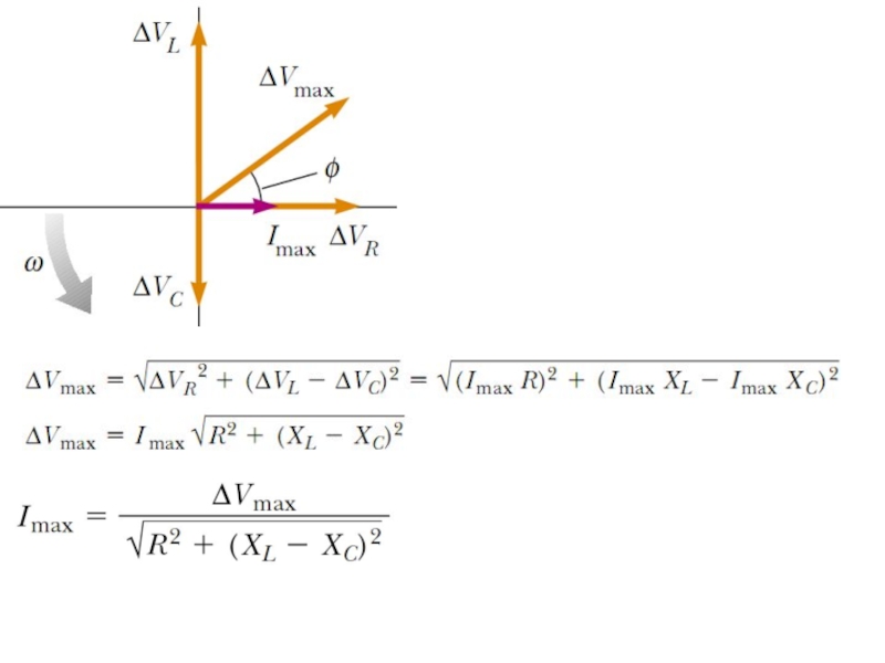
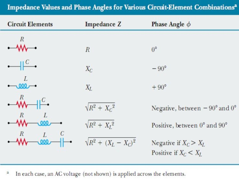
Слайд 21Impedance
Using the previous calculations we can define a new parameter impedance:
So,
Using the phasor diagram:

Слайд 23Power in AC Circuit
The average power delivered by the source is
No power losses are associated with pure capacitors and pure inductors in an AC circuit.

Слайд 24Series RLC Circuit Resonance
A series RLC circuit is in resonance when
So resonance is at XL=XC, the frequency ω0 when XL=XC is called the resonance frequency:
This frequency corresponds to the natural frequency of oscillation of an LC circuit

Слайд 25
The average power dissipating in the resistor is
Then at resonance the

Слайд 26Units in Si
voltage (potential difference) V V (Volt)
current (electric current) I A (Ampere)
inductance L H (Henry)
inductive reactance XL Ω
capacitive reactance XC Ω (Ohm)
Impedance Z Ω (Ohm)
Power P W (Watt)
 V V (Volt)current (electric current) I A (Ampere)inductance L H (Henry)inductive reactance XL Ω (Ohm)capacitive reactance XC Ω (Ohm)Impedance Z Ω (Ohm)Power P W (Watt)")