- Главная
- Разное
- Дизайн
- Бизнес и предпринимательство
- Аналитика
- Образование
- Развлечения
- Красота и здоровье
- Финансы
- Государство
- Путешествия
- Спорт
- Недвижимость
- Армия
- Графика
- Культурология
- Еда и кулинария
- Лингвистика
- Английский язык
- Астрономия
- Алгебра
- Биология
- География
- Детские презентации
- Информатика
- История
- Литература
- Маркетинг
- Математика
- Медицина
- Менеджмент
- Музыка
- МХК
- Немецкий язык
- ОБЖ
- Обществознание
- Окружающий мир
- Педагогика
- Русский язык
- Технология
- Физика
- Философия
- Химия
- Шаблоны, картинки для презентаций
- Экология
- Экономика
- Юриспруденция
Introduction. Waste management презентация
Содержание
- 1. Introduction. Waste management
- 2. Waste management Waste management includes the
- 3. Waste Policy in Finland Is in line
- 4. The 4 R concept The 4R
- 5. Practising the 4 R concept Reducing waste
- 6. Lecture 2: Collection and transport
- 7. 8.9.2016 Waste management and recycling - Collection
- 8. 8.9.2016 Waste management and recycling - Collection
- 9. 8.9.2016 Waste management and recycling - Collection
- 10. 8.9.2016 Waste management and recycling - Collection
- 11. 8.9.2016 Waste management and recycling - Collection
- 12. 8.9.2016 Waste management and recycling - Collection
- 13. 8.9.2016 Waste management and recycling - Collection
- 14. 8.9.2016 Waste management and recycling - Collection
- 15. 8.9.2016 Waste management and recycling - Collection
- 16. 8.9.2016 Waste management and recycling - Collection
- 17. 8.9.2016 Waste management and recycling - Collection and transport Waste collection trucks for option C
- 18. 8.9.2016 Waste management and recycling - Collection and transport Logistics and transport routes
- 19. 8.9.2016 Waste management and recycling - Collection
- 20. Lecture 3: Waste sorting
- 21. 8.9.2016 Waste management and recycling - Sorting
- 22. 8.9.2016 Waste management and recycling - Sorting
- 23. 8.9.2016 Waste management and recycling - Sorting
- 24. 8.9.2016 Waste management and recycling - Sorting
- 25. 8.9.2016 Waste management and recycling - Sorting
- 26. 8.9.2016 Waste management and recycling - Sorting
- 27. 8.9.2016 Waste management and recycling - Sorting
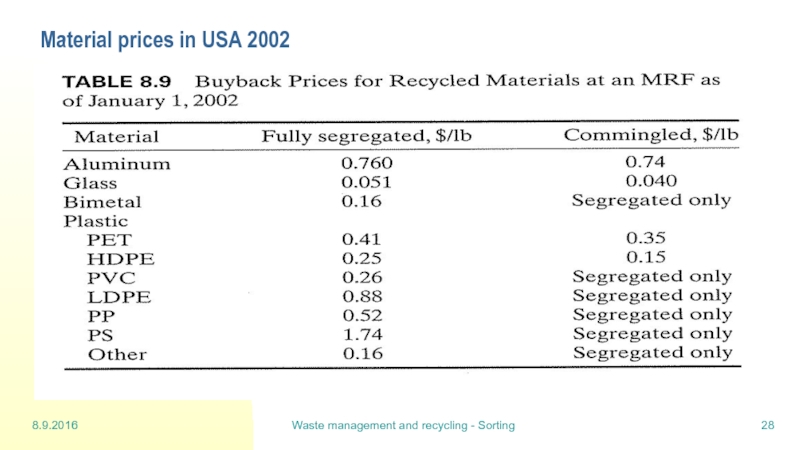
- 28. 8.9.2016 Waste management and recycling - Sorting Material prices in USA 2002
- 29. 8.9.2016 Waste management and recycling - Sorting
- 30. 8.9.2016 Waste management and recycling - Sorting
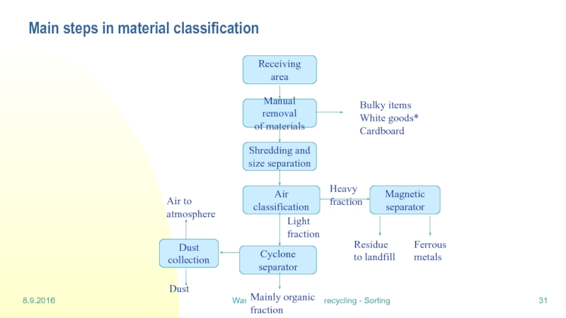
- 31. 8.9.2016 Waste management and recycling - Sorting Main steps in material classification
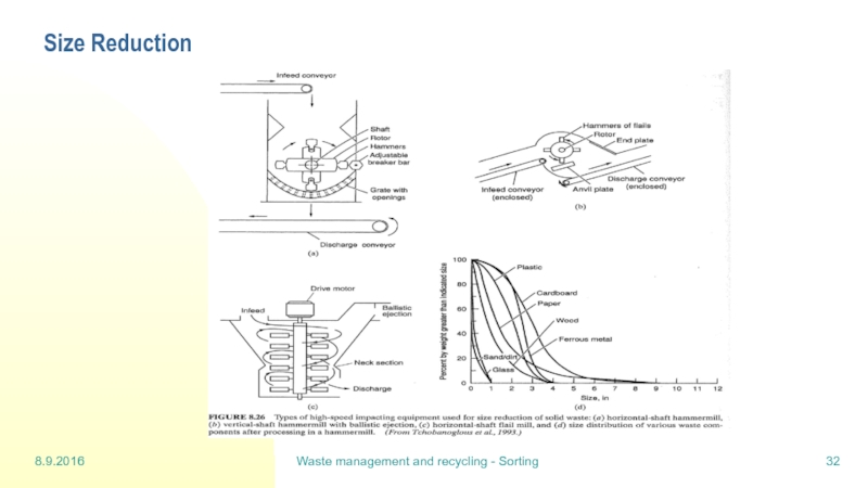
- 32. 8.9.2016 Waste management and recycling - Sorting Size Reduction
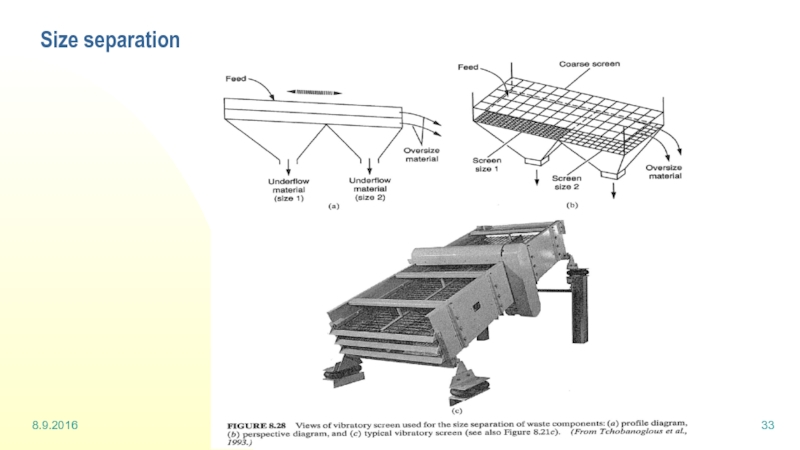
- 33. 8.9.2016 Waste management and recycling - Sorting Size separation
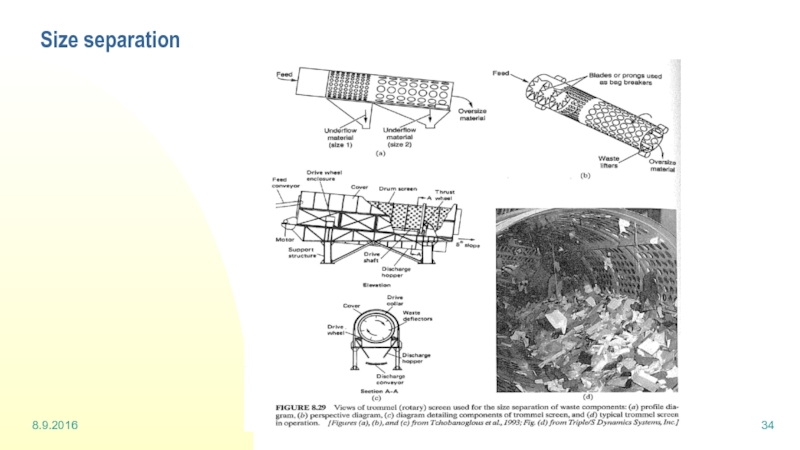
- 34. 8.9.2016 Waste management and recycling - Sorting Size separation
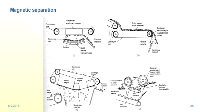
- 35. 8.9.2016 Waste management and recycling - Sorting Magnetic separation
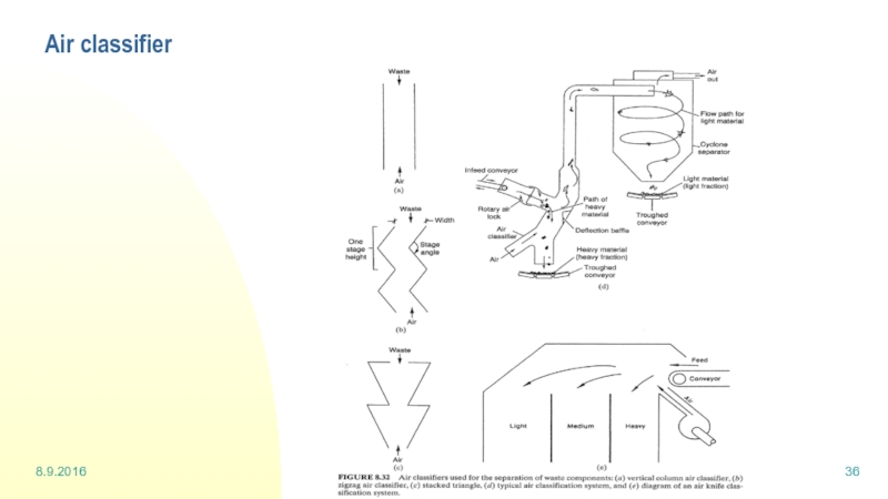
- 36. 8.9.2016 Waste management and recycling - Sorting Air classifier
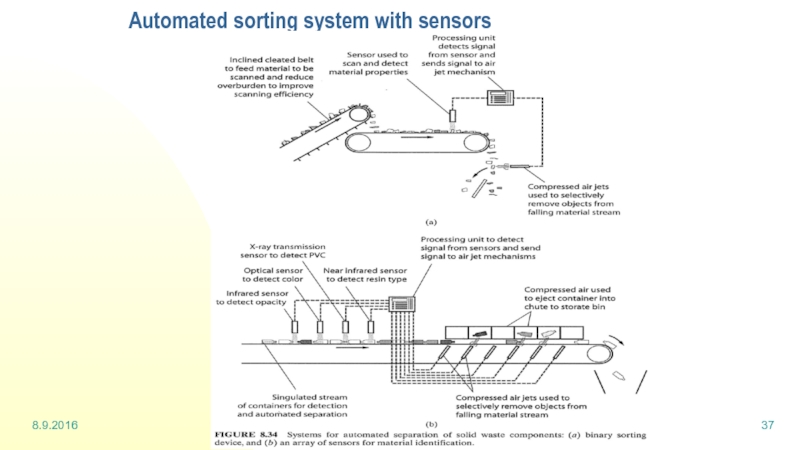
- 37. 8.9.2016 Waste management and recycling - Sorting Automated sorting system with sensors
- 38. Lecture 4: Landfill
- 39. 22.9.2016 Waste management and recycling - Landfill
- 40. 22.9.2016 Waste management and recycling - Landfill
- 41. 22.9.2016 Waste management and recycling - Landfill
- 42. 22.9.2016 Waste management and recycling - Landfill
- 43. 22.9.2016 Waste management and recycling - Landfill
- 44. 22.9.2016 Waste management and recycling - Landfill
- 45. 22.9.2016 Waste management and recycling - Landfill
- 46. 22.9.2016 Waste management and recycling - Landfill
- 47. 22.9.2016 Waste management and recycling - Landfill
- 48. 22.9.2016 Waste management and recycling - Landfill
- 49. 22.9.2016 Waste management and recycling - Landfill
- 50. 22.9.2016 Waste management and recycling - Landfill
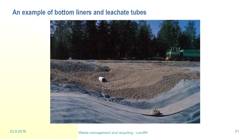
- 51. 22.9.2016 Waste management and recycling - Landfill An example of bottom liners and leachate tubes
- 52. Lecture 5: Composting (part 1)
- 53. 29.9.2016 Waste management and recycling - Composting
- 54. 29.9.2016 Waste management and recycling - Composting
- 55. 29.9.2016 Waste management and recycling - Composting
- 56. 29.9.2016 Waste management and recycling - Composting
- 57. 29.9.2016 Waste management and recycling - Composting
- 58. 29.9.2016 Waste management and recycling - Composting
- 59. 29.9.2016 Waste management and recycling - Composting
- 60. 29.9.2016 Waste management and recycling - Composting
- 61. 29.9.2016 Waste management and recycling - Composting
- 62. 29.9.2016 Waste management and recycling - Composting
- 63. 29.9.2016 Waste management and recycling - Composting
- 64. Lecture 6: Digestion
- 65. 6.10.2016 Waste management and recycling - Digestion
- 66. 6.10.2016 Waste management and recycling - Digestion
- 67. 6.10.2016 Waste management and recycling - Digestion
- 68. 6.10.2016 Waste management and recycling - Digestion
- 69. 6.10.2016 Waste management and recycling - Digestion
- 70. 6.10.2016 Waste management and recycling - Digestion
- 71. Lecture 7: Waste incineration (part 2)
- 72. 13.10.2016 Waste management and recycling - incineration
- 73. 13.10.2016 Waste management and recycling - incineration
- 74. 13.10.2016 Waste management and recycling - incineration
- 75. 13.10.2016 Waste management and recycling - incineration
- 76. 13.10.2016 Waste management and recycling - incineration
- 77. 13.10.2016 Waste management and recycling - incineration
- 78. 13.10.2016 Waste management and recycling - incineration
- 79. 13.10.2016 Waste management and recycling - incineration
- 80. 13.10.2016 Waste management and recycling - incineration
- 81. 13.10.2016 Waste management and recycling - incineration
- 82. 13.10.2016 Waste management and recycling - incineration
- 83. 13.10.2016 Waste management and recycling - incineration
- 84. 13.10.2016 Waste management and recycling - incineration
- 85. 13.10.2016 Waste management and recycling - incineration
- 86. 13.10.2016 Waste management and recycling - incineration
- 87. 13.10.2016 Waste management and recycling - incineration
- 88. 13.10.2016 Waste management and recycling - incineration
- 89. 13.10.2016 Waste management and recycling - incineration
- 90. 13.10.2016 Waste management and recycling - incineration
- 91. 13.10.2016 Waste management and recycling - incineration
- 92. Lecture 8: Hazardous waste
- 93. 20.10.2016 Waste management and recycling - Hazardous
- 94. Types of hazardous waste Solid wastes Liquid
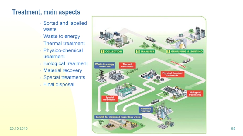
- 95. Treatment, main aspects Sorted and labelled waste
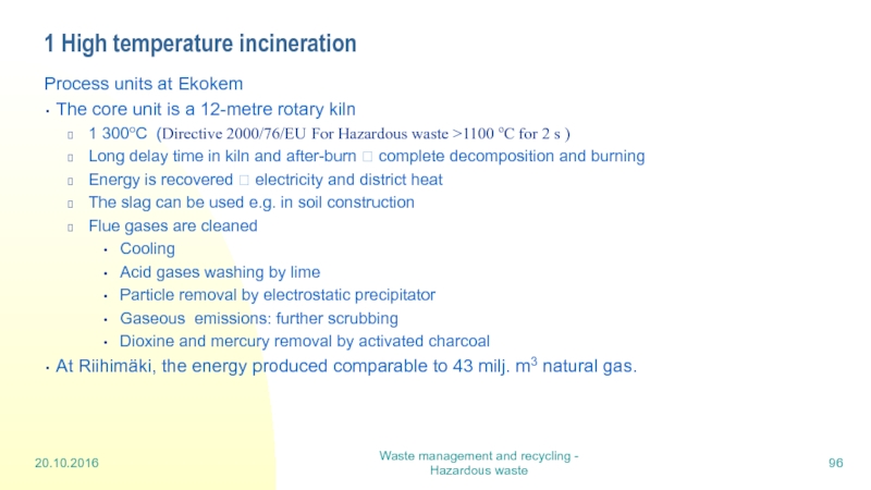
- 96. 1 High temperature incineration Process units at
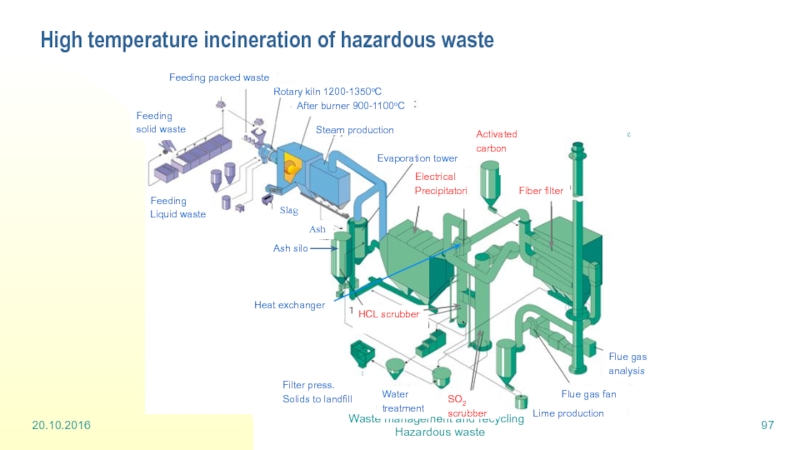
- 97. High temperature incineration of hazardous waste
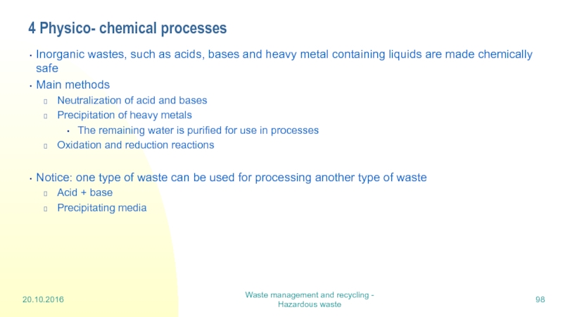
- 98. 4 Physico- chemical processes Inorganic wastes, such
- 99. Physico-chemical processes 20.10.2016 Waste management and recycling
- 100. Lecture 9: Life cycle assessment
- 101. Waste management and recycling - LCA 10
- 102. Waste management and recycling - LCA Life
- 103. Waste management and recycling - LCA LCA,
- 104. Waste management and recycling - LCA Unit
- 105. Waste management and recycling - LCA A
- 106. Waste management and recycling - LCA Different
- 107. Waste management and recycling - LCA Impact
- 108. Waste management and recycling - LCA Impact
- 109. Waste management and recycling - LCA Impact
Слайд 2Waste management
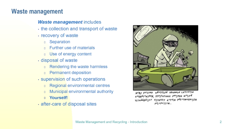
Waste management includes
the collection and transport of waste
recovery of
Separation
Further use of materials
Use of energy content
disposal of waste
Rendering the waste harmless
Permanent deposition
supervision of such operations
Regional environmental centres
Municipal environmental authority
Yourself!
after-care of disposal sites
Waste Management and Recycling - Introduction
Слайд 3Waste Policy in Finland
Is in line with the EU waste policy
Sets
Prevention: The production and harmful impacts of wastes should be reduced and wherever possible prevented at source.
The Polluter Pays: The producers of wastes take responsibility for the costs of waste management.
Producer Responsibility: Manufacturers and importers of certain product types must bear the responsibility for the management of their products when they become wastes, instead of waste producers.
The Precautionary Principle: Potential problems related to wastes and waste management should be anticipated and avoided.
The Proximity Principle: Wastes should be disposed of near to their source.
The Self-sufficiency Principle: The EU and member states should remain self-sufficient with regard to the disposal of wastes.
Waste Management and Recycling - Introduction
Слайд 4The 4 R concept
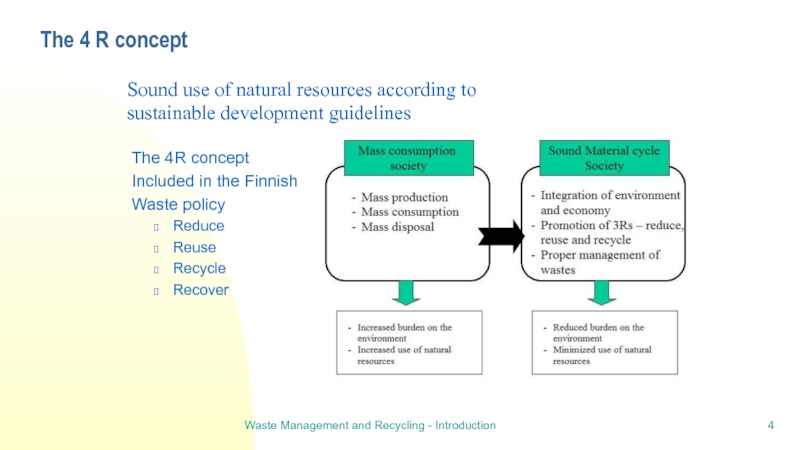
The 4R concept
Included in the Finnish
Waste policy
Reduce
Reuse
Recycle
Recover
Sound use of natural resources according to
sustainable development guidelines
Waste Management and Recycling - Introduction
Слайд 5Practising the 4 R concept
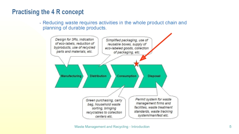
Reducing waste requires activities in the whole
Waste Management and Recycling - Introduction
Слайд 78.9.2016
Waste management and recycling - Collection and transport
Practises in Household Waste
Waste collection is organised by:
Waste producer or property holder (Finnish Waste Act, Section 7)
Garden waste, food waste and toilet waste can be composted on the property
rules how to do it
Information to be given to the authority
Waste transport
Waste holder shall take care that transport is organised (WA, section 8)
Waste transporter has to take the waste to a facility specified by waste holder or authority (WA, section 9)
Municipality is responsible for organising waste transport (WA, section 10)
for all household wastes including septic tank and cesspit sludges
for enterprise wastes comparable to household wastes, if situated on a housing property
for public operators
Transport organised by municipality itself, or using services of a company
Waste transport scheme = systems and activities organised by a municipality for waste transport. Waste holder shall subscribe to waste transport scheme.
Слайд 88.9.2016
Waste management and recycling - Collection and transport
Waste Act
Municipal waste management
Municipalities can issue local general regulations on more detailed
implementation of the provisions of Ch.3 in WA and of Government
general regulations issued under them.
Regulations may concern:
1) waste collection, sorting, storage, transport, dealing, recovery or disposal and the technical requirements for them
2) measures required to prevent hazard or harm to health or the environment
3) supervision of waste management.
Goverment can issue general regulations concerning waste management
implementation (WA section 18)
Слайд 98.9.2016
Waste management and recycling - Collection and transport
Municipal waste management in
Mikkeli and neighbouring municipalities founded a company (Metsä-Sairila) to
organise waste management
Metsä-Sairila is responsible for all tasks of municipalities in waste management
excluding
Authority tasks like acceptance of local regulations and charges (payments)
Authority decisions
Responsibilities of Metsä-Sairila
Recycling
Hazardous wastes
Composting of separately collected bio waste and sludge
Planning, developing, coordination and information
Also treatment facilities; enlargement ; after care of landfill site.
Слайд 108.9.2016
Waste management and recycling - Collection and transport
How waste management is
Waste transport schemes for household wastes and similar other wastes:
In densely populated area: Property owner makes an agreement with waste
transporter (contractual waste transport scheme)
Sparsely populated area: Subscribing to waste transport scheme (announcement
to Metsä-Sairila)
Possibilities
Waste collection sites.
About 60 in the region. Annual charges.
Collection at the property
Agreement with a waste transporter
Forbidden to use of collection sites
Two or more properties may combine their efforts and share a waste bin
Слайд 118.9.2016
Waste management and recycling - Collection and transport
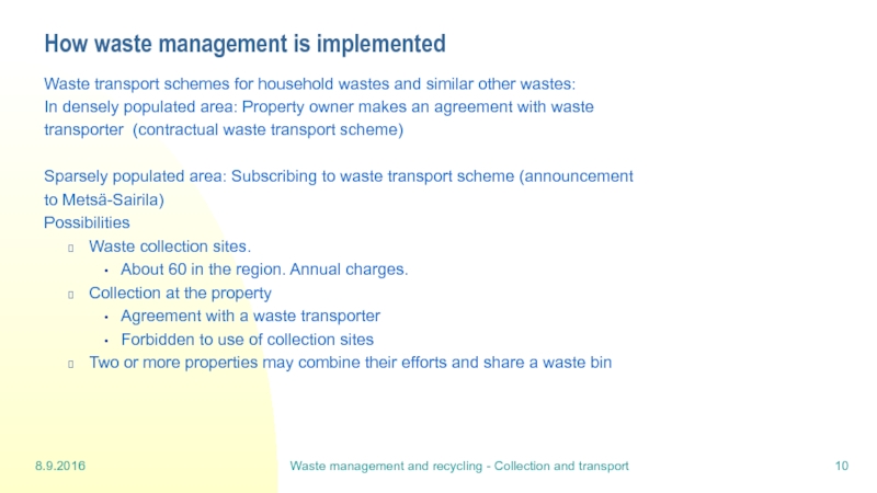
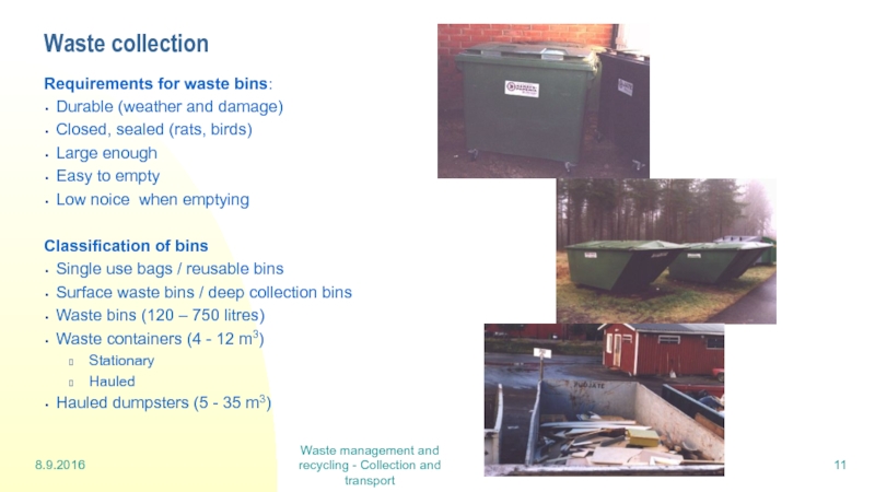
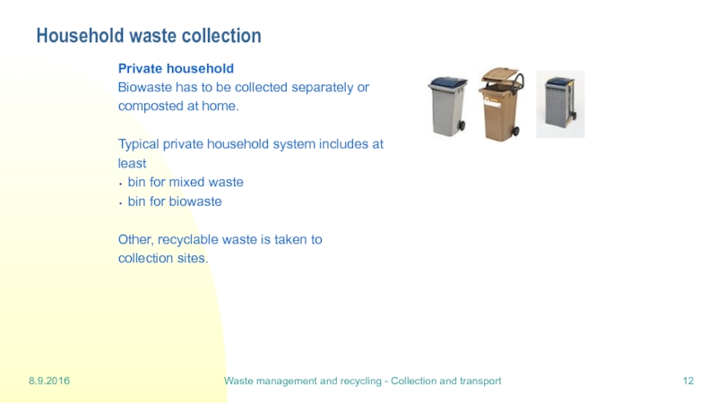
Waste collection
Requirements for waste
Durable (weather and damage)
Closed, sealed (rats, birds)
Large enough
Easy to empty
Low noice when emptying
Classification of bins
Single use bags / reusable bins
Surface waste bins / deep collection bins
Waste bins (120 – 750 litres)
Waste containers (4 - 12 m3)
Stationary
Hauled
Hauled dumpsters (5 - 35 m3)
Слайд 128.9.2016
Waste management and recycling - Collection and transport
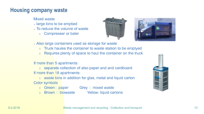
Household waste collection
Private household
Biowaste
composted at home.
Typical private household system includes at
least
bin for mixed waste
bin for biowaste
Other, recyclable waste is taken to
collection sites.
Слайд 138.9.2016
Waste management and recycling - Collection and transport
Housing company waste
Mixed
large bins to be emptied
To reduce the volume of waste
Compresser or baler
Also large containers used as storage for waste
Truck haules the container to waste station to be emptyed
Requires plenty of space to haul the container on the truck
If more than 5 apartments:
separate collection of also paper and and cardboard
If more than 18 apartments:
waste bins in addition for glas, metal and liquid carton
Color symbols
Green? paper Grey ? mixed waste
Brown ? biowaste Yellow: liquid cartons
Слайд 148.9.2016
Waste management and recycling - Collection and transport
Public waste collection sites
Waste
Amount of waste is high
Emptying is done seldom
Necessary to
Have large bins
Moderate temperatures around the year
Odor has to be prevented
Typical places eg.
Remote places
Recreation areas
Parking/resting areas
Public buildings (schools…)
Слайд 158.9.2016
Waste management and recycling - Collection and transport
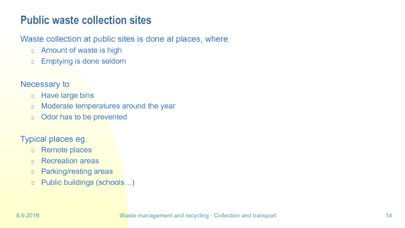
Public waste collection sites
Modern
bins (MOLOK)
Most of the structure is hidden in the ground
The wastes are in a bag that is lifted up and emptied into a truck
Benefits
Small space demand
Emptying is easy
less space demanding
Possible even by boat
Hygienic for biowaste – temperature stays low even in summer
Quite fire safe
Слайд 168.9.2016
Waste management and recycling - Collection and transport
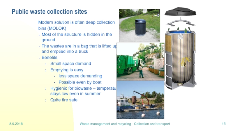
Logistics in waste transport
The
The collection system depends on the equipment.
Слайд 178.9.2016
Waste management and recycling - Collection and transport
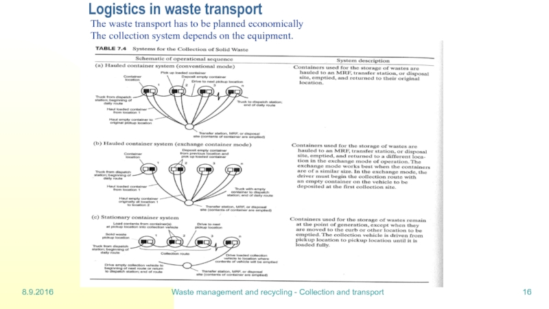
Waste collection trucks for
Слайд 188.9.2016
Waste management and recycling - Collection and transport
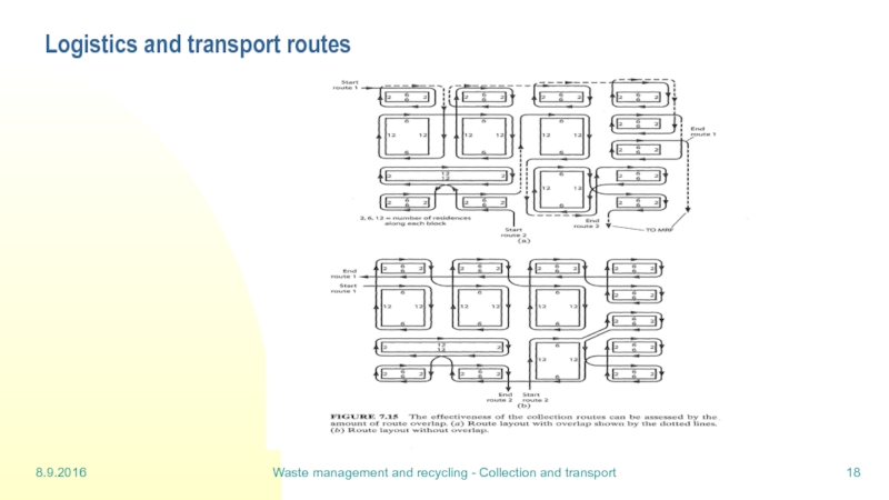
Logistics and transport routes
Слайд 198.9.2016
Waste management and recycling - Collection and transport
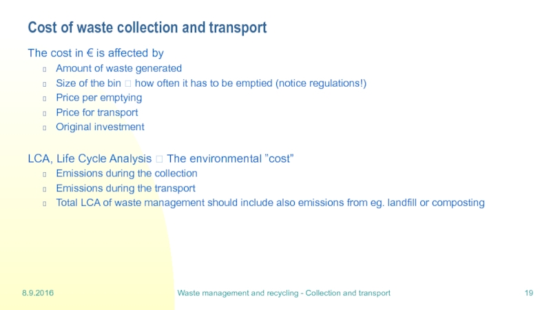
Cost of waste collection
The cost in € is affected by
Amount of waste generated
Size of the bin ? how often it has to be emptied (notice regulations!)
Price per emptying
Price for transport
Original investment
LCA, Life Cycle Analysis ? The environmental ”cost”
Emissions during the collection
Emissions during the transport
Total LCA of waste management should include also emissions from eg. landfill or composting
Слайд 218.9.2016
Waste management and recycling - Sorting
Waste types
Waste should be sorted for
In Finland sorting is done basicly at source
In many countries mechanical sorting stations
Waste to landfill should not contain any reusable, recyclable, recoverable
waste or hazardous waste or organic carbon that may result greenhouse gas emissions:
Biowaste
Paper, cardboard
Glass, metal, electrical waste
Wood, plastics….
Mixed municipal waste (MMW) quality
Depends on single waste producers
Contains also hazardous waste from households
Landfills are often situated by waste centres where all kinds of waste are
recepted for further treatment or transfer
Слайд 228.9.2016
Waste management and recycling - Sorting
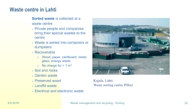
Waste centre in Lahti
Sorted waste is
waste centre
Private people and companies bring their special wastes to the centre
Waste is sorted into containers or dumpsters
Recoverable
Wood, paper, cardboard, metal, glass, energy waste
No charge for < 1 m3
Soil and rocks
Garden waste
Preserved wood
Landfill waste
Electrical and electronic waste
Kujala, Lahti
Waste sorting centre Pilleri
Слайд 238.9.2016
Waste management and recycling - Sorting
Recyclable materials sorted at source
Waste
facilities
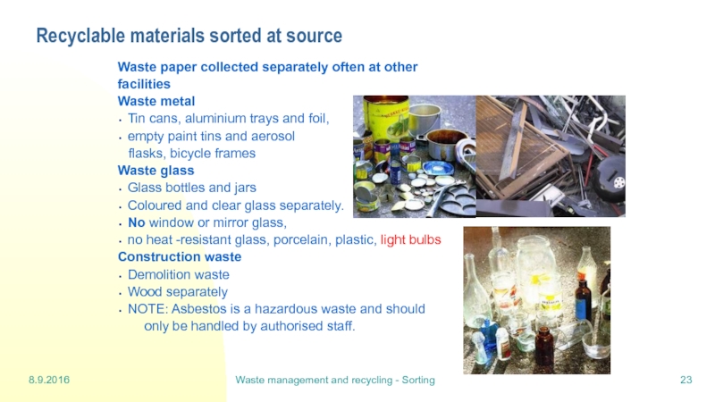
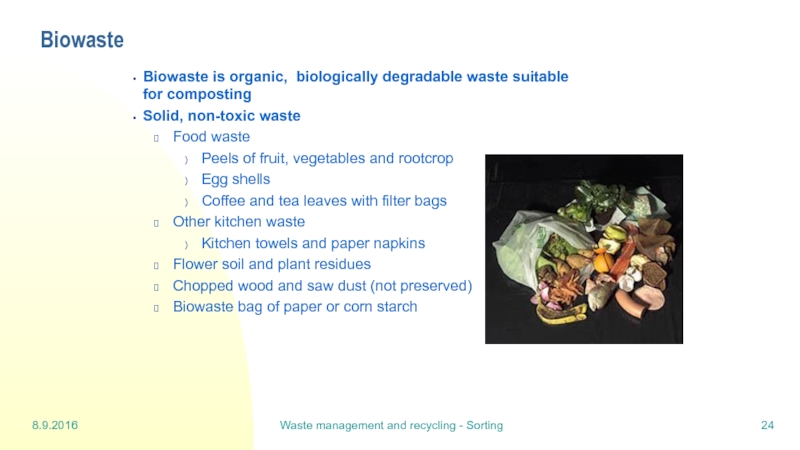
Waste metal
Tin cans, aluminium trays and foil,
empty paint tins and aerosol
flasks, bicycle frames
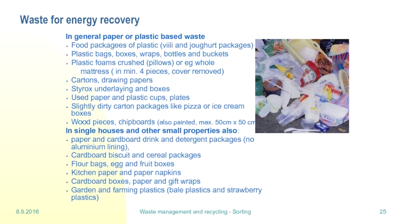
Waste glass
Glass bottles and jars
Coloured and clear glass separately.
No window or mirror glass,
no heat -resistant glass, porcelain, plastic, light bulbs
Construction waste
Demolition waste
Wood separately
NOTE: Asbestos is a hazardous waste and should
only be handled by authorised staff.
Слайд 248.9.2016
Waste management and recycling - Sorting
Biowaste
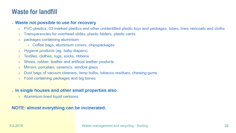
Biowaste is organic, biologically degradable waste
Solid, non-toxic waste
Food waste
Peels of fruit, vegetables and rootcrop
Egg shells
Coffee and tea leaves with filter bags
Other kitchen waste
Kitchen towels and paper napkins
Flower soil and plant residues
Chopped wood and saw dust (not preserved)
Biowaste bag of paper or corn starch
Слайд 258.9.2016
Waste management and recycling - Sorting
Waste for energy recovery
In general paper
Food packagees of plastic (viili and joughurt packages)
Plastic bags, boxes, wraps, bottles and buckets
Plastic foams crushed (pillows) or eg whole
mattress ( in min. 4 pieces, cover removed)
Cartons, drawing papers
Styrox underlaying and boxes
Used paper and plastic cups, plates
Slightly dirty carton packages like pizza or ice cream boxes
Wood pieces, chipboards (also painted, max. 50cm x 50 cm)
In single houses and other small properties also:
paper and cardboard drink and detergent packages (no aluminium lining),
Cardboard biscuit and cereal packages
Flour bags, egg and fruit boxes
Kitchen paper and paper napkins
Cardboard boxes, paper and gift wraps
Garden and farming plastics (bale plastics and strawberry plastics)
Слайд 268.9.2016
Waste management and recycling - Sorting
Waste for landfill
Waste not possible to
PVC-plastics, 03-marked plastics and other unidentified plastic toys and packages, tubes, lines raincoats and cloths
Transparencies for overhead slides, plastic folders, plastic cards
packages containing aluminium
Coffee bags, aluminium covers, chipspackages
Hygiene products (eg. baby diapers)
Textiles: clothes, rugs, socks, ribbons
Shoes, rubber, leather and artificial leather products
Mirrors, porcelain, ceramics, window glass
Dust bags of vacuum cleaners, lamp bulbs, tobacco residues, chewing gums
Food containing packages and big bones
In single houses and other small properties also:
Aluminium lined liquid cartoons
NOTE: almost everything can be incinerated.
Слайд 278.9.2016
Waste management and recycling - Sorting
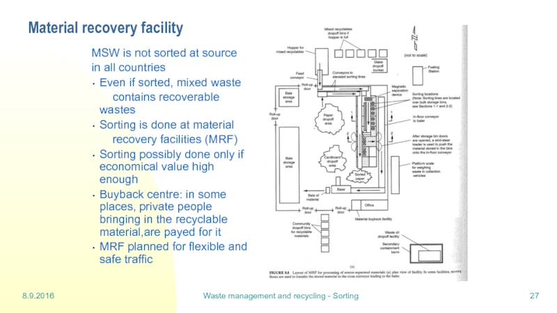
Material recovery facility
MSW is not sorted
in all countries
Even if sorted, mixed waste
contains recoverable wastes
Sorting is done at material
recovery facilities (MRF)
Sorting possibly done only if economical value high enough
Buyback centre: in some places, private people bringing in the recyclable material,are payed for it
MRF planned for flexible and safe traffic
Слайд 298.9.2016
Waste management and recycling - Sorting
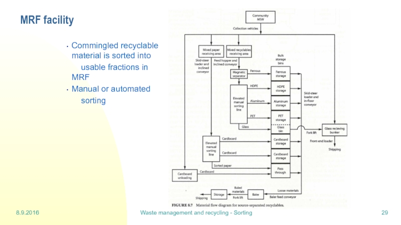
MRF facility
Commingled recyclable material is sorted
usable fractions in MRF
Manual or automated
sorting
Слайд 308.9.2016
Waste management and recycling - Sorting
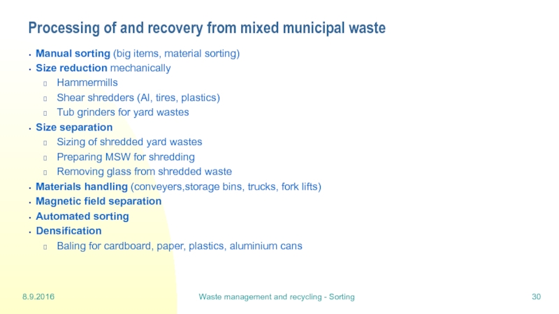
Processing of and recovery from mixed
Manual sorting (big items, material sorting)
Size reduction mechanically
Hammermills
Shear shredders (Al, tires, plastics)
Tub grinders for yard wastes
Size separation
Sizing of shredded yard wastes
Preparing MSW for shredding
Removing glass from shredded waste
Materials handling (conveyers,storage bins, trucks, fork lifts)
Magnetic field separation
Automated sorting
Densification
Baling for cardboard, paper, plastics, aluminium cans
Слайд 3922.9.2016
Waste management and recycling - Landfill
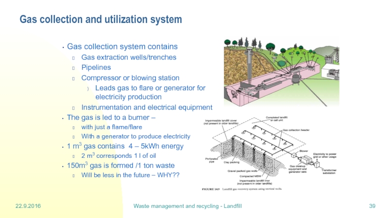
Gas collection and utilization system
Gas collection
Gas extraction wells/trenches
Pipelines
Compressor or blowing station
Leads gas to flare or generator for electricity production
Instrumentation and electrical equipment
The gas is led to a burner –
with just a flame/flare
With a generator to produce electricity
1 m3 gas contains 4 – 5kWh energy
2 m3 corresponds 1 l of oil
150m3 gas is formed /1 ton waste
Will be less in the future – WHY??
Слайд 4022.9.2016
Waste management and recycling - Landfill
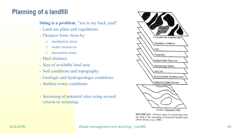
Planning of a landfill
Siting is a
Land use plans and regulations
Distance form close-by
residential areas
water resources
recreation areas
Haul distance
Size of available land area
Soil conditions and topography
Geologic and hydrogeologic conditions
Surface-water conditions
Screening of potential sites using several criteria in screening
Слайд 4122.9.2016
Waste management and recycling - Landfill
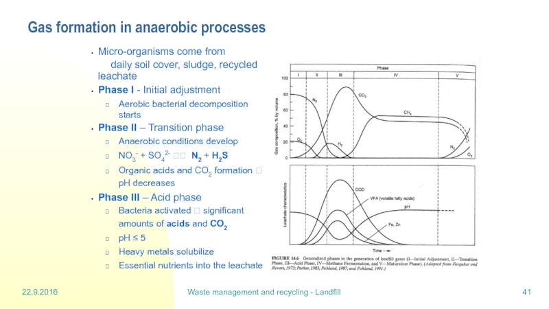
Gas formation in anaerobic processes
Micro-organisms come
daily soil cover, sludge, recycled leachate
Phase I - Initial adjustment
Aerobic bacterial decomposition starts
Phase II – Transition phase
Anaerobic conditions develop
NO3- + SO42- ?? N2 + H2S
Organic acids and CO2 formation ? pH decreases
Phase III – Acid phase
Bacteria activated ? significant amounts of acids and CO2
pH ≤ 5
Heavy metals solubilize
Essential nutrients into the leachate
Слайд 4222.9.2016
Waste management and recycling - Landfill
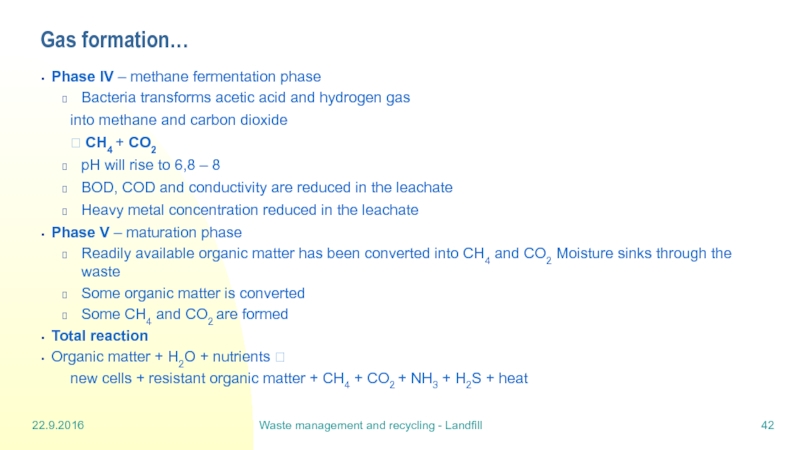
Gas formation…
Phase IV – methane fermentation
Bacteria transforms acetic acid and hydrogen gas
into methane and carbon dioxide
? CH4 + CO2
pH will rise to 6,8 – 8
BOD, COD and conductivity are reduced in the leachate
Heavy metal concentration reduced in the leachate
Phase V – maturation phase
Readily available organic matter has been converted into CH4 and CO2 Moisture sinks through the waste
Some organic matter is converted
Some CH4 and CO2 are formed
Total reaction
Organic matter + H2O + nutrients ?
new cells + resistant organic matter + CH4 + CO2 + NH3 + H2S + heat
Слайд 4322.9.2016
Waste management and recycling - Landfill
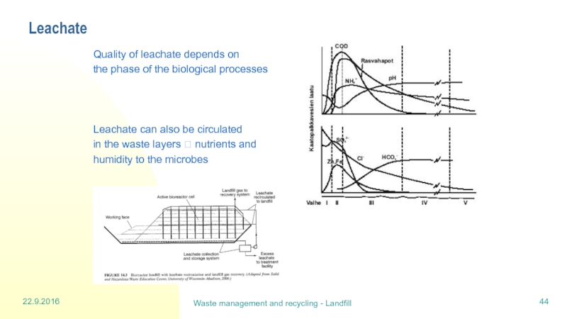
Formation of leachate
Amount of leachate varies
Average amount is 7 – 16 m3 /ha*d
In a closed, well covered landfill 3-4 m3/ha*d
Volume can be reduced by
Plants growing on closed parts of a landfill
Willow 20-30%, grass 5-20%
Watering the surface of the landfill (evaporation)
The leachate contains
Biodegradable components
More nitrogen and less phosphorus than municipal waste waters
Dissolved metals and salts (especially from ash)
Cd, Co, Cr, Cu, Fe, Ni, Mn, Pb, Zn –also As
Concentrations often lower than allowed for drinking water
Organic compounds
Chlorinated hydrocarbons, toluene, xylene, phenol, PCB
Concentrations are not high
Слайд 4422.9.2016
Waste management and recycling - Landfill
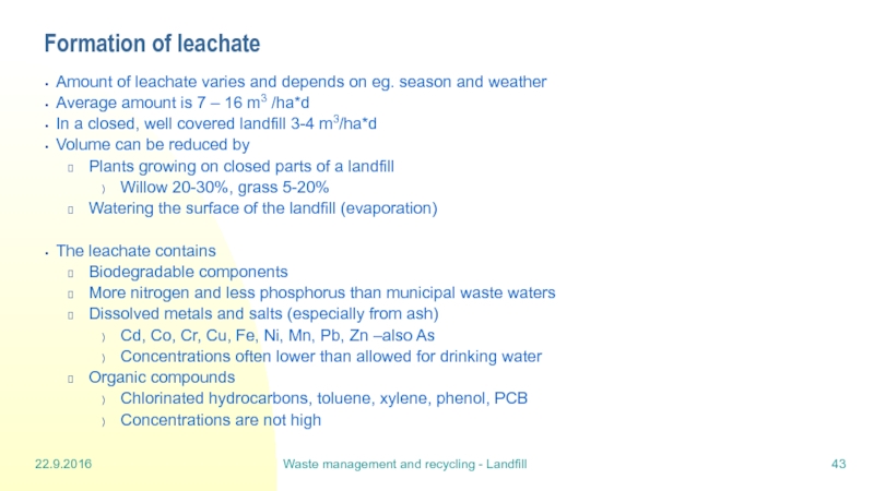
Leachate
Quality of leachate depends on
the
Leachate can also be circulated
in the waste layers ? nutrients and
humidity to the microbes
Слайд 4522.9.2016
Waste management and recycling - Landfill
Construction of a landfill before filling
The landfill has to be specially founded
Road construction
Land construction and quarrying
Re-inforcement of the bottom soil
Waterproofing the bottom and walls
the landfill is segregated from the bottom soil with
chemically and physically durable liner
prevents the ground water pollution
Collection system for leachate and surface water
no water runs off uncontrolled
Gas collection system
no gaseous emissions should be released
Buildings (office, storage, reception..)
Слайд 4622.9.2016
Waste management and recycling - Landfill
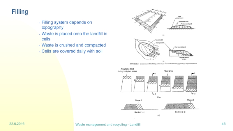
Filling
Filling system depends on topography
Waste is
Waste is crushed and compacted
Cells are covered daily with soil
Слайд 4722.9.2016
Waste management and recycling - Landfill
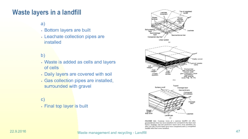
Waste layers in a landfill
a)
Bottom layers
Leachate collection pipes are installed
b)
Waste is added as cells and layers of cells
Daily layers are covered with soil
Gas collection pipes are installed, surrounded with gravel
c)
Final top layer is built
Слайд 4822.9.2016
Waste management and recycling - Landfill
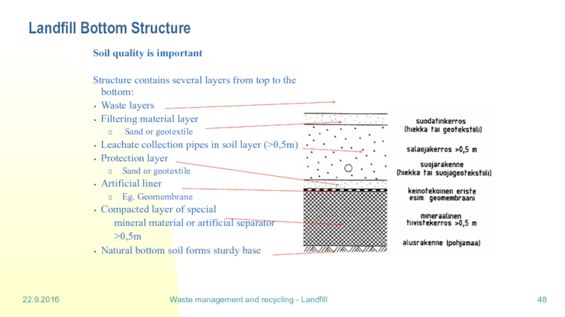
Landfill Bottom Structure
Soil quality is important
Structure contains several layers from top to the bottom:
Waste layers
Filtering material layer
Sand or geotextile
Leachate collection pipes in soil layer (>0,5m)
Protection layer
Sand or geotextile
Artificial liner
Eg. Geomembrane
Compacted layer of special
mineral material or artificial separator
>0,5m
Natural bottom soil forms sturdy base
Слайд 4922.9.2016
Waste management and recycling - Landfill
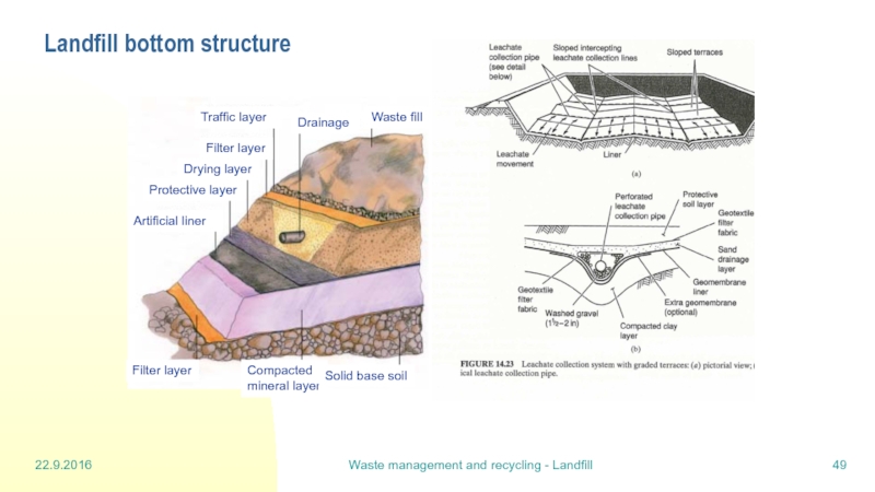
Landfill bottom structure
Waste fill
Drainage
Traffic layer
Filter layer
Drying
Protective layer
Artificial liner
Filter layer
Compacted
mineral layer
Solid base soil
Слайд 5022.9.2016
Waste management and recycling - Landfill
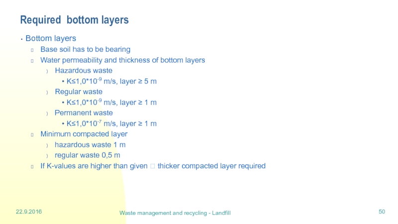
Required bottom layers
Bottom layers
Base soil has
Water permeability and thickness of bottom layers
Hazardous waste
K≤1,0*10-9 m/s, layer ≥ 5 m
Regular waste
K≤1,0*10-9 m/s, layer ≥ 1 m
Permanent waste
K≤1,0*10-7 m/s, layer ≥ 1 m
Minimum compacted layer
hazardous waste 1 m
regular waste 0,5 m
If K-values are higher than given ? thicker compacted layer required
Слайд 5122.9.2016
Waste management and recycling - Landfill
An example of bottom liners and
Слайд 5329.9.2016
Waste management and recycling - Composting
Definitions
Composting = aerobic biological decomposition
Composting is a natural process that can be enhanced with technical methods
Composting can reduce
The amount of waste in landfills
The nutrient and CH4 emissions from landfills
Composting can produce
Organic part of soil for land applications
Heat and gaseous products (mainly CO2)
Composting is operated
Municipally
In a household or housing company
Слайд 5429.9.2016
Waste management and recycling - Composting
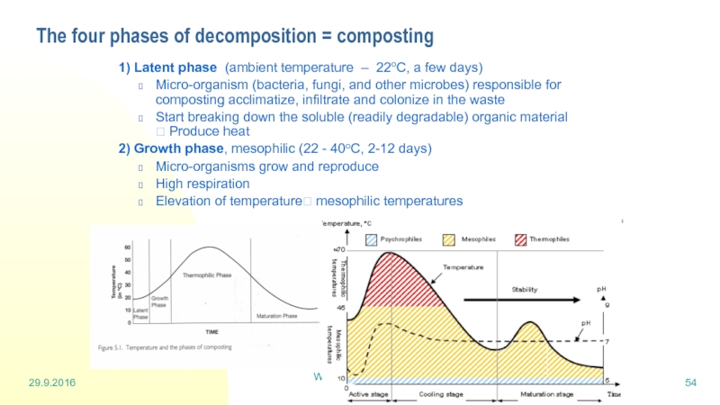
The four phases of decomposition
1) Latent phase (ambient temperature – 22oC, a few days)
Micro-organism (bacteria, fungi, and other microbes) responsible for composting acclimatize, infiltrate and colonize in the waste
Start breaking down the soluble (readily degradable) organic material ? Produce heat
2) Growth phase, mesophilic (22 - 40oC, 2-12 days)
Micro-organisms grow and reproduce
High respiration
Elevation of temperature? mesophilic temperatures
Слайд 5529.9.2016
Waste management and recycling - Composting
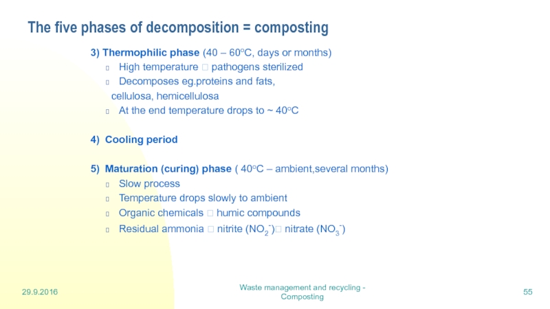
The five phases of decomposition
3) Thermophilic phase (40 – 60oC, days or months)
High temperature ? pathogens sterilized
Decomposes eg.proteins and fats,
cellulosa, hemicellulosa
At the end temperature drops to ~ 40oC
4) Cooling period
5) Maturation (curing) phase ( 40oC – ambient,several months)
Slow process
Temperature drops slowly to ambient
Organic chemicals ? humic compounds
Residual ammonia ? nitrite (NO2-)? nitrate (NO3-)
Слайд 5629.9.2016
Waste management and recycling - Composting
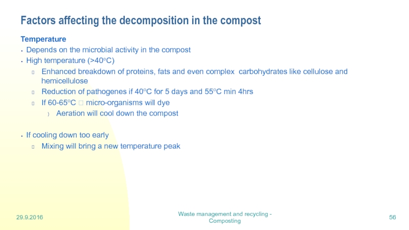
Factors affecting the decomposition in
Temperature
Depends on the microbial activity in the compost
High temperature (>40oC)
Enhanced breakdown of proteins, fats and even complex carbohydrates like cellulose and hemicellulose
Reduction of pathogenes if 40oC for 5 days and 55oC min 4hrs
If 60-65oC ? micro-organisms will dye
Aeration will cool down the compost
If cooling down too early
Mixing will bring a new temperature peak
Слайд 5729.9.2016
Waste management and recycling - Composting
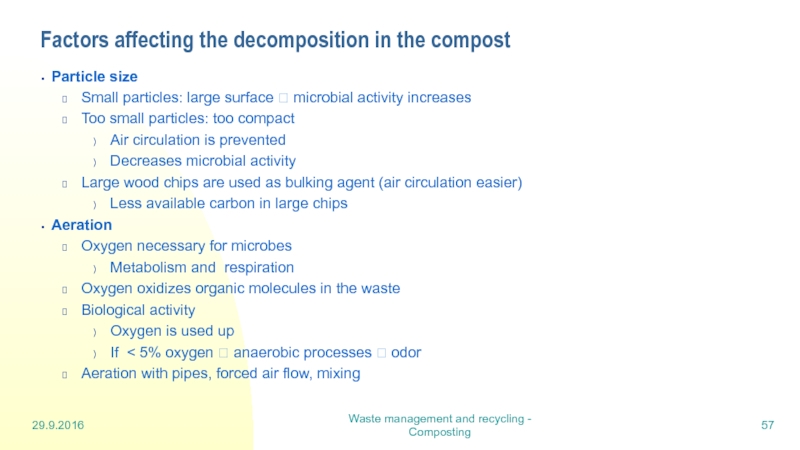
Factors affecting the decomposition in
Particle size
Small particles: large surface ? microbial activity increases
Too small particles: too compact
Air circulation is prevented
Decreases microbial activity
Large wood chips are used as bulking agent (air circulation easier)
Less available carbon in large chips
Aeration
Oxygen necessary for microbes
Metabolism and respiration
Oxygen oxidizes organic molecules in the waste
Biological activity
Oxygen is used up
If < 5% oxygen ? anaerobic processes ? odor
Aeration with pipes, forced air flow, mixing
Слайд 5829.9.2016
Waste management and recycling - Composting
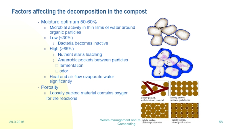
Factors affecting the decomposition in
Moisture optimum 50-60%
Microbial activity in thin films of water around organic particles
Low (<30%)
Bacteria becomes inactive
High (>65%)
Nutrient starts leaching
Anaerobic pockets between particles
? fermentation
? odor
Heat and air flow evaporate water significantly
Porosity
Loosely packed material contains oxygen
for the reactions
Слайд 5929.9.2016
Waste management and recycling - Composting
Factors affecting the decomposition in
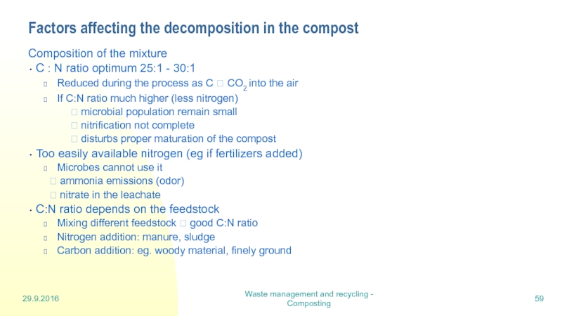
Composition of the mixture
C : N ratio optimum 25:1 - 30:1
Reduced during the process as C ? CO2 into the air
If C:N ratio much higher (less nitrogen)
? microbial population remain small
? nitrification not complete
? disturbs proper maturation of the compost
Too easily available nitrogen (eg if fertilizers added)
Microbes cannot use it
? ammonia emissions (odor)
? nitrate in the leachate
C:N ratio depends on the feedstock
Mixing different feedstock ? good C:N ratio
Nitrogen addition: manure, sludge
Carbon addition: eg. woody material, finely ground
Слайд 6029.9.2016
Waste management and recycling - Composting
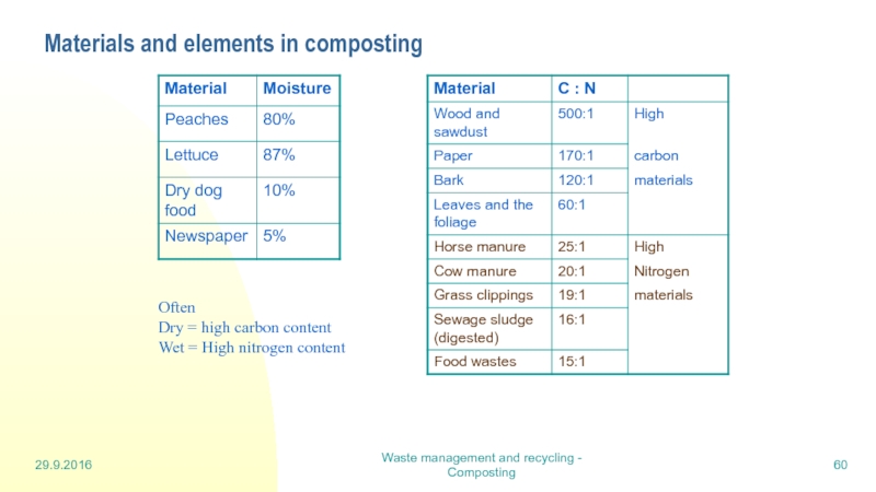
Materials and elements in composting
Often
Dry = high carbon content
Wet = High nitrogen content
Слайд 6129.9.2016
Waste management and recycling - Composting
Factors affecting the decomposition in
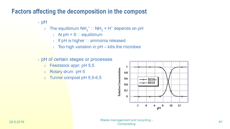
pH
The equilibrium NH4+ ? NH3 + H+ depends on pH
At pH = 9 ? equilibrium
If pH is higher ? ammonia released
Too high variation in pH – kills the microbes
pH of certain stages or processes
Feedstock appr. pH 5,5
Rotary drum pH 5
Tunnel compost pH 5,5-6,5
Слайд 6229.9.2016
Waste management and recycling - Composting
Factors affecting the decomposition in
Odors are caused if
Feedstock is stored anaerobically previous to the composting
In compost: low oxygen or anaerobic conditions cause odorouos compounds
Reduced sulfur compounds (eg. H2S)
Volatile fatty acids
Aromatic compounds and amines
High pH ? ammonia
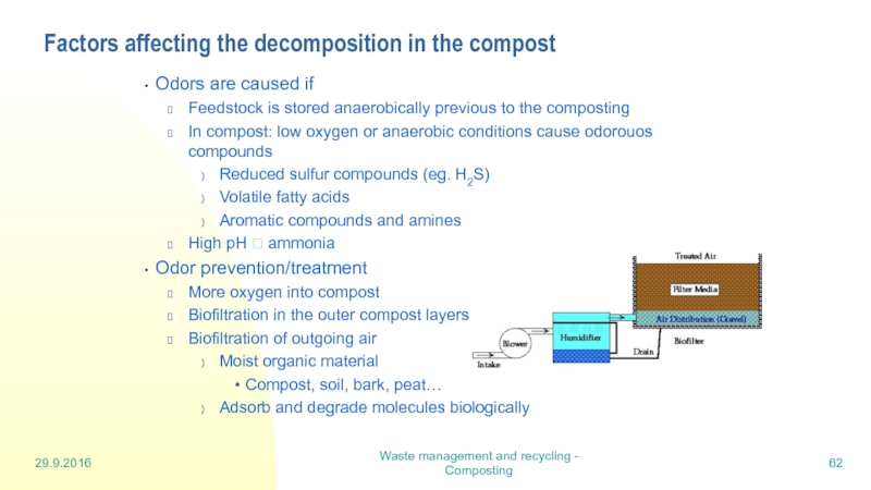
Odor prevention/treatment
More oxygen into compost
Biofiltration in the outer compost layers
Biofiltration of outgoing air
Moist organic material
Compost, soil, bark, peat…
Adsorb and degrade molecules biologically
Слайд 6329.9.2016
Waste management and recycling - Composting
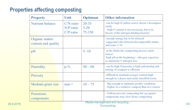
Properties affecting composting
Taulukko 3.1 Jätteen
Слайд 656.10.2016
Waste management and recycling - Digestion
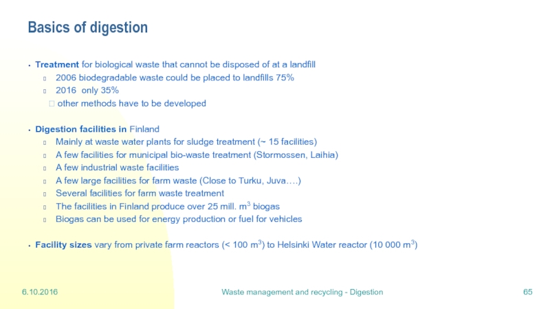
Basics of digestion
Treatment for biological waste
2006 biodegradable waste could be placed to landfills 75%
2016 only 35%
? other methods have to be developed
Digestion facilities in Finland
Mainly at waste water plants for sludge treatment (~ 15 facilities)
A few facilities for municipal bio-waste treatment (Stormossen, Laihia)
A few industrial waste facilities
A few large facilities for farm waste (Close to Turku, Juva….)
Several facilities for farm waste treatment
The facilities in Finland produce over 25 mill. m3 biogas
Biogas can be used for energy production or fuel for vehicles
Facility sizes vary from private farm reactors (< 100 m3) to Helsinki Water reactor (10 000 m3)
Слайд 666.10.2016
Waste management and recycling - Digestion
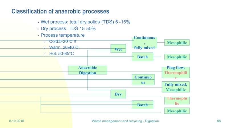
Classification of anaerobic processes
Wet process: total
Dry process: TDS 15-50%
Process temperature
Cold:5-20oC !!
Warm: 20-40oC
Hot: 50-65oC
Слайд 676.10.2016
Waste management and recycling - Digestion
Digestion process
Biological reactions in the
Hydrolysis: fermentative bacteria hydrolyze complicated organic compounds into soluble organics more available for the next stage
Enzymes produced by hydrolytic bacteria decompose and liquefy carbohydrates, cellulose, proteins and fats
Rate limited: decomposing the complex compounds like cellulose
Rate governed by
Substrate availability
Bacterial population density
Temperature and pH
Acidogenesis (acidogenesis and acetogenesis): products of the
hydrolysis are further processed by bacteria
Main products: acetic, lactic and propionic acids
Acetic acid is produced from monomers
Volatile fatty acids (VFA) are produced from protein, fat and carbohydrate components
Some gases (CO2, H2) and methanol are produced
pH falls
Products depend on feedstock, bacteria species and environmental conditions
Слайд 686.10.2016
Waste management and recycling - Digestion
Digestion process
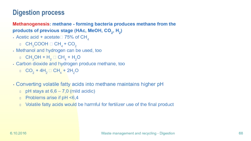
Methanogenesis: methane - forming bacteria
products of previous stage (HAc, MeOH, CO2, H2)
Acetic acid + acetate? 75% of CH4
CH3COOH ? CH4 + CO2
Methanol and hydrogen can be used, too
CH3OH + H2 ? CH4 + H2O
Carbon dioxide and hydrogen produce methane, too
CO2 + 4H2 ? CH4 + 2H2O
Converting volatile fatty acids into methane maintains higher pH
pH stays at 6,6 – 7,0 (mild acidic)
Problems arise if pH <6,4
Volatile fatty acids would be harmful for fertilizer use of the final product
Слайд 696.10.2016
Waste management and recycling - Digestion
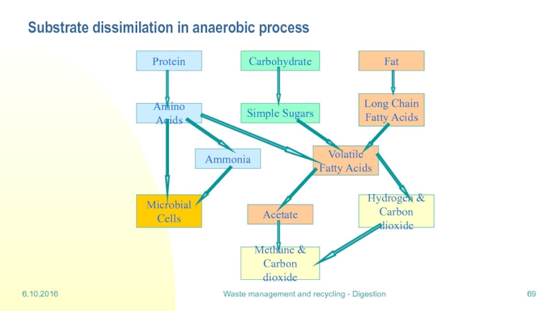
Substrate dissimilation in anaerobic process
Protein
Carbohydrate
Fat
Long
Fatty Acids
Simple Sugars
Amino Acids
Volatile
Fatty Acids
Ammonia
Hydrogen &
Carbon dioxide
Acetate
Microbial
Cells
Methane &
Carbon dioxide
Слайд 706.10.2016
Waste management and recycling - Digestion
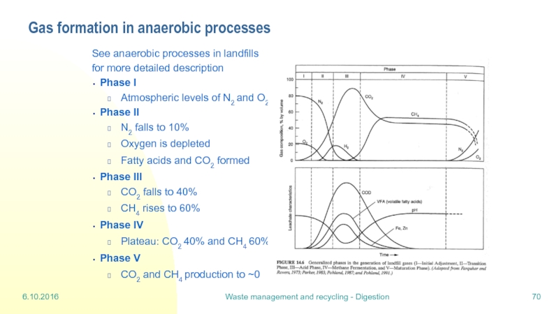
Gas formation in anaerobic processes
See anaerobic
for more detailed description
Phase I
Atmospheric levels of N2 and O2
Phase II
N2 falls to 10%
Oxygen is depleted
Fatty acids and CO2 formed
Phase III
CO2 falls to 40%
CH4 rises to 60%
Phase IV
Plateau: CO2 40% and CH4 60%
Phase V
CO2 and CH4 production to ~0
Слайд 7213.10.2016
Waste management and recycling - incineration 2
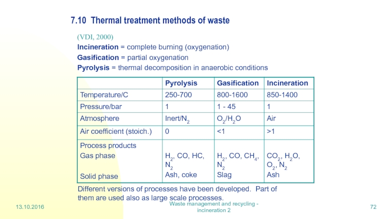
7.10 Thermal treatment methods of
(VDI, 2000)
Incineration = complete burning (oxygenation)
Gasification = partial oxygenation
Pyrolysis = thermal decomposition in anaerobic conditions
Different versions of processes have been developed. Part of them are used also as large scale processes.
Слайд 7313.10.2016
Waste management and recycling - incineration 2
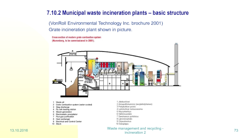
7.10.2 Municipal waste incineration plants
(VonRoll Environmental Technology Inc. brochure 2001)
Grate incineration plant shown in picture.
Слайд 7413.10.2016
Waste management and recycling - incineration 2
Grate firing
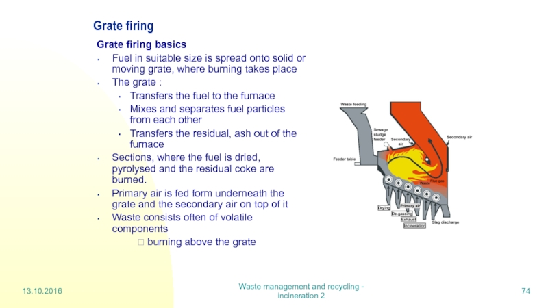
Grate firing basics
Fuel
The grate :
Transfers the fuel to the furnace
Mixes and separates fuel particles from each other
Transfers the residual, ash out of the furnace
Sections, where the fuel is dried, pyrolysed and the residual coke are burned.
Primary air is fed form underneath the grate and the secondary air on top of it
Waste consists often of volatile components
? burning above the grate
Слайд 7513.10.2016
Waste management and recycling - incineration 2
Grate firing (cont)
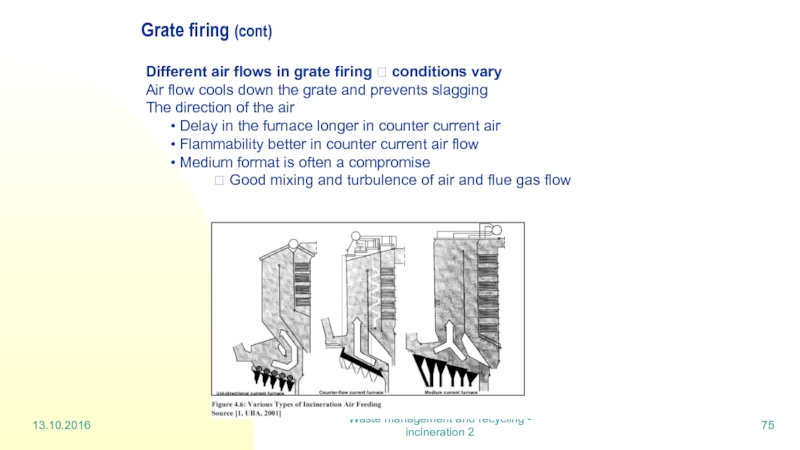
Different air flows
Air flow cools down the grate and prevents slagging
The direction of the air
Delay in the furnace longer in counter current air
Flammability better in counter current air flow
Medium format is often a compromise
? Good mixing and turbulence of air and flue gas flow
Слайд 7613.10.2016
Waste management and recycling - incineration 2
Grate firing (cont)
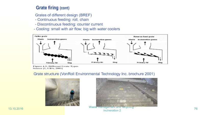
Grate structure (VonRoll
Grates of different design (BREF)
- Continuous feeding: roll, chain
- Discontinuous feeding: counter current
Cooling: small with air flow; big with water coolers
Слайд 7713.10.2016
Waste management and recycling - incineration 2
Grate firing (cont)
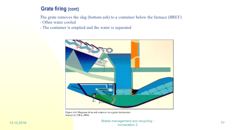
The grate removes
- Often water cooled
- The container is emptied and the water is separated
Слайд 7813.10.2016
Waste management and recycling - incineration 2
Fluidised bed incineration
Fluidised bed
coal (dust), sludge, biomass (wood)
sorted waste is required for waste incineration
? homogeneous recycled fuel
well managed and reliable incineration method
flue gas cleaning is cheaper
Principle of fluidised bed incineration
inert bed material (sand, ash) floats in the reactor
air is fed from beneath ? floats the mass
bed material has to be heated before feeding the waste
(oil or gas burners are used)
waste has to be finely structured, max. 50 mm
feeding among or above the fluidised bed material,
turbulence is important ? mixes the fuel, bed material and air
Слайд 7913.10.2016
Waste management and recycling - incineration 2
Fluidised bed incineration (cont)
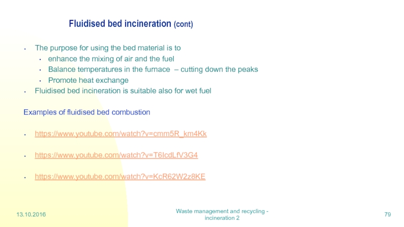
The purpose
enhance the mixing of air and the fuel
Balance temperatures in the furnace – cutting down the peaks
Promote heat exchange
Fluidised bed incineration is suitable also for wet fuel
Examples of fluidised bed combustion
https://www.youtube.com/watch?v=cmm5R_km4Kk
https://www.youtube.com/watch?v=T6IcdLfV3G4
https://www.youtube.com/watch?v=KcR62W2z8KE
Слайд 8013.10.2016
Waste management and recycling - incineration 2
Fluidised bed incineration (cont)
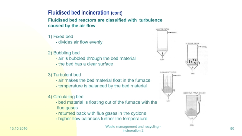
Fluidised
1) Fixed bed
divides air flow evenly
2) Bubbling bed
air is bubbled through the bed material
the bed has a clear surface
3) Turbulent bed
air makes the bed material float in the furnace
temperature is balanced by the bed material
4) Circulating bed
bed material is floating out of the furnace with the flue gases
returned back with flue gases in the cyclone
higher flow balances further the temperature
Слайд 8113.10.2016
Waste management and recycling - incineration 2
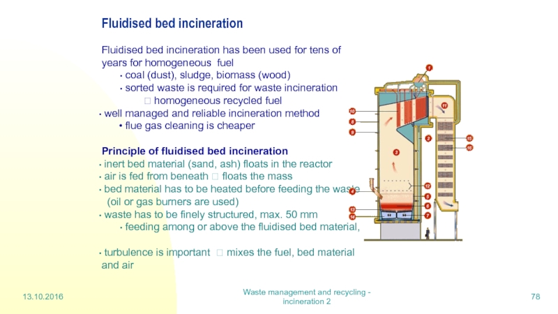
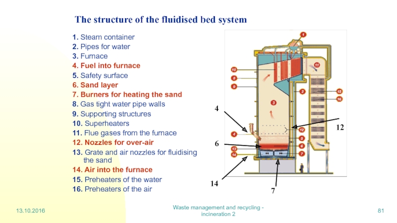
The structure of the fluidised
1. Steam container
2. Pipes for water
3. Furnace
4. Fuel into furnace
5. Safety surface
6. Sand layer
7. Burners for heating the sand
8. Gas tight water pipe walls
9. Supporting structures
10. Superheaters
11. Flue gases from the furnace
12. Nozzles for over-air
13. Grate and air nozzles for fluidising the sand
14. Air into the furnace
15. Preheaters of the water
16. Preheaters of the air
4
14
7
12
6
Слайд 8213.10.2016
Waste management and recycling - incineration 2
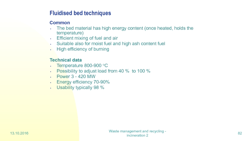
Fluidised bed techniques
Common
The bed
Efficient mixing of fuel and air
Suitable also for moist fuel and high ash content fuel
High efficiency of burning
Technical data
Temperature 800-900 oC
Possibility to adjust load from 40 % to 100 %
Power 3 - 420 MW
Energy efficiency 70-90%
Usability typically 98 %
Слайд 8313.10.2016
Waste management and recycling - incineration 2
Fluidised bed techniques (cont)
Small emissions
Moderate temperature:
Thermal formation of NO reduced
Fuel –NO still formed
alkaline bed material can be used to bind sulfur emissions in the furnace
Less oxygen (flue gas circulation)
N2O-emissions higher
Solid wastes (differences partly dependable on fuel quality)
Less bottom ash 10%
Fly ash 90%
Bottom ash contains more volatile metals than in grate firing
? less metals in flue gases
The ash quality more homogeneous
Less sintering of ash
Minor need for repair
Minor fouling if not much Cl, K, Na, Al in the waste
Слайд 8413.10.2016
Waste management and recycling - incineration 2
7.10.3 Pyrolysis and gasification
Optional
Commercial systems exists, but different methods in industrial scale are at different stages of development.
The target is
to add inorganic waste collection
change the waste into process gas
minimize the cleaning costs of the flue gas by reducing their volume
The methods decompose
the components of the waste ? chemical raw materials
different stages in burning processes ? different fuels
The methods used are
Temperature and pressure control
Special reactors
Often combined with incineration
Слайд 8513.10.2016
Waste management and recycling - incineration 2
Pyrolysis and gasification (cont)
Smouldering
Gas formation
400-600 oC
Pyrolysis
Decomposition of waste by heat produces gas
Energy content of gas 5 – 15 MJ/m3
600-800 oC (also given 400-700 oC)
Gasification
Gasification of coal to coke
Volatile compounds separated from the solid waste
Additional components: oxygen or water vapour
Gas= process gas (CO + H2)
800-1000 oC
Combined technology: burning included
In combined technology the coke from pyrolysis and the gas are burned
In Europe
Combustible non sorted municipal waste (RDF): a few pyrolysis sites in Germany for MSW treatment (2003)
Others for treatment of recycled fuel separated at source (REF)
Слайд 8613.10.2016
Waste management and recycling - incineration 2
Gasification
Several processes suitable for municipal
Gasification often combined to pyrolysis
gases are burned at a power plant
Fuel feeding (waste)
content and particle size limited
fine particles expected ? requires often pretreatment
hazardous waste (liquids, paste, fine grade) directly fed to the gasifier
Various processes
concurrent gasifier
cyclone gasifier
fluid bed gasifier
packed bed gasifier
Pressurised and atmospheric gasification plants exist.
Слайд 8713.10.2016
Waste management and recycling - incineration 2
Gasification (cont)
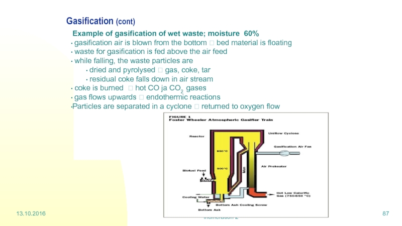
Example of gasification of
gasification air is blown from the bottom ? bed material is floating
waste for gasification is fed above the air feed
while falling, the waste particles are
dried and pyrolysed ? gas, coke, tar
residual coke falls down in air stream
coke is burned ? hot CO ja CO2 gases
gas flows upwards ? endothermic reactions
Particles are separated in a cyclone ? returned to oxygen flow
Слайд 8813.10.2016
Waste management and recycling - incineration 2
Gasification (cont
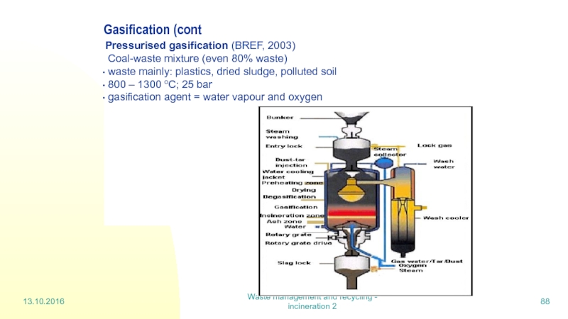
Pressurised gasification (BREF, 2003)
Coal-waste mixture (even 80% waste)
waste mainly: plastics, dried sludge, polluted soil
800 – 1300 oC; 25 bar
gasification agent = water vapour and oxygen
Слайд 8913.10.2016
Waste management and recycling - incineration 2
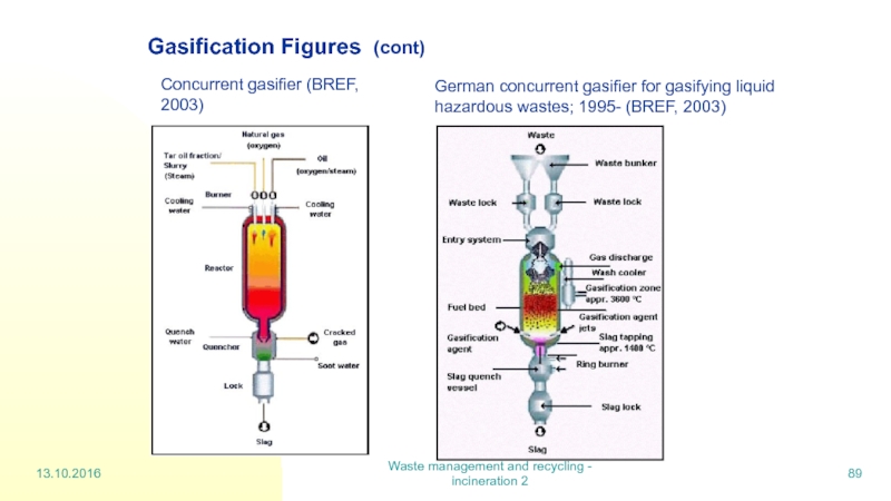
Gasification Figures (cont)
Concurrent gasifier (BREF,
German concurrent gasifier for gasifying liquid
hazardous wastes; 1995- (BREF, 2003)
Слайд 9013.10.2016
Waste management and recycling - incineration 2
Gasification (cont)
Benefits
gasification enables also
synthesis gas recovery as material and energy
less waste water from flue gas cleaning
less waste than in incineration
solid wastes ? slag
higher recovery rate of materials
can be combined with more efficient energy recovery methods (gas turbines, IGCC, fuel cells…)
smaller volumes of gas and equipment ( pressurised gasification)
incineration plant can be small
smaller flue gas ducts (chimneys)
image: ”green”, clean energy
for part of plants: cheaper electricity and heat
”green tariff” due to Kioto and emission trade
TABLE 1. Advantages of the new processes1
Слайд 9113.10.2016
Waste management and recycling - incineration 2
Gasification (cont)
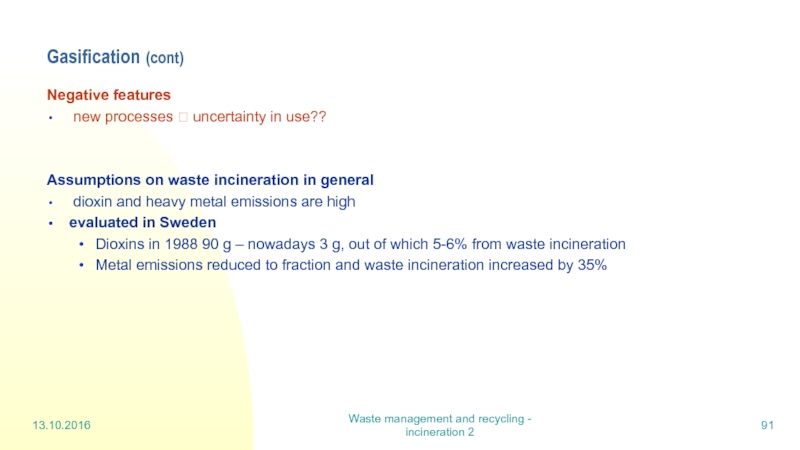
Negative features
new
Assumptions on waste incineration in general
dioxin and heavy metal emissions are high
evaluated in Sweden
Dioxins in 1988 90 g – nowadays 3 g, out of which 5-6% from waste incineration
Metal emissions reduced to fraction and waste incineration increased by 35%
Слайд 9320.10.2016
Waste management and recycling - Hazardous waste
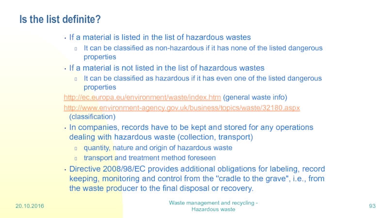
Is the list definite?
If a
It can be classified as non-hazardous if it has none of the listed dangerous properties
If a material is not listed in the list of hazardous wastes
It can be classified as hazardous if it has even one of the listed dangerous properties
http://ec.europa.eu/environment/waste/index.htm (general waste info)
http://www.environment-agency.gov.uk/business/topics/waste/32180.aspx (classification)
In companies, records have to be kept and stored for any operations dealing with hazardous waste (collection, transport)
quantity, nature and origin of hazardous waste
transport and treatment method foreseen
Directive 2008/98/EC provides additional obligations for labeling, record keeping, monitoring and control from the "cradle to the grave", i.e., from the waste producer to the final disposal or recovery.
Слайд 94Types of hazardous waste
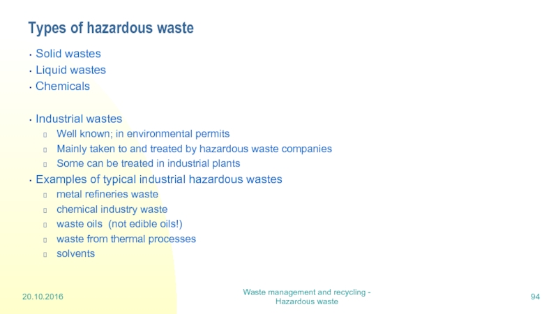
Solid wastes
Liquid wastes
Chemicals
Industrial wastes
Well known; in environmental permits
Mainly
Some can be treated in industrial plants
Examples of typical industrial hazardous wastes
metal refineries waste
chemical industry waste
waste oils (not edible oils!)
waste from thermal processes
solvents
20.10.2016
Waste management and recycling - Hazardous waste
Слайд 95Treatment, main aspects
Sorted and labelled waste
Waste to energy
Thermal treatment
Physico-chemical treatment
Biological
Material recovery
Special treatments
Final disposal
20.10.2016
Waste management and recycling - Hazardous waste
Слайд 961 High temperature incineration
Process units at Ekokem
The core unit is a
1 300oC (Directive 2000/76/EU For Hazardous waste >1100 oC for 2 s )
Long delay time in kiln and after-burn ? complete decomposition and burning
Energy is recovered ? electricity and district heat
The slag can be used e.g. in soil construction
Flue gases are cleaned
Cooling
Acid gases washing by lime
Particle removal by electrostatic precipitator
Gaseous emissions: further scrubbing
Dioxine and mercury removal by activated charcoal
At Riihimäki, the energy produced comparable to 43 milj. m3 natural gas.
20.10.2016
Waste management and recycling - Hazardous waste
Слайд 97
High temperature incineration of hazardous waste
20.10.2016
Waste management and recycling - Hazardous
Water
treatment
Steam production
Feeding
solid waste
Rotary kiln 1200-1350oC
Feeding packed waste
Ash silo
Activated
carbon
Fiber filter
Electrical
Precipitatori
Evaporation tower
Flue gas
analysis
HCL scrubber
SO2
scrubber
Lime production
Heat exchanger
After burner 900-1100oC
Ash
c
Feeding
Liquid waste
Flue gas fan
Filter press.
Solids to landfill
Slag
Слайд 984 Physico- chemical processes
Inorganic wastes, such as acids, bases and heavy
Main methods
Neutralization of acid and bases
Precipitation of heavy metals
The remaining water is purified for use in processes
Oxidation and reduction reactions
Notice: one type of waste can be used for processing another type of waste
Acid + base
Precipitating media
20.10.2016
Waste management and recycling - Hazardous waste
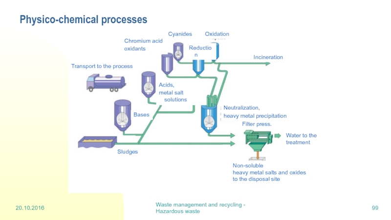
Слайд 99Physico-chemical processes
20.10.2016
Waste management and recycling - Hazardous waste
Non-soluble
heavy metal salts
to the disposal site
Water to the treatment
Filter press.
Reduction
Cyanides
Bases
Chromium acid
oxidants
Acids,
metal salt solutions
Neutralization,
heavy metal precipitation
Oxidation
Sludges
Incineration
Transport to the process
Слайд 101Waste management and recycling - LCA
10 Life Cycle Assessment = LCA
Various
Life cycle analysis, LCA
Life cycle inventory, LCI
Also: material flow analysis, eco-balancing, cradle to grave analysis, LCIA: life cycle impact assessment (ecological dimensions), SLCC: Social life cycle costs….
A study of a product’s, service’s or particular action’s environmental effects deriving from the whole life cycle of the product
Includes
the indirect effects and emissions, for e.g. a car
manufacturing process of a car, extraction of raw materials, final disposal
operational stage (which would in a car’s case include fuel consumption, tyres, lubrication, repair parts etc.)
LCA does not take economical or social aspects into consideration??
The economists use similar LCC (life cycle costs); SLCC
3.11.2016
Слайд 102Waste management and recycling - LCA
Life Cycle Assessment = LCA
Main idea
Materials needed to produce the product
Energy needed to produce the product
Transportation to end users
Use of the product
Need of energy during the use
Need of maintenance (e.g. paint)
Discarding the product
Calculate for all stages above
all materials, energy and emissions
environmental impacts (global warming, air pollution, water pollution, environmental health consequences…)
Have this all in numbers to be able to compare two products
3.11.2016
Слайд 103Waste management and recycling - LCA
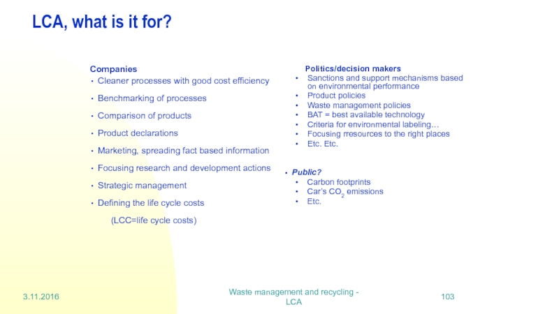
LCA, what is it for?
Companies
Cleaner processes
Benchmarking of processes
Comparison of products
Product declarations
Marketing, spreading fact based information
Focusing research and development actions
Strategic management
Defining the life cycle costs
(LCC=life cycle costs)
Politics/decision makers
Sanctions and support mechanisms based on environmental performance
Product policies
Waste management policies
BAT = best available technology
Criteria for environmental labeling…
Focusing rresources to the right places
Etc. Etc.
Public?
Carbon footprints
Car’s CO2 emissions
Etc.
3.11.2016
Слайд 104Waste management and recycling - LCA
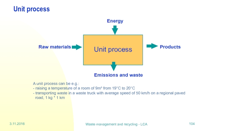
Unit process
A unit process can be
road, 1 kg * 1 km
3.11.2016
Слайд 105Waste management and recycling - LCA
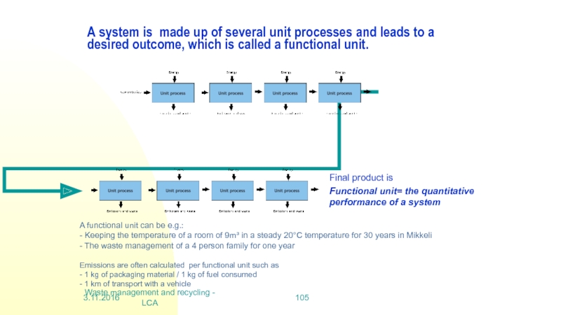
A system is made up of
Final product is
Functional unit= the quantitative performance of a system
A functional unit can be e.g.:
- Keeping the temperature of a room of 9m³ in a steady 20°C temperature for 30 years in Mikkeli
- The waste management of a 4 person family for one year
Emissions are often calculated per functional unit such as
- 1 kg of packaging material / 1 kg of fuel consumed
- 1 km of transport with a vehicle
3.11.2016
Слайд 106Waste management and recycling - LCA
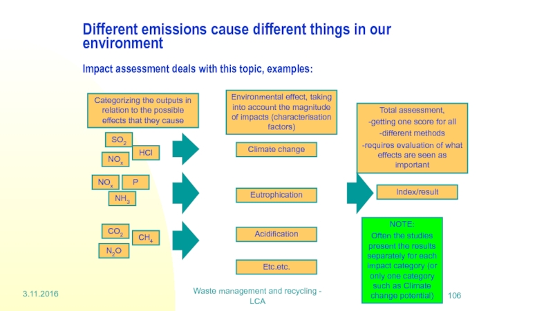
Different emissions cause different things in
Index/result
Climate change
Eutrophication
Acidification
Etc.etc.
SO2
NOx
HCl
NH3
P
NOx
CO2
CH4
N2O
Categorizing the outputs in relation to the possible effects that they cause
Environmental effect, taking into account the magnitude of impacts (characterisation factors)
Total assessment,
-getting one score for all
-different methods
-requires evaluation of what effects are seen as important
NOTE:
Often the studies present the results separately for each impact category (or only one category such as Climate change potential)
3.11.2016
Слайд 107Waste management and recycling - LCA
Impact assessment methods - Midpoint
Methods are
Midpoint is the preferred way according to ISO standard
Midpoint methods include:
Resource use (raw materials, land, energy)
Health effects
Ecological effects
The environmental effect indicators should present the results with
only a reasonable amount of uncertainty
in a form that is usable for the interest groups
Middlepoint methods leads to the fact that the results may be given in many different units
This can make it difficult to analyse which effect is the most important in the total system.
3.11.2016
Слайд 108Waste management and recycling - LCA
Impact assessment methods - Midpoint cont.
Midpoint-oriented
Example:
Global Warming Potential (GWP) is not expressed in temperature change in the atmosphere (this would be ”quite” difficult), but it is expressed in e.g. CO2-equivalents
Different emissions are valued to the same global warming potential scale with CO2 by characterisation factors (eg methane’s factor is 21 or 25 depending on the method)
Characterisation of emissions by their actual effects is difficult, especially for human health effects or ecotoxicity
http://www.waterfootprint.org/?page=files/home
3.11.2016
Слайд 109Waste management and recycling - LCA
Impact assessment methods –
Endpoint or
Endpoint or damage oriented methods take a step further than midpoint methods
Endpoint methods present results in the following categories:
Resource extraction
Human health
Ecosystem quality
Endpoint= the negative phenomena in the environment, human health or natural resources that can be linked to a ceartain emission that causes it
E.g. climate warming will cause problems for human health
?Human heath is the endpoint
? Emissions that cause the damage to human health are middlepoints.
In real world, the characterisation factors for certain emissions vary according to the surrounding environment. Global effects are however different: Climate change and ozone layer depletion are truly global problems, it does not matter where you produce the emissions
3.11.2016

