- Главная
- Разное
- Дизайн
- Бизнес и предпринимательство
- Аналитика
- Образование
- Развлечения
- Красота и здоровье
- Финансы
- Государство
- Путешествия
- Спорт
- Недвижимость
- Армия
- Графика
- Культурология
- Еда и кулинария
- Лингвистика
- Английский язык
- Астрономия
- Алгебра
- Биология
- География
- Детские презентации
- Информатика
- История
- Литература
- Маркетинг
- Математика
- Медицина
- Менеджмент
- Музыка
- МХК
- Немецкий язык
- ОБЖ
- Обществознание
- Окружающий мир
- Педагогика
- Русский язык
- Технология
- Физика
- Философия
- Химия
- Шаблоны, картинки для презентаций
- Экология
- Экономика
- Юриспруденция
Line differential protection 7SD52x / 7SD610. Siemens презентация
Содержание
- 1. Line differential protection 7SD52x / 7SD610. Siemens
- 2. Line differential relays 87L- SIPROTEC 4
- 3. Customer Benefits The protection adapts
- 4. Hardware options 7SD610
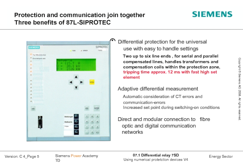
- 5. Protection and communication join together Three benefits of 87L-SIPROTEC
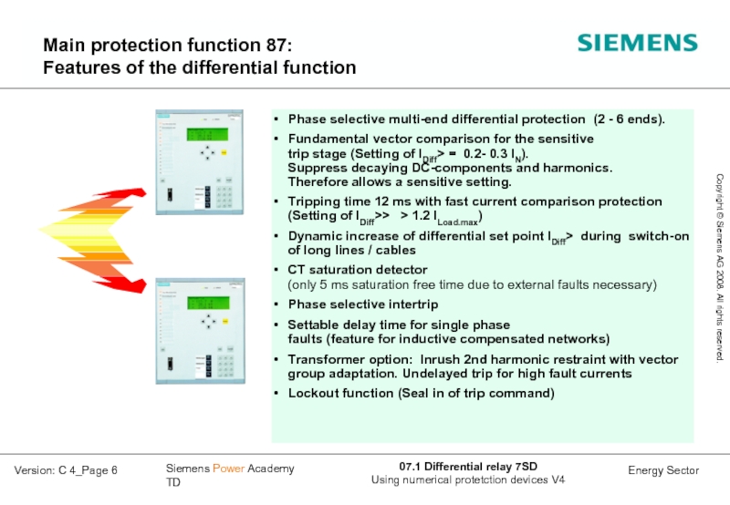
- 6. Main protection function 87: Features of the differential function
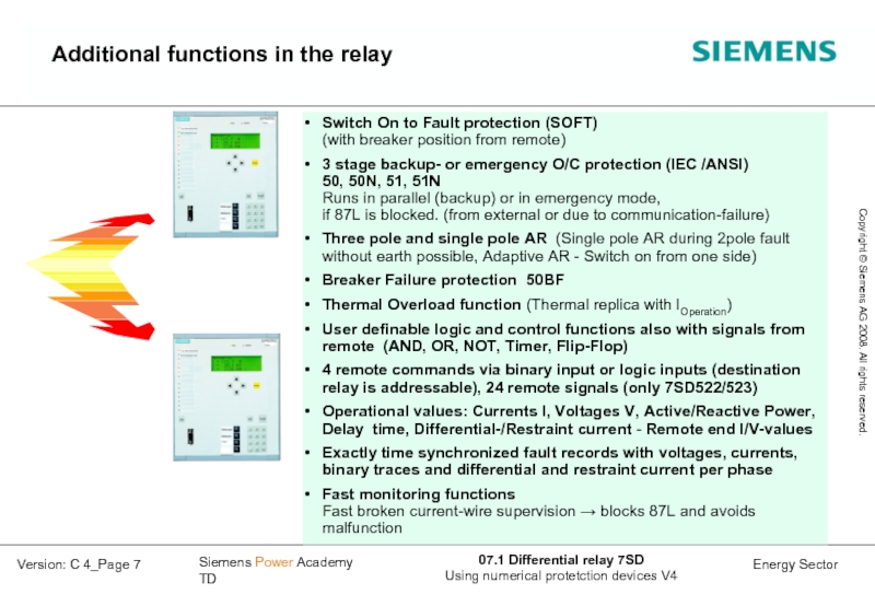
- 7. Additional functions in the relay
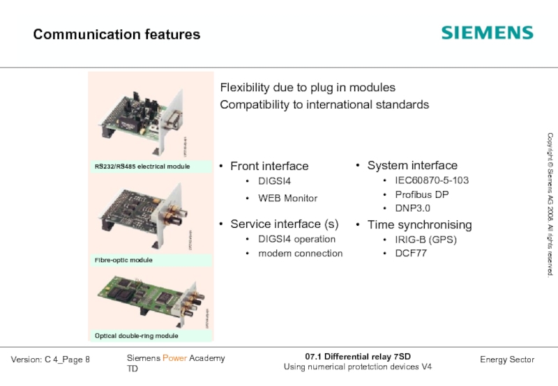
- 8. Communication features
- 9. IDiff>: Vector comparison
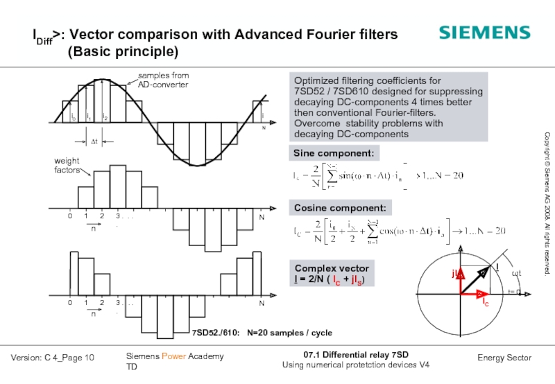
- 10. IDiff>: Vector comparison with Advanced Fourier filters
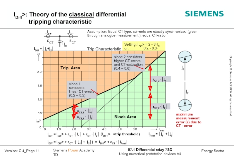
- 11. IDiff>: Theory of the classical differential tripping characteristic
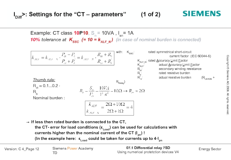
- 12. Example: CT class 10P10, Sn = 10VA
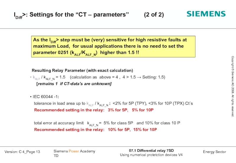
- 13. IDiff>: Settings for the “CT – parameters” (2 of 2)
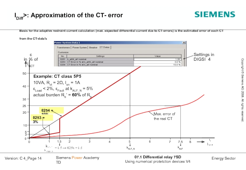
- 14. IDiff>: Approximation of the CT- error
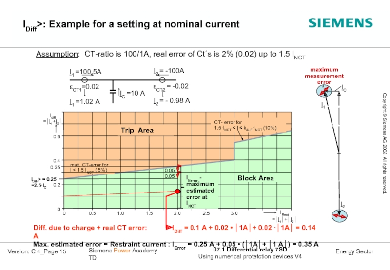
- 15. IDiff>: Example for a setting at nominal current
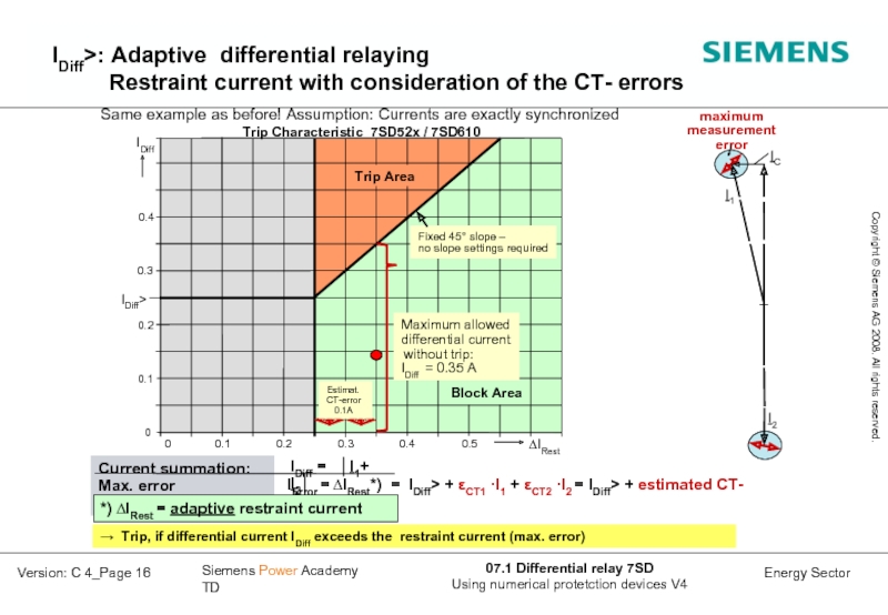
- 16. IDiff>: Adaptive differential relaying
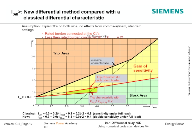
- 17. IDiff>: New differential method compared with a classical differential characteristic
- 18. 5P20, 20 VA 1600/1A kALF/ kALF_N
- 19. IDiff>: CT- saturation detector based on harmonic
- 20. Trip, if differential current exceeds the estimated
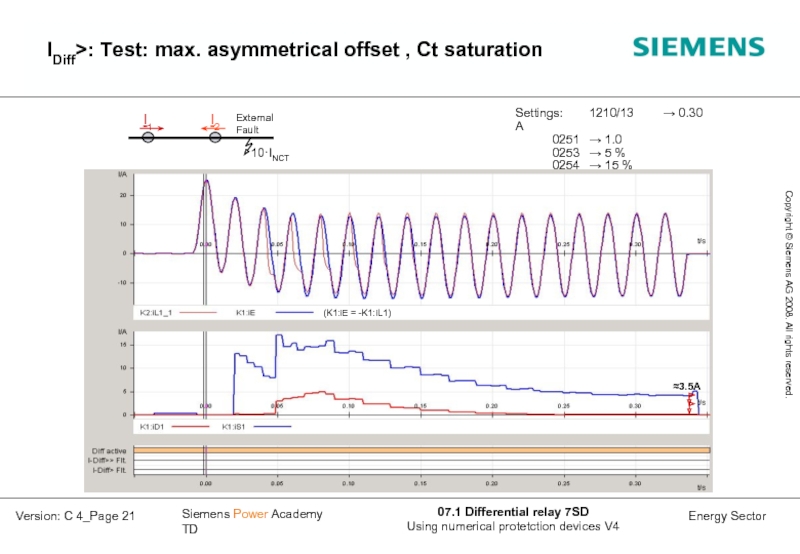
- 21. IDiff>: Test: max. asymmetrical offset , Ct saturation
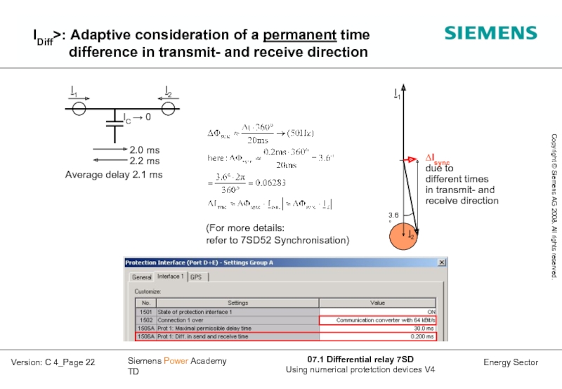
- 22. IDiff>: Adaptive consideration of a permanent time
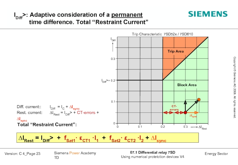
- 23. IDiff>: Adaptive consideration of a permanent
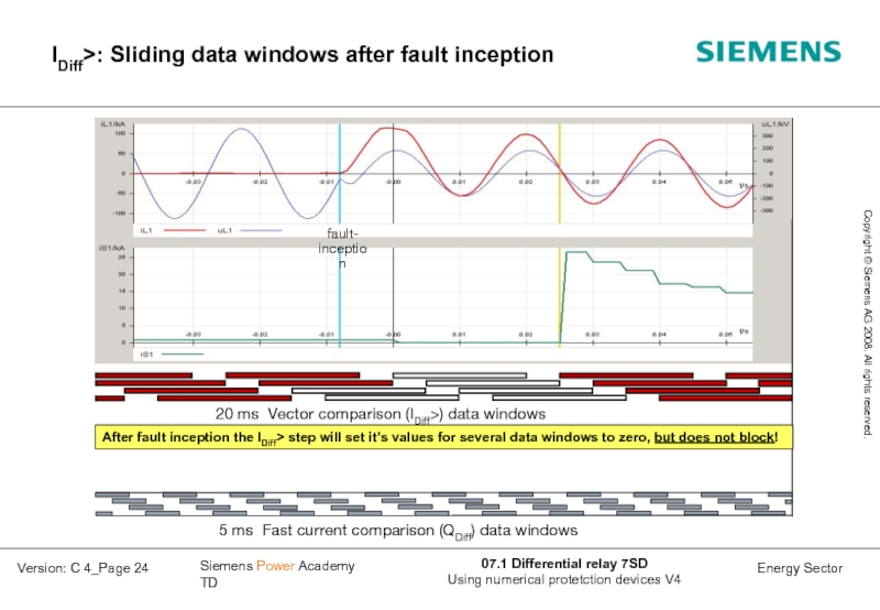
- 24. IDiff>: Sliding data windows after fault inception
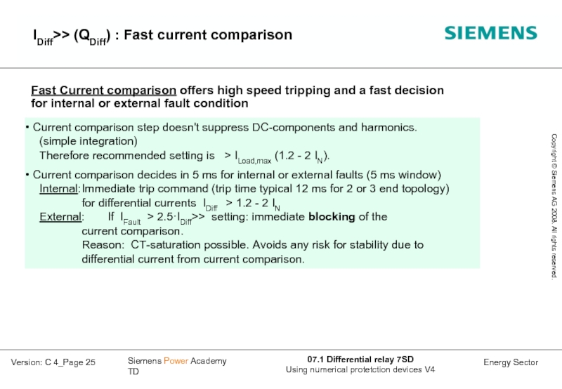
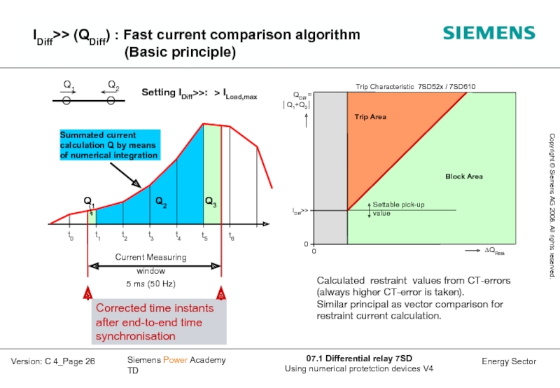
- 25. IDiff>> (QDiff) : Fast current comparison
- 26. IDiff>> (QDiff) : Fast current comparison algorithm
- 27. CT- requirements, mismatch of the primary CT currents
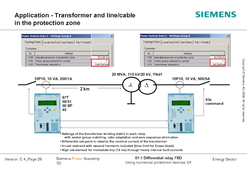
- 28. Application - Transformer and line/cable in
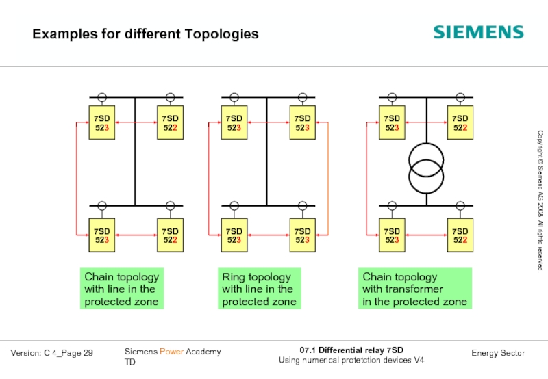
- 29. Examples for different Topologies
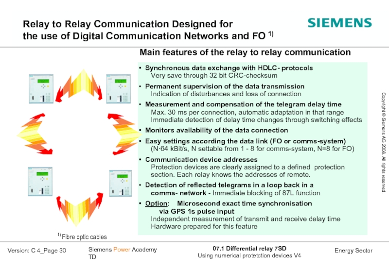
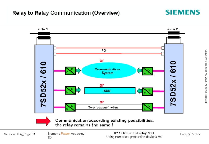
- 30. Relay to Relay Communication Designed for the
- 31. Relay to Relay Communication (Overview) side
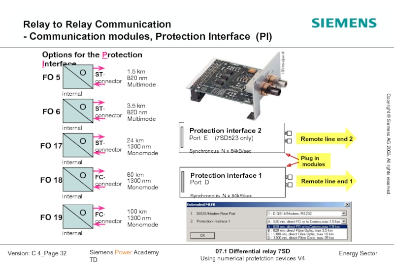
- 32. Relay to Relay Communication - Communication modules,
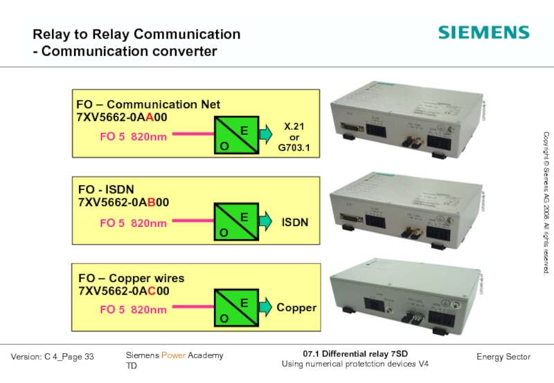
- 33. Relay to Relay Communication - Communication converter
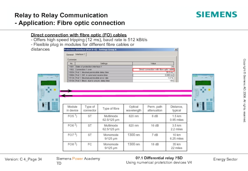
- 34. Relay to Relay Communication - Application:
- 35. Relay to Relay Communication - Application:
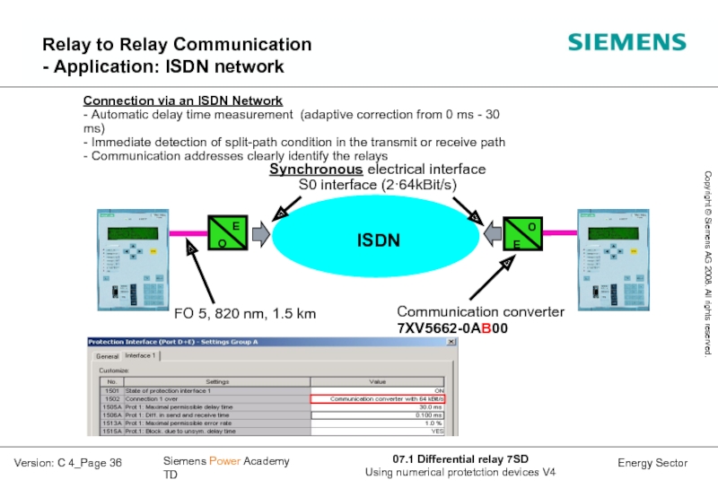
- 36. Relay to Relay Communication - Application: ISDN network
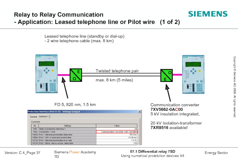
- 37. Relay to Relay Communication - Application:
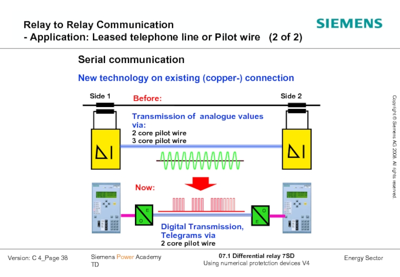
- 38. Relay to Relay Communication - Application:
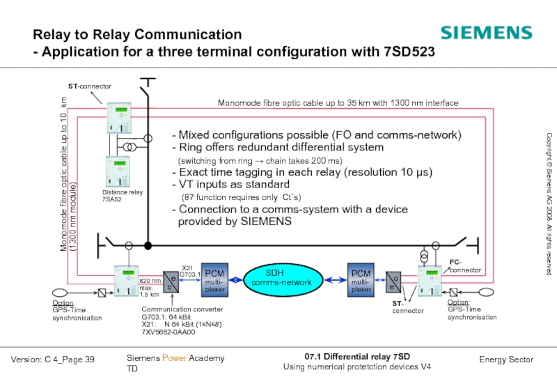
- 39. Relay to Relay Communication - Application for a three terminal configuration with 7SD523
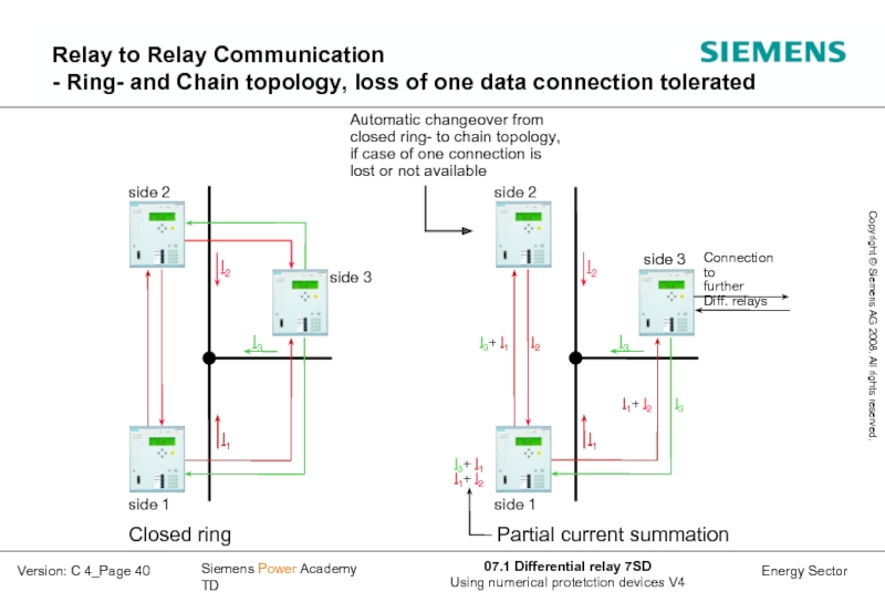
- 40. Relay to Relay Communication - Ring-
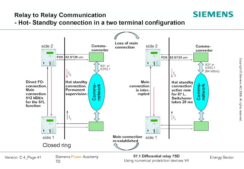
- 41. FO5 62.5/125 um side 2 I2
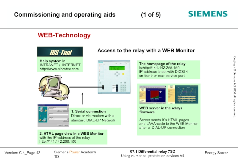
- 42. Commissioning and operating aids (1 of 5)
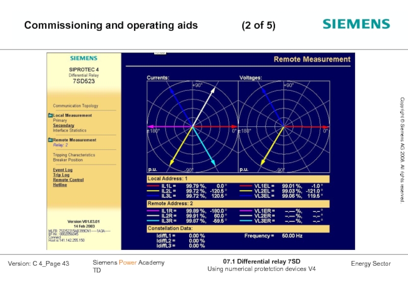
- 43. Commissioning and operating aids (2 of 5)
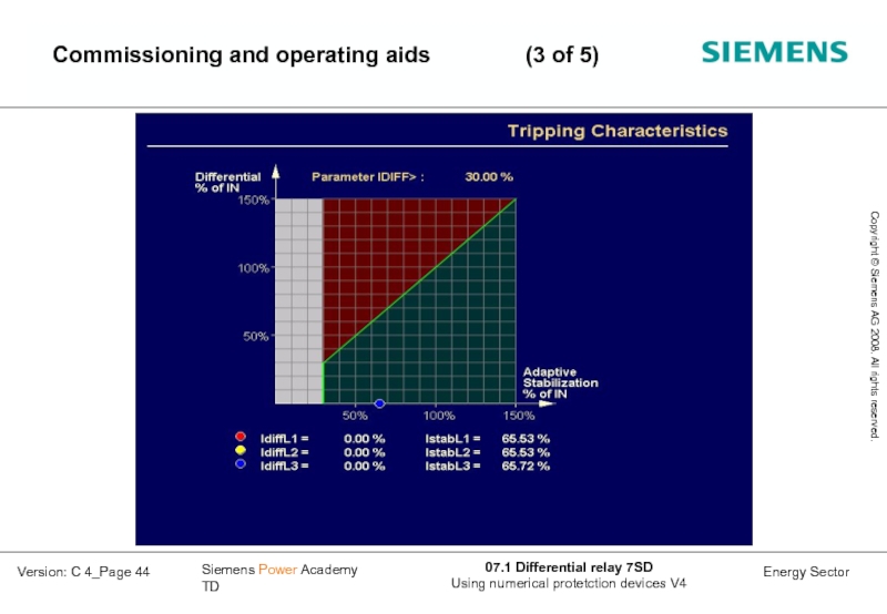
- 44. Commissioning and operating aids (3 of 5)
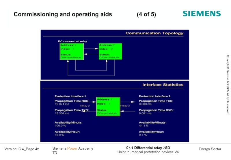
- 45. Commissioning and operating aids (4 of 5)
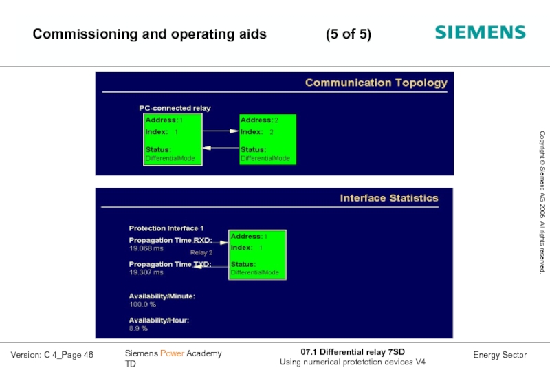
- 46. Commissioning and operating aids (5 of 5)
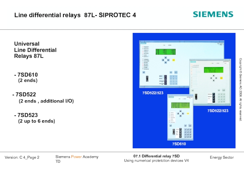
Слайд 2Line differential relays 87L- SIPROTEC 4
Universal
Line Differential
Relays 87L
- 7SD610
(2
7SD522 (2 ends , additional I/O)
- 7SD523 (2 up to 6 ends)
Слайд 3Customer Benefits
The protection adapts its characteristic by itself. Adaptive measurement
Multi terminal applications up to 6 line ends and redundant Relay to Relay communication.
A transformer inside the feeder zone of protection is fully accommodated by the feeder differential protection and configured with a few simple settings.
Current transformer mismatch 1:8 without matching transformers. Different CT classes possible.
Flexible protection data communication uses a variety of communication media.
Secure operation at unsymmetrical propagation times in Communication networks.
High speed measurement supervision
Simplified commissioning by application of WEB- technology
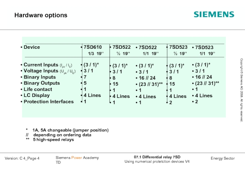
Слайд 4Hardware options
7SD610
1/3 19’’
(3 / 1)*
3
7
5
1
4 Lines
1
7SD522
½ 19’’
(3 / 1)*
3 / 1
8
15
1
4 Lines
1
7SD523
½ 19’’
(3 / 1)*
3 / 1
8
15
1
4 Lines
2
Device
Current Inputs (Iph / IE)
Voltage Inputs (Uph / UE)
Binary Inputs
Binary Outputs
Life contact
LC Display
Protection Interfaces
* 1A, 5A changeable (jumper position)
// depending on ordering data
** 5 high-speed relays
7SD522
1/1 19’’
(3 / 1)*
3 / 1
16 // 24
(23 // 31)**
1
4 Lines
1
7SD523
1/1 19’’
(3 / 1)*
3 / 1
16 // 24
(23 // 31)**
1
4 Lines
2
Слайд 10IDiff>: Vector comparison with Advanced Fourier filters
Complex vector
I = 2/N ( IC + jIS)
Optimized filtering coefficients for
7SD52 / 7SD610 designed for suppressing
decaying DC-components 4 times better
then conventional Fourier-filters.
Overcome stability problems with
decaying DC-components
Sine component:
Cosine component:
iN
samples from
AD-converter
n
n
7SD52./610: N=20 samples / cycle
weight
factors
Слайд 12Example: CT class 10P10, Sn = 10VA , Isn= 1A
10% tolerance
Thumb rule:
Rct ≈ 0.1...0.2 · Rb
Nominal burden :
If less then rated burden is connected to the CT,
the CT- error for load conditions (εLoad) can be used for calculations with
currents higher than the nominal current of the CT (Ipn) !
(In the example here: εLoad could be taken for currents up to 4·Ipn
with: KSSC: rated symmetrical short-circuit
current factor (IEC 60044-6)
KALF_N: rated Accuracy Limit Factor
KALF: actual Accuracy Limit Factor
Rct: secondary winding resistance
Rb: rated resistive burden
R’b: actual resistive burden (RLEADS + RRelay)
IDiff>: Settings for the “CT – parameters” (1 of 2)
Слайд 16IDiff>: Adaptive differential relaying Restraint current with
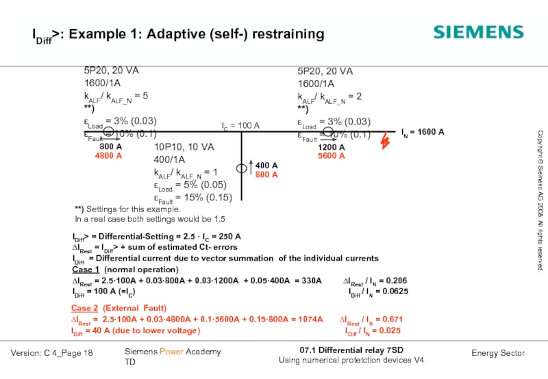
Слайд 18
5P20, 20 VA
1600/1A
kALF/ kALF_N = 5 **)
εLoad = 3% (0.03)
εFault =
IDiff> = Differential-Setting = 2.5 · IC = 250 A
∆IRest = IDiff> + sum of estimated Ct- errors
IDiff = Differential current due to vector summation of the individual currents
Case 1 (normal operation)
∆IRest = 2.5·100A + 0.03·800A + 0.03·1200A + 0.05·400A = 330A ∆IRest / IN = 0.206
IDiff = 100 A (=IC) IDiff / IN = 0.0625
IC = 100 A
800 A
4800 A
400 A
800 A
1200 A
5600 A
IN = 1600 A
Case 2 (External Fault)
∆IRest = 2.5·100A + 0.03·4800A + 0.1·5600A + 0.15·800A = 1074A ∆IRest / IN = 0.671
IDiff = 40 A (due to lower voltage ) IDiff / IN = 0.025
5P20, 20 VA
1600/1A
kALF/ kALF_N = 2 **)
εLoad = 3% (0.03)
εFault = 10% (0.1)
10P10, 10 VA
400/1A
kALF/ kALF_N = 1
εLoad = 5% (0.05)
εFault = 15% (0.15)
**) Settings for this example.
In a real case both settings would be 1.5
IDiff>: Example 1: Adaptive (self-) restraining
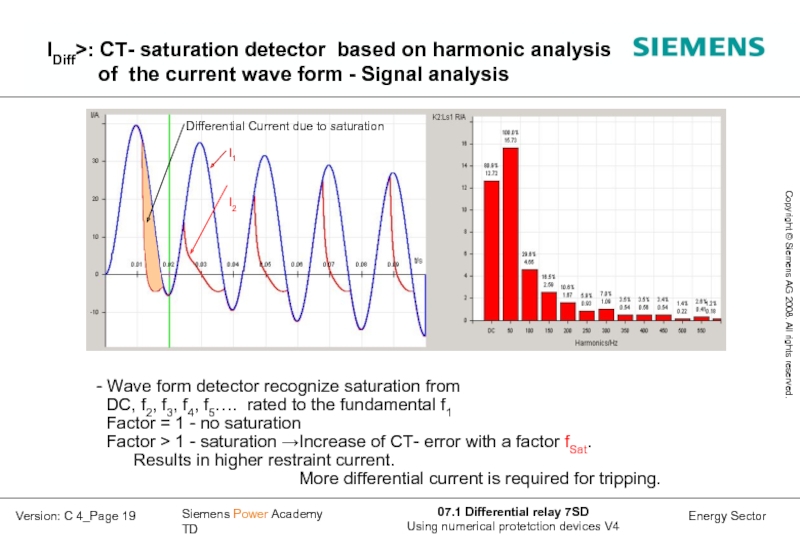
Слайд 19IDiff>: CT- saturation detector based on harmonic analysis
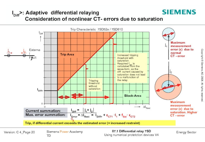
Слайд 20Trip, if differential current exceeds the estimated error (= increased restraint)
IDiff
IError = ∆IRest = IDiff> + εCT1 ·I1 + fSat· εCT2 ·I2
Current summation:
Max. error summation:
IDiff>: Adaptive differential relaying
Consideration of nonlinear CT- errors due to saturation
Слайд 22IDiff>: Adaptive consideration of a permanent time
(For more details:
refer to 7SD52 Synchronisation)
Слайд 23IDiff>: Adaptive consideration of a permanent
Diff. current:: IDiff = IC + ∆Isync
Rest. current: ∆IRest = IDiff> + CT-errors + ∆Isync
Total “Restraint Current”:
∆IRest = IDiff> + fSat1· εCT1 ·I1 + fSat2· εCT2 ·I2 + ∆Isync
Слайд 26IDiff>> (QDiff) : Fast current comparison algorithm
Q2
Corrected time instants
after end-to-end time synchronisation
Calculated restraint values from CT-errors
(always higher CT-error is taken).
Similar principal as vector comparison for restraint current calculation.
Setting IDiff>>: > ILoad,max
Q1
Слайд 28Application - Transformer and line/cable
in the protection zone
20 MVA, 110
10P10, 10 VA, 200/1A
10P10, 10 VA, 500/5A
Settings of the transformer winding data's in each relay
with vector group matching, ratio adaptation and zero sequence elimination
Differential set point is rated to the nominal current of the transformer
Inrush restraint with second harmonic included (time limit for Cross block)
High set element for immediate trip (12 ms) through heavy internal fault currents
trip
command
2 km
87T
50/51
50 BF
49
∆
Слайд 30Relay to Relay Communication Designed for the use of Digital Communication Networks
Main features of the relay to relay communication
Слайд 32Relay to Relay Communication
- Communication modules, Protection Interface (PI)
Options for the
Plug in
modules
Слайд 34Relay to Relay Communication
- Application: Fibre optic connection
Direct connection with
Слайд 35Relay to Relay Communication
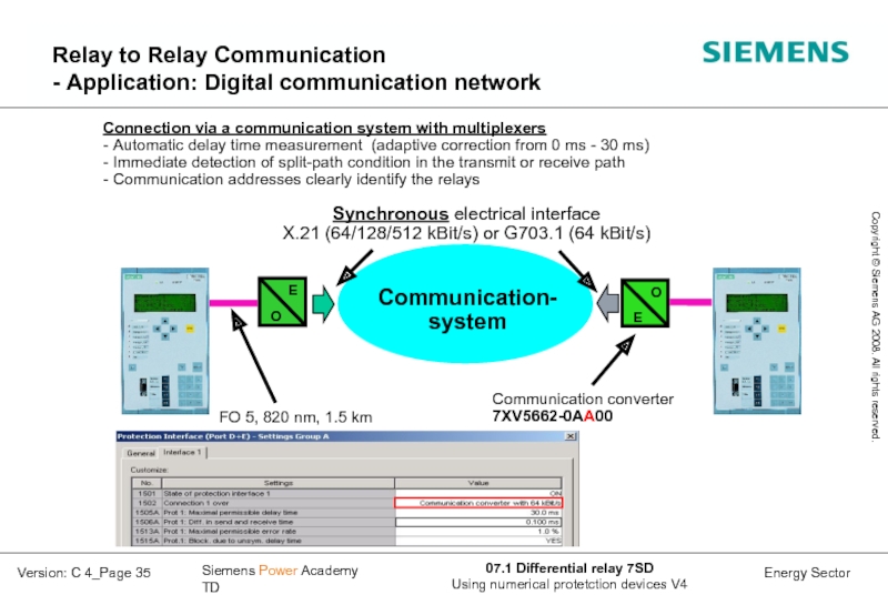
- Application: Digital communication network
E
O
Communication-
system
Communication converter
7XV5662-0AA00
FO 5,
Synchronous electrical interface
X.21 (64/128/512 kBit/s) or G703.1 (64 kBit/s)
Connection via a communication system with multiplexers
- Automatic delay time measurement (adaptive correction from 0 ms - 30 ms)
- Immediate detection of split-path condition in the transmit or receive path
- Communication addresses clearly identify the relays
Слайд 40Relay to Relay Communication - Ring- and Chain topology, loss of
Слайд 41FO5 62.5/125 um
side 2
I2
I1
Direct FO-
connection.
Main
connection
512 kBit/s
for the 87L
function
Closed ring
side
Comms-
converter
Comms-
network
X21 or
G703.1
Hot standby
connection.
Permanent
supervision.
I2
I1
side 1
Comms-
converter
Comms-
network
FO5 62.5/125 um
X21 or
G703.1
(64 kBit/s)
Hot standby
connection
active now
for 87 L.
Switchover
takes 20 ms
Main
connection
is inter-
rupted
Loss of main
connection
Main connection
re-established
side 2
Relay to Relay Communication
- Hot- Standby connection in a two terminal configuration

